A Hybrid Image Compression Technique using
Symmetric Wavelet for Multi-Application Smart Card
Application
L. M. Palanivelu
Velalar College of Engineering & Technology Thindal, Erode
India-638012
P. Vijayakumar,
Ph.D Professor-Department of EEE Karpagam College of EngineeringCoimbatore - 641 0322
ABSTRACT
This paper proposes an improved wavelet with approximating function which is symmetric in nature is proposed for compression technique. Multi-application smart cards are fast replacing the conventional cards such as driving license, health insurance card, identity card, credit card with a single card. Thus, the amount of data stored in the smart card is high, requiring methods to compress the data for effective usage of the cards. Segmentation of Region of Interest (ROI) is explored to achieve higher compression rate. The images are segmented by an extension of active contour segmentation model based on Particle Swarm Optimization (PSO) to optimize the segmentation as proposed in our previous work. The ROI and Non-ROI obtained is compressed using lossless and lossy compression respectively, using the proposed wavelet technique.
General Terms
Wavelet CompressionKeywords
Multi-Application Smart cards, Image Segmentation, Image Compression, Active contour model, Particle Swarm Optimization, Biorthogonal Wavelets.
1.
INTRODUCTION
Multi-Application Smart card is the future of the smart cards which integrates credit cards, healthcare cards, and public transport cards and so on, into a single card [1]. Smart cards have embedded integrated circuits containing memory and microprocessor components. As the smart cards carry highly sensitive information, incorporating security, authentication measures for the protection of the card holder is a must. The major challenge faced by the smart card is its limited memory size. Thus, data of various images including fingerprint, personal identity photo and medical images are stored in a compressed format for efficient usage of memory space. Compression techniques decrease image file size by reducing data needed to represent an image with similarity to the original through redundant information removal. Mathematically, compression means encoding a pixel array into statistically uncorrelated dataset. This is to ensure storage and transmission, and being decoded to reconstruct the original image through lossless approach or an image approximation through a lossy approach. Image compression systems comprise of an encoder and decoder. The Encoder uses algorithms that exploit redundancies to represent compressed image data while decoders reconstruct an original image from compressed data.
Compression algorithms are either lossless or lossy techniques. In the former, images are fully encoded and are
reconstructed without change in pixel intensity but the compression ratio is low. In lossy compression, encoding has acceptable deterioration in the reconstructed image, with high compression ratio. Lossless compression methods are used in applications including satellite image procession, medical image compression where data loss could lead to incorrect predictions or diagnosis. Lossy compression methods are used in compressing general purpose photographs where minor data loss does not matter much. Image encoding is done through transforms which convert data from a spatial to a frequency domain. Transformed domain removes redundancies through pixel mapping prior to encoding leading to few transform coefficients. Only significant coefficients are encoded for compression, while many insignificant coefficients are removed without reconstructed image quality being affected. However, ideal transform mapping should be totally reversible.
In the smart card, images related to the card holder medical history, face, fingerprint, palmprint are stored. As fingerprint, palm print is required for authentication purposes; loss in data during reconstruction is not acceptable. Similarly, medical images impact diagnosis and loss of information in diagnostically critical regions is not feasible. Thus, Region of Interest (ROI) based image segmentation and compressions provide the best alternative where lossy image compression is not feasible. Region of Interest (ROI) refers to the crucial part of the image which is of use for a particular purpose like the boundaries of the diseased area. Lossless compression can be performed in ROI, and lossy compression can be applied to the Non-ROI. Thus, improving the overall compression rate achieved for images without any loss of data in the ROI. In this paper, it is proposed to use ROI based segmentation technique on various images stored in a multi-application smart card. Multi Image Particle Swarm Optimization (MI-PSO) [2] with the active contour is used to find the image contour. The proposed modified biorthogonal wavelet is used for image compression.
2. PREVIOUS RESEARCH
JPEG2000 alone, respectively. Coding gains of 77.5% and 86.5% are likewise obtained for an MRI image sequence. To solve problems in global optimization, Particle swarm optimization (PSO), is a very efficient tool. Up to now a single learning pattern is implemented to all particles including the particles in a swarm that implements the same method which is generally observed in PSO algorithms. A specific particle may lack intelligence that makes it not capable to manage various complicated situations is because of this monotonic learning pattern. For global optimization problems, Changhe Li et al., [4] proposed a new algorithm called self-learning particle swarm optimizer (SLPSO), to tackle various complicated situations in the search space; each particle in the SLPSO consists of a set of four strategies. At the individual level by employing an adaptive learning framework the cooperation of the four strategies is achieved that allows the selection of optimal strategy of a particle considering its own local fitness landscape. On a set of 45 test functions and two real-world problems, the experimentation of SLPSO illustrated that the proposed method revealed excellent performance than the other equivalent algorithms. The best performance of SLPSO makes it suitable to be implemented in different problems.
Sehoon Yea et al., [5] proposed a two-stage near-lossless compression method. To ensure a given error bound in the pixel domain, it is present to the “lossy plus residual coding” class and contains lossy layer that is wavelet-based pursued by arithmetic coding of the quantized residual. In order to attain the least total bit rate, the emphasis is on the choosing of the optimum bit rate for the lossy layer. In the proposed technique, using a wavelet-based lossy layer, to locate the optimum bit rate, it does not necessitate iteration of decoding and inverse discrete wavelet transform in succession, unlike other equivalent lossy plus lossless methods. To evaluate the optimal bit rate, a simple method based on the critical rate argument from the independence of the residual error and the rate-distortion theory is used. Comparing the proposed methods results with other state-of-the-art near-lossless coders proposed in the literature the performance in terms of bit rates in near-lossless and lossless coding was comparable.
For active contours, gradient vector flow (GVF) is an efficient external force. The isotropic nature of GVF handicaps its performance. An anisotropic NGVF model is proposed recently that maintains the diffusion in the normal direction of the isophotes, but it tends to remove the weak boundaries and is also sensitive to noise. For snake models, Yuanquan Wang et al., [6] proposed the normally biased GVF (NBGVF) external force that maintains the diffusion in the tangential direction of the isophotes and in the normal direction are the biases. In the boundaries, the biasing weight proceeds to zero, and in homogeneous regions it approaches 1. As a result, the weak edges are preserved, and the noise is smooth out in the NBGVF snake. Simultaneously the other desirable properties of GVF and NGVF snakes like enlarged convergence to u-shape concavity, capture range, and insensitivity to initialization are retained. Evaluation is performed on the
synthetic and real images using these properties. The results revealed from NBGVF snake is that it outperforms and is a superior substituent to GVF and NGVF snakes.
In order to view DICOM compliant medical images implementing wavelet compression with ROI coding support, on mobile devices Doukas et al., [7] proposed a Picture Archiving and Communication Systems (PACS) application. Additionally, the initial results obtained from its pilot application are presented and over a heterogeneous radio network segments such as DVB-H, GPRS and IEEE 802.11b its performance is illustrated. Hence the proposed method supports physician’s to perform diagnosis in the regions of specific interest with high quality factors upon user’s request.
3. METHODOLOGY
The present work focuses on three major areas namely the active contour model for image segmentation, Particle swarm optimization for obtaining optimized ROI and an novel mother wavelet for lossless and lossy compression.
3.1 Active Contours
Active contour, or snake model, is an influential variational model for image segmentation from its 1988 debut [8]. Usually, active contours could be categorized into region-based models [9], [10] and edge-region-based models [8], [11], [12] on the basis of how image data is employed. Region-based methods employ global region information for deforming a contour while edge based methods depend on image gradient to stop contour evolution. The idea behind snake model involves lowering energy functional that integrates a curve’s geometric properties and image features. Using variations calculus, the minimization problem is transformed to solve PDEs and derivatives from geometrical properties are known as internal force and those from image features the external force.
The basic Active model is given by
2 0
( )
(
,
, )
.
( )
( , )
inside C
F c c C
Length C
u x y
c
dxdy
where c+ and c- are constant
unknowns representing the average value of u0 inside and
outside the curve, respectively. The parameters
0
and,
0
are weights for the regularizing term and the fitting term, respectively. The above model can be rewritten as
20 0
(
,
, )
.
{
0}
,
F c c
Length
u
x y
c
dxdy
for the level set formation where
,
:
,
0
c
x y
x y
2 0
( )
( , )
outside C
u x y
c
dxdy
2 00
u x y
,
c dxdy
3.2Multi
Image
Particle
Swarm
Optimization (MI-PSO)
In the last decade, particle swarm optimization (PSO) was studied and applied for academic and real world problems with good results [13]. But, many experiments revealed that this basic PSO algorithm falls into a local optima easily when solving complex multimodal problems [14] with large numbers of local optima. In PSO literature for most algorithms till now, all swarm particles use only a single learning pattern. This may lead to an intelligence lack for a particle to handle different complex situations. An example is that different problems might consist of differing properties due to various fitness landscape shapes. To ensure effective solution to these issues, particles may need different learning strategies to handle varying situations. This may be true even for a specific problem as local fitness landscape shape in different sub regions of a specific problem might be different, like composition benchmarks in [15].
A major issue faced in multi-application smart card application is the varied images stored in the smart card. Many a time the convergence achieved by PSO is premature resulting in a non-idealistic segmentation. Multi Image PSO (MI-PSO) [2] proposed in our previous study which extends the classical PSO to optimized convergence even if the image domain is different.
Multi Image Particle Swarm Optimization (MI-PSO) uses a swarm of particles
P
i for each control pointcp
i for findingthe best movement for the active contour. At each iteration based on the globally best position ‘gbest’ of swarms
1 1
i i
cp andcp
, the gbest of
P
iiscp
i. The iterations arecontinued to compute the ‘gbest’ until the active contour becomes stable. A 5X5 window size is used instead of standard 3X3 window to increase the speed of optimization. The steps in the proposed algorithm are
a)
Assign the best particle position ‘pbest’ and global position ‘gbest’ for each control pointcp
i.
b) For each
cp
iallocate the search window of 5x5 andpush the particles to the outer boundaries.
c) For each particle
p
ioptimize by minimizing thelocal energy.
d)
‘
gbest’ now becomes the new control pointe) Repeat steps b to d for all
cp
f) Check whether the active contour energy is stable with the current iteration or go to step b for the next iteration.
3.3 EZW encoder for proposed wavelet
A needed characteristic in an image compression scheme is an embedded bit stream. When encoded as embedded bit stream, an image is ready for transmission, where the total image is seen and becomes clearer as it is received. This is in sharpcontrast to raster-based transmission where an image is transmitted row-by-row, totally decompressed, but with only a part of the image being visible till it is completely received. The Embedded Zero trees of Wavelets (EZW) algorithm produce an embedded bit stream from the image that was transformed into a frequency domain using the DWT. The EZW algorithm generated by bit stream represents a series of binary decisions which distinguishes an image from null or all gray image. With this, an encoder can terminate encoding at any time, allowing a target bit rate to be achieved accurately; similarly, a decoder can stop decoding at any time to allow progressive transmission.
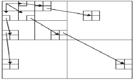
[image:3.595.319.537.435.565.2]Four key concepts that describe the EZW algorithm are Discrete wavelet transforms, exploiting self-similarity in image to predict the absence of essential information, Entropy-coded successive-approximation quantization and adaptive arithmetic coding for lossless data compression. Embedded Zerotrees of wavelet algorithms process hierarchical wavelet decomposition of an image [16]. EZW exploits self-similarity in images through the introduction of a data structure called a zero tree. The idea is that if a coefficient in a coarse scale is insignificant with regard to a given threshold, then all wavelet coefficients of the same orientation in the same spatial location at finer scales are also likely to be insignificant. Figure 1 shows a zero tree structure where each coefficient has four descendants at a finer scale, with the exception of the coarsest scale, the LL sub band, where every coefficient has three descendants alone.
Figure 1: Zerotree structure of EZW algorithm To perform the embedded coding, an initial threshold is chosen
⌊ | )|))⌋
where h(x, y) denotes a coefficient.
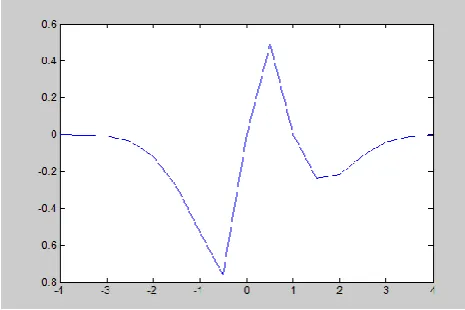
Figure 2: Proposed Mother Wavelet
The encoder alternates between passes: the dominant pass and the subordinate pass, for total encoding of the image or desired bit rate is achieved. Two separate lists are also maintained: a dominant list, containing coefficient coordinates which has not been found significant with regard to the current threshold T, and a subordinate list that contains magnitudes of coefficients found to be significant with respect to the current threshold T. Let T = t0. During a dominant pass, coefficients with coordinates on dominant list are compared to T to determine the significance. A coding alphabet of four symbols isused during dominant pass: POS (positive significant), NEG (negative significant), ZTR (zerotree root), and IZ (isolated zero). If the absolute value of a coefficient is greater than or equal to T, the coefficient is significant and a POS or NEG is encoded, corresponding to the coefficient sign. The coefficient’s magnitude is added to the subordinate list, and the raster coefficient is set to zero to ensure it does not prevent the occurrence of a zerotree on future dominant passes at smaller thresholds. If the absolute value of a coefficient is less than T, and if all coefficients at spatial locations in finer scales (corresponding to zerotree structure in Figure 1) are insignificant, then a ZTR (zerotree root) is encoded. If a child of a potential zerotree is significant, then an IZ (isolated zero) is encoded.
A subordinate pass follows a dominant pass where the next most significant bit of coefficients in the subordinate list is outputted. In other words, first T is subtracted from the coefficient. Then T/2 is used as the subordinate threshold. If the coefficient is greater than or equal to T/2, then a ’1’ is outputted, otherwise a ’0’ are outputted.
After the subordinate pass, threshold is halved (T = T/2), and another dominant pass started. This continues till threshold T = 0, or the encoder halts the process because target bitrate was reached. For color images, the image is converted to the YUV color scheme. An initial threshold is the largest value in the Y band. A dominant pass is performed on each separate band in the image, the Y, U, and V bands. Then the subordinate pass is performed on all values in the subordinate list.
Figure 3 shows the block diagram of the EZW Encoding and decoding process for image compression.
Fig 3: Block diagram for Wavelet-EZW Encoder for Image Compression
4. RESULTS
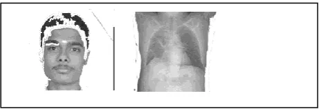
[image:4.595.314.575.106.218.2]The proposed mother wavelet tested on different types of images commonly used in multi-application smart cards. The test images include MRI medical images of the heart portion, fingerprint image and passport image used for identification as shown in Figure 4.
Figure 4: Original images to be stored in the smart card. It is seen from Figure 4 that each and every image has to retain its originality and hence maintaining the features in the Region of Interest (ROI) is crucial.
Figure 5 illustrates the ROI extracted through Active Contour Model (ACM).
Figure 5: Segmentation using Active Contour Model
From figure 5 it is seen that for the face photo, the ACM does not converge effectively. Increasing the iterations may help in convergence but this also increases the processing time. Figure 6 shows the segmentation using the Multi Image Particle Swarm Optimization (MI-PSO)
The ROI selected is shown in Figure 7.
.
Figure 6: Segmentation using the MI-PSO Wavelet
Transform
Image
Threshold EZW Encoder
Quantizer
Dequantizer EZW
Decoder Inverse Wavelet
Transform
[image:4.595.295.586.338.403.2] [image:4.595.296.582.510.579.2] [image:4.595.298.547.655.731.2]. Figure 7: The Region of Interest extracted for compression
Using the outer contour edge as the mask, the image can be segmented into ROI and Non ROI.
[image:5.595.64.295.69.148.2]. The original images and the ROI images are compressed by lossless compression using the proposed wavelet. The compression ratios obtained is tabulated in Table 1. The proposed technique is compared with [17]
Table 1: Compression ratio of original and segmented images with comparison
Original image-Proposed
Original Image - Palanivelu et al., 2012
Segmented ROI
Segmented ROI-Palanivelu et al., 2012
Segmented Non ROI
Segmented Non ROI-Palanivelu et al., 2012
Type of
Compression Lossless Lossless Lossless Lossless Lossy Lossy
Face 49.18% 51.13% 48.27% 51.13% 99.25% 99.25%
Chest 49.14% 51.14% 72.47% 75.00% 99.30% 99.30%
Finger 57.32% 60.78% 71.13% 74.07% 99.68% 99.68%
The compression ratios obtained is tabulated in Table 1.
From the above table it is seen that the overall compression of the images after image fusion will be in the tune of 75-85%. This is a definite improvement over lossless compression techniques. Compared to [17] the proposed technique improves the compression ratio by 4.8% without segmentation and by 4.33% after segmentation.
5. SUMMARY AND CONCLUDING
REMARKS
The major issues faced in multi-application smart card application are the varied images stored and limited memory. For the memory constraint faced, the images stored in the smart card memory are compressed. In this paper, a novel biorthogonal wavelets with approximating function and symmetric in nature is proposed for compression technique. Segmentation of Region of Interest (ROI) using active contours is explored to achieve higher compression rate. The images are segmented by an extension of active contour segmentation model based on Particle Swarm Optimization (PSO) to optimize the segmentation as proposed in our previous work. The ROI and Non-ROI obtained is compressed using lossless and lossy compression respectively, using the proposed wavelet technique. Results obtained showed that compressing the ROI area without losses and compressing the non ROI using lossy compression using proposed wavelet achieves higher compression ratio.Improvement of compression ratio over 4% has been obtained consistently for different images.
6. REFERENCES
[1] Mike Hendry “Multi application smart cards: Technologies and applications”, Cambridge university press, 2007.
[2] Palanivelu, L. M. And Vijayakumar, P., “Effective Image Segmentation Using Particle Swarm Optimization for Image Compression in Multi Application Smart Cards”, World Congress on Information and Communication Technologies (WICT), 2011, pp: 535-539.
[3] Shaou-Gang Miaou, Fu-Sheng Ke, and Shu-Ching Chen, “A Lossless Compression Method for Medical Image Sequences Using JPEG-LS and Interframe Coding”, IEEE TRANSACTIONS ON INFORMATION TECHNOLOGY IN BIOMEDICINE, VOL. 13, NO. 5, SEPTEMBER 2009, pp:818-821.
[4] Changhe Li, Shengxiang Yang, and Trung Thanh Nguyen, “A Self-Learning Particle Swarm Optimizer for Global Optimization Problems”, IEEE Transactions On Systems, Man, And Cybernetics—Part B: Cybernetics, Vol. 42, NO. 3, JUNE 2012, pp:627-646.
[5] Sehoon Yea, and William A. Pearlman, “A Wavelet-Based Two-Stage Near-Lossless Coder”, IEEE Transactions On Image Processing, Vol. 15, NO. 11, NOVEMBER 2006, pp: 3488-3500.
[6] Yuanquan Wang, Lixiong Liu, Hua Zhang, Zuoliang Cao, and Shaopei Lu, “Image Segmentation Using Active Contours With Normally Biased GVF External Force”,IEEE Signal Processing Letters, Vol. 17, No. 10, October 2010, pp: 875-878
Annual Conference Shanghai, China, September 1-4, 2005, pp: 3779-3784.
[8] M. Kass, A. Witkin, and D. Terzopoulos, “Snakes: Active contour models,” Int. J. Comput. Vis., vol. 1, no. 4, pp. 321–331, 1988.
[9] X. Du and T. D. Bui, “A new model for image segmentation,” IEEE Signal Process. Lett., vol. 15, pp. 182–185, 2008.
[10]S. Mahmoodi, “Shape-based active contours for fast video segmentation,” IEEE Signal Process. Lett., vol. 16, pp. 857–860, 2009.
[11]V. Caselles, R. Kimmel, and G. Sapiro, “Geodesic active contours,” Int. J. Comput. Vis., vol. 22, no. 1, pp. 61–79, 1997.
[12]J. Melonakos, E. Pichon, S. Angenent, and A. Tannenbaum, “Finsler active contours,” IEEE Trans. Pattern Anal. Mach. Intell., vol. 30, no. 3, pp. 412–423, 2008.
[13]R. Poli, J. Kennedy, and T. Blackwell, “Particle swarm optimization: An overview,” Swarm Intell., vol. 1, no. 1, pp. 33–58, 2007.
[14]J. J. Liang, A. K. Qin, P. N. Suganthan, and S. Baska, “Comprehensive learning particle swarm optimizer for global optimization of multimodal functions,” IEEE Trans. Evol. Comput., vol. 10, no. 3, pp. 281–295, Jun. 2006.
[15]P. N. Suganthan, N. Hansen, J. J. Liang, Y.-P. C. K. Deb, A. Auger, and S. Tiwari, “Problem definitions and evaluation criteria for the CEC 2005 special session on real-parameter optimization,” Nanyang Technological Univ., Singapore, Tech. Rep., 2005.
[16]J. Shapiro, “Embedded image coding using zerotrees of wavelet coefficients”IEEE Trans. on Signal Processing, 1993, No. 12, pp:3442-3462.