A Proposed Block-Coding Technique of an Image
based on Fractal Compression
Shimal Das
Dibyendu Ghoshal,
PhD Assistant professor Associate professor Tripura Institute of Technology, National Institute of TechnologyNarsingarh, Tripura, India, Agartala, India
ABSTRACT
Now a day the fractal image compression technique models a natural image using a contractive mapping called fractal mapping in the image space. Due to reducing the search complexity of matching between range block and domain block in fractal image compression is one of the most active research areas lately. There are two main characteristics of this approach are (a) It relies on the assumption that image redundancy can be efficiently captured and exploited through piecewise serf-transformability on a block-wise basis, and (b) It approximates an original image by a fractal image, obtained from a finite number of iterations of an image transformation called a fractal code. This paper proposed to this approach as Fractal Block Coding. For such an application, the general problem statement is the following. For any given original discrete image specified by an array of pixels, how can a computer construct a fractal image, the coded image-which is both visually close to the original one, and has a digital representation which requires fewer bits than the original image? The proposed coding scheme carried out an approach to image coding based on a fractal theory contractive transformations defined piecewise. In experimental results show that compared with Jacquin coding scheme and our proposed coding scheme achieves an average of 89% reduction in encoding time and improves the efficiency of search. Simultaneously the compression ratio and quality of decoded images are guaranteed to the same as Jacquin coding scheme for the same images.
General Terms
Digital image processing, Pattern Recognition
Keywords
Fractals Coding, Image Encoding, IFS, LIFS, Fractal Compression
1. INTRODUCTION
The concept of fractal was introduced by Mandelbrot [1] as an alternative to the traditional Euclidean geometry mainly for dealing with shapes generated by nature. Currently, the interest of applying this theory has been steadily growing. Now a day in computer graphics and image processing has been to use iterated function system (IFS) to generate and describe both man-made fractal- like structures and natural images. Barnsley et al. were the first to present the concept of fractal image compression using IFS [1]. Deterministic Fractals have the intrinsic property of having extremely high visual complexity while being very low in information content, as they can be described and generated by simple
2. THEORETICAL FOUNDATIONS
2.1 Self-affine and self-similar
transformation
Fractal image compression algorithm is based on the fractal theory of self-similar and self-affine transformations [25]. Definition 1. A self-affine transformation w: Rn → Rnis a transformation of the form w(x) = T(x) +b, where T is a linear transformation on Rn and b ϵ Rn is a vector.
Definition 2. A mapping w : D→ D; D Rn is called a contraction on D if there is a real number c ϵ (0,1), such that d(w(x), w(y))≤ cd(x, y) for x, y ϵ Dand for a metric d on Rn. The real number c is called the contractility of w. Definition 3. If d(w(x), w(y)) = cd(x, y), then w is called a similarity. A family { w1, …., wm } of contractions is known as a local iterated function system (LIFS). If there is a
subset such that for a LIFS { w1, …., wm }, m
F=
U
w i (F) (1) i=1then F is said to be invariant for that LIFS. If F is invariant under a collection of similarities, F is known as a self-similar set.
Let S denote the class of all non-empty compact subsets of D. The δ-parallel body of A ϵ S is the set of points within distance δ of A, i.e.
A = { x ϵ D: there exists α ϵ A such that ׀x-a׀ ≤ δ }. . (2)
Let us define the distance d(A,B) between two sets A, B to be d (A,B) = inf { δ: A B and B A } (3)
The distance function is known as the Hausdorff metric on S (other distance functions can also be used).
Given a LIFS { w1, ………. , wm }, there exists an unique compact invariant set F, such that
m
F=
U
w i (F) (4) i=1This F is known as the attractor of the system. If E is a compact non-empty subset such that wi(E) and
Wi (E) E and m
W(E) =
U
w i (F) (5) i=1The proposed method define the k-th iteration of w, wk (E), to be
w0 (E) = E, wk (E) = w (wk-1(E)) .. . (6) ∞
For k 1, then got F =
∩
wk (E) (7) i=1The sequence of iteration wk (E) converges to the attractor of the system for any set E. This means that it may carry out a family of contractions that approximate complex images and, using the family of contractions, the images can be stored and transmitted in a very efficient way. Another present method is a LIFS; it is straightforward to obtain the encoded image. If any one wants to encode an arbitrary image in this way, they will have to find a family of contractions so that its attractor is an approximation to the given image. Barnsley‟s Collage Theorem states how well the attractor of a LIFS can approximate of any given images.
2.2 Collage theorem
Let { w1, .., wm } be contractions on Rn so that for any x,y ϵ Rn and any i,
׀
wi(x) - wi (y)׀
≤ c ………(8)Where c ϵ (0, 1) is a constant. Let E
Rn be any non-empty compact set. Thenm
d ( E,F ) ≤ 1/(1-c) d(E,
U
wi(E)) (9)i=1
where F is the invariant set for the wi, and d is the Hausdorff metric [9].
As a consequence of this theorem, any subset of Rn can be approximated within an arbitrarily tolerance by a self-similar set, i.e., given δ ˃ 0, there exist contracting similarities { w1, …….., wm } with invariant set F satisfying d(E,F) ˂ δ . Therefore, the problem of finding a LIFS { w1, …….., wm } whose attractor F is arbitrary close to a given image I is equivalent to minimize the distance
m
d ( I,
U w
i(I)) i=12.3. Contractive transformations
A transformation w is said to be contractive if for any two points P1, P2, the distance
d(w(P1),w(P2) ) < sd(P1,P2) (10) for some s < 1, where d = distance. This formula says the application of a contractive map always brings points closer together (by some factor less than 1).
3. THE CONTRACTIVE MAPPING
FIXED POINT THEOREM
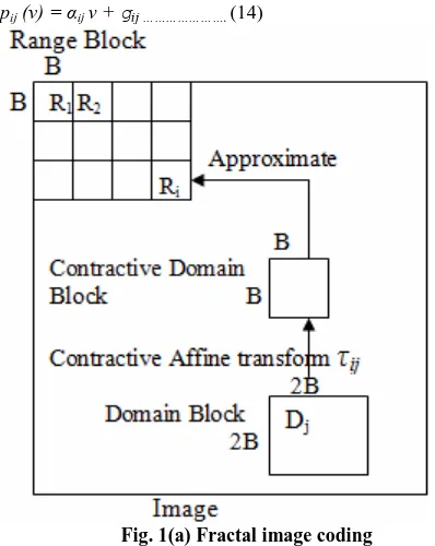
The fractal image coding makes good uses of image self-similarity in space by ablating image geometric redundant. This coding process is quite complicated but decoding process is very simple, which makes use of potentials in high compression ratio. The theory of fractal image coding is based on iterated function system, attractor theorem, and collage theorem. Regard original compressible image as attractor, how to get LIFS parameters is main problem of fractal coding [26] . For conventional fractal image coding technique, the image is partitioned into a number of non-overlapping blocks called range blocks. In spite of storing the information of the range blocks as such, only the parameters defining the affine transformations are stored. All these parameters are obtained by mapping each range block to a closely resembling block called the domain block on which the transformations are applied. Domain blocks are selected from the same image, and they can overlap. Fundamentally the size of the domain block will be twice the size of the range block. Any grayscale image can be coded by mapping the domain block D to the range block R with the contractive affine transformation, fig 1(a) shows the fractal image coding procedure, fig (b) shows the domain and Range block of “Lena” image and fig 1(c) shows the mapping of intensity value in fractal transform.
D( Ri , τik (Dk ) ) = min d( Ri , τik (Dj ) (11)
∑ (Ai,k – Āi,k )2 0≤ N≤ B
d ( Ri, τij ( Dij ) )= , (o≤ l, k ≤ B-1) B x B (12)
Where τij is an contractive affine transformation from the domain block Dj to the range block Ri; the distortion measure d( Ri , τij (Dj ) is the mean square error (MSE) between the range block Ri and the contractive domain block τij (Dj ). The contractive affine transformation τij is composed of two mappings ϕj and ϕij as follows: τij = ϕij ○ ϕj ……….(13)
The former mapping ϕj is the transformation of domain-block size to the same size as range block's. This transformation is achieved as follows: The domain block Dj is divided into non-overlapping unit blocks of size 2 × 2; And each pixel value of the transformed block ϕj ( Dj ) is an average value of four pixels in each unit block in Dj. The latter mapping ϕij consists of two steps: The first step transforms the block ϕj ( Dj ) a way of the eight transformations: rotation around center of the block ϕj ( Dj ), through 0°, +90°, +180°, and +270°, and each rotation after orthogonal reflection about mid-vertical axis of the block ϕj ( Dj ) . Those eight transformations are called isometries. The second step is the transformation ( pij ) of pixel values of a block obtained by the first step. This transformation pij is defined as
pij (v) = αij v + gij ………. (14)
Fig. 1(a) Fractal image coding
Where v is a pixel value of the block obtained by the first step, and the parameters αij and gij are computed by the least square analysis of pixel values of the range block Ri and the block obtained by the first step. These parameters αij and gij , a scaling coefficient and an offset and the IFS Parameters are as (a) Parameters to indicate a location of the best matched domain block; (b) A parameter to indicate an isometry on the best matched domain block; (c) A scaling coefficient and an offset. Proposed method quantizes these LIFS parameter.
Fig.1 (b) Domain and Range block of “Lena”
4. OVERVIEW OF ENCODING IMAGES
From the above mentioned theorem it may carried out that transformation W will have a unique fixed point in the space of all images. These transformations repeatedly apply to the images until it will converge to a fixed image.
Let any given an image f that we wish to encode.
Fig. 1 (c) Point (x, y) Di is mapped to fi (x, y)Riand the
intensity value at fi (x, y): ( fi (x, y)) is sampled in the
fractal transform
[image:3.595.334.521.72.222.2] [image:3.595.323.538.329.542.2] [image:3.595.54.253.371.621.2]Figure 2: Fractal Fern
Fig. 3. Self similar portions of Lena
5. OUR PROPOSED ALGORITHM
5.1 Encoding
From the following example suggests how the Fractal Encoding can be done. Now it may deal with a 128×128 image in which each pixel can be one of 256 levels of gray, called this picture Range Image. Then it reduce by averaging (down sampling and lowpass-filtering) the original image to
[image:4.595.318.540.229.327.2]64×64, called this new image Domain Image.Then partitioned both images into blocks 4 x 4 pixels shown in Figure 4 and performed the following affine transformation to each block as follows
(Dij) = αDij + to ……….. (15)
Where α = [ 0, 1 ], α ϵ and to ϵ [ -255, 255], to ϵ Z
So i
n this case trying to find linear transformations of Domain Block to arrive to the best approximation of a given Range Block. For each Domain Block is transformed and then compared to each Range Block Rk,l. Then the exact transformation on each domain block, i.e. the determination of α and to is found minimizingMin ∑ ( Rk,l )m,n – (Γ ( Di,j))m,n
(16) With respect to α and to
Ns 2∑
m,n ( Di,j)m,n( Rk,l)m,n – (∑m,n ( Di,j)m,n )(∑m,n (Rk,l)m,n )
α =
Ns2 ∑m,n (( Di,j)m,n)2
-
( ∑m,n ( Di,j)m,n )2 (17)(
∑m,n ( Di,j)m,n)2-
( ∑m,n ( Ri,j)m,n )2t
0=
Ns2 ∑m,n (( Di,j)m,n)2
-
( ∑m,n ( Di,j)m,n )2(18) Here m, n, Ns = 2 or 4 (blocks size). For every transformed domain block (Di,j) is compared to each range block Rk,l in order to find the closest domain block to each range block using the following distortion measure.
d
l2( Γ( Di,j), Rk,l )=
∑m,n (( Γ(Di,j)-(Rk,l )m,n )2(19) Every distortion is stored and the minimum is chosen. Then the transformed domain block which is found to be the best approximation for the current range block is assigned to that range block, i.e. the coordinates of the domain block along with its α and toare saved into the file describing the transformation. For this why is called the Fractal Code Book.
Γ( Di,j)best
Rk,l(20)
5.2 Decoding
In decoding process the reconstruction for the original image consists on the applications of the transformations describe in the fractal code book iteratively to some initial image init, until the encoded image is retrieved back. The whole image transformation can be described as follows:
n = (n-1) (21 ) Where 1 = (init), 2 = (1), 3 = (2), ….. = ...
Herecan be expressed as two distinct transformations:
[image:4.595.56.291.248.472.2]Fig. 4. Partition of Range and Domain
Again more () represents the down sampling and low pass filtering of an image W to create a domain image e.g. for reducing a 128x128 image to a 64x64 image as it may describe previously. The symbol () represents the ensemble of the transformations defined by proposed mappings from the domain blocks in the domain image to the range blocks in the range image as recorded in the fractal. So
n will converge to a good approximation of orig in less than 5 iterations
6. EXPERIMENTAL RESULT &
DISCURSIONS
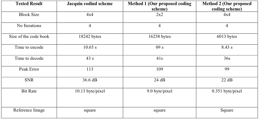
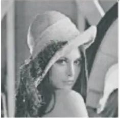
From the experiment the Lena image (128x128) are decoded the using the set-up described in Figure 5 and 6. This is performed using the 2x2 and 4x4 block size respectively and several different reference images. Table-1 shows the proposed method comparison with Jacquin method decoded images and figure-7 (a) shows the original Lena image, figure-7 (b) shows the Jacquin coding image and figure-7 (c)
[image:5.595.91.504.72.306.2]shows the our proposed method.
Table-1 shows the proposed coding scheme comparison with Jacquin coding scheme
Tested Result Jacquin codind scheme Method 1 (Our proposed coding
scheme)
Method 2 (Our proposed coding scheme)
Block Size 4x4 2x2 4x4
No Iterations 4 4 4
Size of the code book 18242 bytes 16238 bytes 6013 bytes
Time to encode 10.65 s 09 s 8.43 s
Time to decode 43 s 41s 36s
Peak Error 113 109 99
SNR 36.6 dB 24 dB 22 dB
Bit Rate 10.13 byte/pixel 9.0 byte/pixel 0.351 byte/pixel
[image:5.595.46.549.467.698.2]Fig. 5. Decoding iterations with 2x2 decoding using fractal coding
Fig.7(a) Original Lena image
Fig.7(b) Jacquin method decoded image
Fig.7(c) Our proposed method
7. CONCLUSION
In this paper described the design of digital image coding systems referred to as Fractal Block Coders which are based on a theory of iterated contractive image transformations. The proposed preliminary design issues are to select an adaptive image partition made of non-overlapping range cells. Then the encoding of an original image then consists of capturing the self-transformability of the original image by searching a global transformation pool for a transformation defined block wise-a fractal code-under which the image is approximately invariant. For a specific block-base fractal image coding system was presented as well as encoding and decoding results. Mentioned block-based fractal coding system affects all of the following: visual quality of coded images, compression, encoding complexity and speed, in a complex manner. Moreover decoding complexity remains fairly low and stable for various system designs. This strategy of piecewise self-similarity and its capture through the construction of contractive image transformations which leave
scheme for the exploitation of image redundancy for image compression-this property is what makes fractal image coding work can be applied in Medical Imaging, where doctors need to focus on image details, and in Surveillance Systems, when trying to get a clear picture of the intruder or the cause of the alarm. The proposed methods gives a clear advantage over the Discrete Cosine Transform Algorithms such as that used in JPEG or MPEG.
8. ACKNOWLEDGMENTS
We would like to thank Dr. P.K. Bose, Director, NIT, Agartala, India for supporting this research work.
9. REFERENCES
[1] B.B. Mandelbrot, The Fractal Geometry of Nature, Freeman, San Francisco, 1983.
[2] B. Mandelbrot, The Fractal Geometry of Nature. San Francisco, CA: Freeman, 1982.
[3] G. Cherbit, Fractals, Dimensions non Entireness et Applications. Paris, France: Masson, 1987.
[4] K. Falconer, The Geometry of Fractal Sets. London, UK Cambridge Univ. Press, 1985.
[5] Fractal Geometry, Mathematical Foundations and Applications. New York Wiley, 1990. Y. Fisher, E.W. Jacobs, and R. D. Boss,
[6] H-0. Peitgen and P. H. Richter, The Beauty ofFractals. Berlin: Springer, 1986.
[7] J. Gleick, Chaos, Making of a New Science. New York: Vicking, 1987.
[8] H-0. Peitgen, H. Jiirgens, and D. Saupe, Chaos and Fractals. New York Springer-Verlag, 1992.
[9] A. P. Pentland, “Fractal-based descriptions of natural scenes,” IEEE Trans. Pattern Anal. Machine Intell., vol. PAMI-6, no. 6, 1984.
[10] „Fractal surface models for communications about terrain,” SPIE Visual Comun. Image Process. 11, vol. 845, 1987.
[11] M. C. Stein, “Fractal image models and object detection,” SPIE Visual Commun. Image Process. II, vol. 845, 1987.
[12] M. F. Bamsley and S. Demko, “Iterated function systems and the global construction of fractals,” Proc. Roy. Soc. London, vol. A399, pp. 243- 275, 1985.
[13] M. F. Bamsley, V. Ervin, D. Hardin, and J. Lancaster, “Solution of an inverse problem for fractals and other sets,” Proc. Nut. Acad. Sci., vol. 83, pp. 1975-1977, 1986.
[14] M. F. Bamsley, Fractals Everywhere. New York Academic Press, 1988.
[15] M. F. Bamsley, J. H. Elton, and D. P. Hardin, “Recurrent iterated function systems,” Constructive Approximation. Berlin, Germany: Springer-Verlag, 1989, pp. 3-3 1. [16] M. F. Bamsley and A. Jacquin, “Application of recurrent
[image:7.595.108.227.72.192.2] [image:7.595.107.226.230.350.2] [image:7.595.108.226.392.508.2][17] M. F. Bamsley, A. Jacquin, F. Malassenet, and L. Reuter, “Harnessing chaos for image synthesis,” in Proc. SIGGRAPH, ‟88, 1988, pp. 131-140.
[18] A. Foumier, D. Fussell, and L. Carpenter, “Computer rendering of stochastic models,” Commun. ACM, vol. 25, pp. 371-384, 1982.
[19] J. C. Hart, D. J. Sandin, and L. H. Kauffman, “Ray tracing deterministic 3-D fractals,” Comput. Graph., vol. 23, no.3, pp. 91-100, 1989.
[20] C. Hart and F. K. Musgrave (Co-chairs), “Fractal modelling in 3D computer graphics and imaging,” in SIGGRAPH ‟91, course notes, 1991.
[21] H-0. Peitgen and D. Saupe, The Science of Fractal Images. New York Springer-Verlag, 1988
[22] L. Hodges-Reuter, “Rendering and magnification of fractals using iterated function systems,” Ph.D. dissertation, Georgia Inst. Technol., Atlanta, 1987 [23] F. J. Malassenet, “Texture coding using a pyramid
decomposition,” in Proc. ICASSP-93, 1993, vol. V, pp. 353-356.
[24] R. Rinaldo and A. Zakhor, “Fractal approximation of images,” in Proc. Data Compression Conf.. Mar.-Apr. 1993, p. 451.
[25] Shouji Chen, Liming Zhang: Fractal and image compression. Shanghai Science And Technology Education Publishing House(1998)