Performance Analysis in Dynamic VLR based Location
Management Scheme for the Omni Directional Mobility
Movement for PCS Networks
Rachana Singh Sisodia
Sarvpal Singh
M.Tech. Student Associate Professor
Department of Computer Science & Engg. Department of Computer Science & Engg. M.M.M. Engg. College, Gorakhpur M.M.M. Engg. College, Gorakhpur
ABSTRACT
Location management plays an important role in guaranteeing the effective operation of Personal Communication services (PCS). In this paper a dynamic VLR (visitor location register) based location management is introduced for PCS networks. In this, MSC gathers the details about mobile terminals (MT) and performs location registration. This scheme is analytically examined for Omni directional movement of MTs and also it reduces the location management cost.
General Terms
Location Management, PCS Networks, Visitor Location Register, Mobility Movement.
Keywords
PCS, Location Management, Call Delivery, Mobile Terminals (MTs), Location Area.
1. INTRODUCTION
In mobility management, location management is the key task that deals with the mechanisms for tracking the location of the mobile terminal (MT). . The location management performs three fundamental tasks: (a) location update, (b) location lookup, and (c) paging. In location update, which is initiated by the mobile unit, the current location of the unit is recorded in HLR and VLR databases. Location lookup is a database search to obtain the current location of the mobile unit and through paging, the system informs the caller the location of the called unit in terms of its current base station. It is always necessary to have efficient location management to provide communication facilities for the users in mobility[2]-[7]-[10]. To track the location of the MT, static and dynamic location management scheme can be used[1]. In the mobile cellular networks, entire coverage area is divided into number of cells and these sets of cells are called location area (LA). A smaller LA will result in higher LU cost but lower paging and vice versa. Therefore, to balance the LU and paging operations and to minimize the overall signaling cost, an efficient location management strategy is needed.
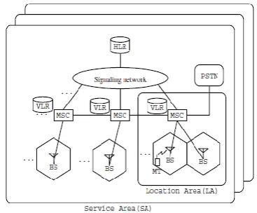
[image:1.595.336.520.267.419.2]The paper is organized as follows: Section 2 is the Literature Survey; Section 3 presents the Proposed Location management Scheme that clearly shows the Omni directional movement of mobile terminals from one LA to another LA. In Section 4, the analytical model of this scheme is presented followed by performance analysis and conclusions in Section 5 and Section 6 respectively.
Fig 1: A PCS Network
2. LITERATURE SURVEY
The feasible technique and the appropriate model description play an important role in location management [1] and thus various algorithms have been proposed to solve the problem faced in location management. To deal with the problem occurred in location management, two kinds of schemes have been proposed: static and dynamic [7]-[12]. The static location management defines the occurrence and frequency of location updates independently from any user characteristics. The proposed static location update schemes are : always update and never update. Such static mechanisms allow efficient implementation and low computational requirements due to lack of independent user tracking and parameterization. But this scheme has a drawback that MT is bounded or refuses for location registration. So without updating the location, users are free to move with a given LA informing that network when transitioning to a new LA. If a call is to be forwarded to a user, the network must page every cell within the location area to determine their exact location.
every ‘t’ time units where ‘t’ is the time threshold. Among above three schemes in dynamic location management scheme, distance based scheme gives the best results in terms of mobility and cost efficiency.
Many algorithms have been proposed to reduce the cost of involved in location updates and paging techniques. In IS – 41[2]-[3], MT initiates for location update. The Location update message is sent to the master HLR by current MSC. Once location registration is done in master HLR, it sends the acknowledgment to MT and then it results to the successful call delivery. A call is initiated by the MT and the base station (BS) forwards the call initialization signal to MSC. The MSC then sends a control to master HLR. The Master HLR checks the database for caller and transfer the call to serving MSC, MSC then delivers the call to suitable MT .In existing Location management only the master HLR of MTs accessed to control and locates the VLR. With the continuous growth of PCS subscribers, the access to master HLR and the associated volume of the signaling message increase respectively. In the continuous growth of MT, the network needs the pervasive communication for the moving MT. This situations strictly requires frequent location update and hence results more LU cost and congestion in HLR. In this paper; we proposed a mobility model based on dynamic VLR location management scheme for PCS network when the mobility is Omni directional.
3. PROPOSED LOCATION MANAGEMENT PROCEDURE
In this procedure, MT moves from one LA to another LA. MT initiates for the LU, and it sends LU message to serving MSC. The movement can be inter or intra. Through the movement of MT and corresponding BS signal’s behavior, current MSC predicts the previous LA. Current MSC sends the message to old VLR for forwarding the information about MT. The current VLR imports and store all information about the MT. The new MSC informs HLR that MT is residing in its serving area. So, Master HLR updates the LA information. HLR sends and acknowledgment to MT by serving MSC through successful registration. New MSC acknowledges to old MSC about new registration, thus old VLR deletes the information about MT. In implementation of this proposed scheme , firstly mobility is checked when MT moves left LA to right LA and right LA to left LA and secondly , reduction in signaling cost and location update cost is achieved; that results a tremendous improvement of system performance during implementation .
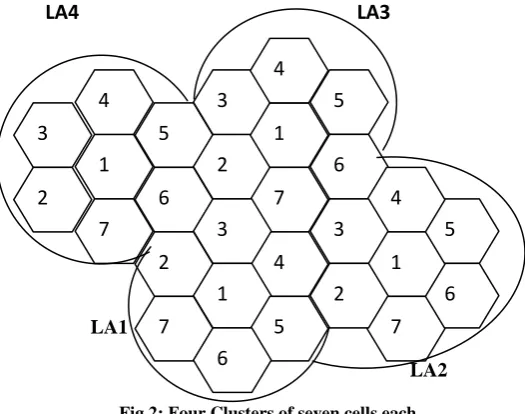
In the proposed scheme, the MT is moved in Omni direction manner i.e. left to right and right to left. Let us consider four clusters of cells as shown in Fig 2.
LA4 LA3
LA1
[image:2.595.293.556.73.280.2]LA2 Fig 2: Four Clusters of seven cells each.
The MT can enter into either LA1 or LA3 from LA4 as per assumption. Each LA contains seven cells as numbered from one to seven and these are also known as BS. There could be many possibilities: (a) a MT in LA4 can move within LA4; (b) a MT can move from LA4 to LA3 i.e. from left to right ;(c) a MT can move from LA4 to LA1 i.e. from right to left;(d) at same time, a MT at cell one in LA4 moves to LA1 in any of the cells and another MT at cell five in LA4 moves to LA3 in any of the cells . The cases (a),(b) and (c) are quite normal and can be achieved easily . But case (d) is Omni directional and also very feasible because here movement is traced out when MT moves in both the direction whether Left to Right or Right to Left. All the topologies must be recorded at MSC at each LA. The MSC contains a table called BS table. Seven BSs of single LA are associated with MSC. The BS table contains all the information about movement of MTs that actually tells the previous existence location of MTs. In Fig 2 let us have some assumptions; from BS-5 and BS-6 of LA4, it will come to BS-4 and BS-1 of LA3 respectively. Similarly from BS-2 and BS-4 of LA2, it will come to BS-3 and BS-5 of LA1 respectively. And BS-7 from LA2 comes to 5 at LA3. 7 form LA4 moves to 7 at LA1 and BS-3 form LA4 moves to BS-BS-3 at LA1.
TABLE 1: Base Station Table at MSC of LA3
Base Station
Its neighboring BSs of the same LA
Different LA on left hand side
1 2,3,4,5,6,7 LA4
2 X,X,3,1,7,X Nil
3 X,X,X,4,1,2 Nil
4 3,X,X,X,5,1 LA4
5 1,4,X,X,X,6 LA2
6 7,1,5,X,X,X Nil
7 X,2,1,6,X,X Nil
1
4
7
5
6
3
2
2
3
1
4
7
5
6
4
3
2
1
5
7
6
5
6
4
1
7
3
TABLE 2: Base Station Table at MSC of LA1
Base Station
Its neighboring BSs of the same LA
Different LA on right hand side
1 2,3,4,5,6,7 Nil
2 X,X,3,1,7,X Nil
3 X,X,X,4,5,1 LA2,LA4
4 3,X,X,X,5,1 Nil
5 1,4,X,X,X,6 LA2
6 1,5,X,X,X,7 Nil
7 X,2,1,6,X,X LA4
The BS table contains the information about the neighboring BSs of each BS and also left and right hand side of current LA with respect to particular BSs as shown in Table 1 and Table2. For example in Table 1 , BS-1 of LA3 is surrounded by six BSs of the same LA , hence the entry of all six BSs is shown in second column and third column is kept nil . The cross(X) tells that the BSs from another LA. When MT enters a new LA, it sends a LU message. The MSC checks the LU message, finds the associated BS and also checks the BS table to find out the right neighbors of that BS. If the BS is the boundary BS (whose first entry is X) of the LA, then the designed table helps MSC to search its previous LA.
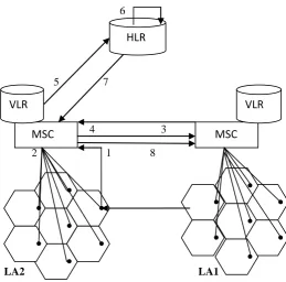
For example: When a MT moves from LA1 to LA2 as shown in Fig 3.
In the proposed scheme, the location update is performed as following steps :
(1) MT sends a LU message to associated MSC when it enters to new LA .
(2) The MSC checks the designed BS table and a
determines the previous LA, if any .
(3) The current MSC sends the request message to Old MSC, after the prediction of LA.
(4) Old MSC sends the details about MT to new MSC , the information about MT is stored in VLR of new MSC . (5) The current MSC update the records of MT and
forwards it to master HLR.
(6) The master HLR updates only new serving area of MT. (7) After successful update, the master HLR forwards an
acknowledgment to the MT via new MSC.
(8) The MSC sends acknowledgement message to Old MSC so that the old VLR deletes the data of MT.
4. ANALYTICAL MODEL
To study the performance of this scheme, an analytical model is designed based on [2]-[3]-[13].For the given MT, we define λm , λn be the incoming call arrival rates (i.e. average number of incoming calls per unit of time) from the same LA and from another LA respectively. Let us consider λp is the call arrival rate.
So,
λ
p =λ
m +λ
n,6
5 7
4 3
2 1 8
LA2 LA1 Fig 3: Location Update Process in Proposed Scheme. Now, the average LA existence time is denoted by 1/λa and inter movement probability time is presented by ‘n’. The values of 1/λa and ‘n’ tells the frequency and locality of the movements. We consider that the cost for a database query is equal to the cost of database update (HLR, VLR etc.). The above assumption is compromising since cost for a database query or update is much smaller than the communication cost and signaling cost. We denote cost for querying or update the HLR and VLR by Ch and Cv respectively. To determine the status of master HLR, let Cg be the cost for performing Global Title Transaction (GTT). Let the signaling cost for communication links in same LA and between two different LAs be Cl1 and Cl2 respectively. Without loss of generality, we assume that there is ‘M’ LA in a PCS network. Therefore 1/M is the possibility that a MT resides in any LA. Assuming signaling cost from MT to MSC is approximately half of Cl1 , the signaling cost between two MSC is also considered to be half of Cl1 . Therefore, the total signaling cost (S) for location registration,
S = S1 + S2 + S3 + S4 + S5 + S6
where,
S1= signaling cost between MT and current MSC.
=1/2 (Cl1)
S2 = signaling cost between current MSC and old
MSC (request for profile transfer)
=1/2 (Cl1)
MSC
MSC
HLR
[image:3.595.312.572.92.348.2]S3 = signaling cost between old MSC and current MSC (response of profile transfer request)
=1/2 (Cl1)
S4 = signaling cost between current MSC and master HLR
(updating location)
= Cl1
S5 = signaling cost between master HLR and MT.
= 1/2 (Cl1)
S6 = signaling cost between current MSC and old MSC
(acknowledgement). = 1/2 (Cl1)
S = 1/2(Cl1)+1/2(Cl1)+1/2 (Cl1) + Cl1
+1/2 (Cl1)+1/2(Cl1)
Therefore,S = 7/2 (Cl1).
In this scheme as discussed earlier, there are two possibilities and those are movement of MT is either intra LA or inter LA in which ‘n’ is the movement in intra LA and (1-n) is the movement in inter LA. The possibilities for the occurrence of these cases are (1/M), (1–1/M) respectively. Then total location update cost in proposed scheme is given by
CostLR=λa{(1-n)(S+3Cv+Ch)+(S+3Cv+Ch)
+Cg}
Therefore total signaling cost delivery in intra LA and inter LA is4Cl1 , (2Cl1 +2Cl2 ) respectively.
Cost per unit for call delivery in proposed scheme is CostCD= λm.(1/M)( 4Cl1 +2Cv+ Cg +Ch)
+λm(1– 1/M)( 2Cl1 +2Cl2 +2Cv+ Cg
+Ch)
CostLM = CostLR + CostCD
Where CostLM be the total cost per unit for proposed Location Management.
5. PERFORMANCE ANALYSIS
For the performance analysis, the data are taken directly from [2]-[13].
Let M=10; there are 10 LAs in the PCS network. n= 0.005(i.e. n=0.5%) at first time
The value of Cl1 should be smaller than Cl2
We consider the cases of Cl2 to study the effect of varying cost parameter.
Therefore, Cl2 = 3,4 and 5.
Assume Cv = 0.1, Ch =0.2, Cg = 0.3 because
Cv < Ch < Cg
Consider the case of incoming call arrival rates where λm = 1
and λn = 9
[image:4.595.320.523.245.408.2]The total LM cost is determined using above data with the help of previous formula derived. Call-to-mobility (CMR) is a ratio, which indicates the call arrival possibility with respect to user mobility.
Fig 4: Location Management Cost at λm = 1 and λn = 9
When CMR is low the mobility rate is high compared to the call arrival rate and this dominates the location registration cost. In this scheme, the λa and CMR are reciprocal to each other. When the value of λa is high (low CMR) then the total LM cost is increased. For satisfactory margin in LM cost value of CMR > 10-1 and at CMR ≤ 100; gives a almost constant differences of LM cost with different parameters of Cl2 = 3, 4, 5 (taken). The ratio of the total cost per unit time does not depend on the parameter of ‘n’.
[image:4.595.322.519.581.725.2]possibility, n, being 0.001, 0.011,0.021 as the value of CMR varies from 0.001 to 1000. These above analysis and yielded results show that the smaller inter LA movement probability results in a slightly lower relative cost.
6. CONCLUSIONS AND FUTURE
WORK
In our scheme, the location management cost will be reduced with a movement in MT. Analytical model of proposed scheme is justified for the mobility movement. The procedure is examined and analyzed for the Omni directional movement of MTs. The proposed scheme always reduces the location management cost and also traffic towards the HLR. The present challenges involved in updating location management welcomes further research and exploration to reduce the location management cost to fulfill the needs of fast and smooth communication in PCS Networks.
7. ACKNOWLEDGMENTS
I would like to thanks my guide Mr. S. P. Singh for his valuable support and secondly to my husband for appreciating me regarding this research work.
8. REFERENCES
[1] Guangbin Fan and Jingyuan Zhang, "A multi-layer location management scheme that bridges the best static scheme and the best dynamic scheme" , Proceedings of IEEE International Conference on Mobile Data Management, pp 125 - 132, 2004.
[2] Jie Li, Yi Pan and Yang Xiao, "A Dynamic HLR Location Management Scheme for PCS Networks", Proceedings of IEEE INFOCOM 2004 .
[3] Koteswararao Kondepu & Chiranjeev Kumar, "An Effective Pointer-Based HLR Location Registration Scheme in Location Management for PCS Networks," Proceedings of the First IEEE International Conference
on COMunication Systems and NETworks
(COMSNETS-2009), January 2009 .
[4] Jingyuan Zhang, "Location Management in cellular networks ," in handbook of wirele ss Networks and Mobile Computing, Edited by Ivan Stojmenovic, Jhon Wiely and Sons, pp.27-49, 2002.
[5] Yi-Bing Lin and Imrich Chlamtac, "GSM Mobility Management", in Wireless and Mobile Network Architecture, , Jhon Wiely and Sons, pp.l91-215, 2001. [6] Sanjay Kumar Biswash & Chiranjeev Kumar , "Distance
Direction-Probability Based Location Management Scheme for Wireless Cellular Network," Proceedings of the National Seminar on Recent Advances on Information Technology (RAIT- 2009) held at Indian School of Mines University (ISMU) , Dhanbad , pp. 30-38 , Feb 2009.
[7] Jun Zheng,Yan Zhang, Ling Wang, Jinlin Chen "Adaptive locat ion update area design for wireless cellular networks under 20 Markov walk model" Computer Communications, Volume 30, Issue 9, 30 June 2007, Pages 2060-2069
[8] Javid Taheri and Albert y.zomaya, "Bio-inspired Algorithms for Mobility Management", the International Symposium on Parallel Architectures, Algorithms, and Networks Proc IEEE 2008
[9] Xian Wang, Pingzhi Fan, Jie Li , and Yi Pan, "Modeling and Cost Analysis of Movement-Based Location Management for PCS Networks With HLR/VLR Architecture, General Location Area and Cell Residence Time Distr ibutions", IEEE Transaction on vehicular Technology, Vol. 57, No.6, Nov 2008
[10] Jeong, Eui-Jong; Lee, Goo-Yeon, "Efficient Location Management Scheme using MLR considering Local Usages", lING 07 Page(s):94I - 942, April 2007
[11] Beheshti B.D., "Review of Location Management in Cellular Networks", Proceedings of Systems , Applications and Technology Conference", LISAT 2007. IEEE Long Island 4-4 Page(s) : I - 6, May 2007
[12] Alejandro Quintero , Oscar Garcia, Samuel Pierre "An alternative strategy for location update and paging in mobile networks" Computer Communications, Volume 27, Issue 15,22 September 2004, Pages 1509-1523 [13]