GUIDE TO
STANDARDS AND
TOLERANCES 2015
2 VBA | GUIDE TO STANDARDS AND TOLERANCES 2015
FOREWORD
The Guide to Standards and Tolerances (the Guide) has been developed for use by builders and building owners as a convenient reference for acceptable standards of workmanship in domestic building construction. It is intended to address areas that are not prescribed under legislation or under a domestic building contract. Generally, parties to a building contract can agree on the standards they consider appropriate to their building project. Preferably, that agreed scope and standards of work is comprehensively detailed in the contract documents. Where it is not, there is risk of dispute at a later stage.
While the parties can agree on applicable standards, they cannot apply standards lower than those required by building regulation.
The content of this Guide is based on technical standards and industry tolerances that describe (or refer to) what is considered an acceptable standard of finished workmanship in domestic building construction.
It should be understood that this is a guide only and that all other documents prescribing statutory and contractual requirements, relevant to the contract, take precedence over this guide.
2
Acknowledgement
The Guide to Standards and Tolerances 2015 was produced by the Victorian Building Authority. All information, diagrams and materials included in this publication, except those expressly indicated as belonging to Standards Australia International Limited (SAIL), are the property of the Victorian Building Authority.
Diagrams and materials included in this publication, the copyright of which is owned by SAIL, have been reproduced by the VBA with the kind permission of the copyright owner and SAI Global Limited (SAI). For the reader’s convenience, we have indicated the relevant Australian Standard which references the diagram or materials in question. These are all available for purchase from SAI. For further information, please visit the SAI website at http://infostore.saiglobal.com/store/
Disclaimer
The content in this publication is provided for information purposes only. Although the Victorian Building Authority (VBA) believes that all information contained in this document is accurate and reliable as at the date of publication, the information must not be relied on or regarded as legal advice. The VBA provides no warranty about the accuracy, reliability or authenticity of any information or material contained in this publication, and accepts no liability whatsoever for direct or consequential loss or damage to any person in connection with the information or advice (or the use of such information or advice) which is provided in this publication or incorporated by reference. Information is provided on the basis that all persons accessing this publication or any materials referred to in it, do so at their own risk and undertake responsibility for assessing the relevance and accuracy of any and all content.
Copyright
Copyright © Victorian Building Authority.
Copyright in the content and design of this publication including all text, logos, diagrams and images, is owned by the Victorian Building Authority (except to the extent a different copyright owner is expressly identified in the publication).
Except in the limited circumstances set out in the Copyright Act 1968 (Cth), no part of this publication must be reproduced, copied, adapted, modified, communicated or otherwise used without written permission from the Victorian Building Authority (which may be withheld at the Victorian Building Authority’s absolute discretion).
4 VBA | GUIDE TO STANDARDS AND TOLERANCES 2015
CONTENTS
A Introduction 9
B Authority of the Guide 10
C Application of the Guide 11
D The measurement of time 11
E The measurement of tolerances 12
F Inspecting surfaces from a normal viewing position 14
G Remedial work 15
H Responsibility to rectify 15
I Renovations, alterations and extensions 16
J Recycled materials 16
K Building maintenance – Care of the building and site after completion 17 L Australian Standards and other referenced material 17 M Schedule of References used in this Guide 18
1 SITEWORKS (PAVING AND LANDSCAPING) 19
1.01 Cracking in concrete paving 19
1.02 Finish to external concrete paving 20
1.03 Surface drainage 20
2 FOOTINGS, SLABS AND SETTING OUT 21
2.01 Foundation and site drainage – maintenance after occupation 21
2.02 Footings and slabs 22
2.03 Setting out the site 22
2.04 External building dimensions 22
2.05 Measuring internal building dimensions 22
2.06 Building dimensions 22
2.07 Finished floor levels 23
2.08 Levelness of concrete floors 23
2.09 Dimensions of building elements 23
2.10 Cracks in concrete slabs 24
2.11 Finish to concrete slabs 24
2.12 Repairs to exposed concrete slabs 24
3 MASONRY 25
3.01 Masonry types 25
3.02 Damage to masonry walls 25
3.03 Movement; control joints in masonry walls 26
3.04 Masonry construction 26
3.05 Blending and matching of masonry – repair work 30
3.06 Blending and matching of masonry – new work 30
3.07 Masonry facing 31
3.08 Mortar for masonry 31
3.09 Voids and holes in mortar 31
3.10 Cracked masonry unit 31
3.11 Cleaning, mortar smears and stains 31
NEXT CHAPTER
PREVIOUS CHAPTER
3.12 Masonry inside garages and similar spaces and under applied finishes 31
3.13 Vertical alignment of perpend joints 31
3.14 Horizontal alignment of bed joints 32
3.15 Base bed joint and base row of masonry 32
3.16 Masonry that overhangs concrete slabs 32
3.17 Damp proof courses 32
3.18 Raking of joints 32
3.19 Brick sills, sill tiles and shrinkage allowance for timber framing 32
4 FRAMING 34
4.01 Verticality or plumbness of stumps or piles 34
4.02 Verticality or plumbness of steel and timber frames and exposed posts 34
4.03 Straightness of steel and timber frame surfaces 34
4.04 Packing under bearers 35
4.05 Timber shrinkage 35
4.06 Treads and risers in timber stairs 35
4.07 Fixing stud walls to concrete slabs 35
4.08 Bottom plates that overhang concrete slabs 36
5 WALL CLADDING 37
5.01 Leaks in wall cladding 37
5.02 Wall cladding 37
6 ROOFING 38
6.01 Leaks in roofing, flashings and accessories 38
6.02 Roof cladding 38
6.03 Roof tiles 38
6.04 Roof tile pointing 38
6.05 Overhang of roofing (tiles and sheet roofing) 39
6.06 Cutting of roof tiles 39
6.07 Dry valley construction 39
6.08 Undulating tiled roof lines 39
6.09 Alignment of trusses 40
6.10 Verticality or plumbness of trusses 40
7 PLUMBING 41
7.01 Plumbing 41
7.02 Positioning of gutters 41
7.03 Water retention in gutters 41
7.04 Joints in gutters 41
7.05 Fixing of gutters and downpipes 41
7.06 Flashings 41
7.07 Water hammer 45
7.08 Pipe penetrations through external walls and inside cupboards 45
7.09 Water supply fixtures 45
7.10 Water drainage from baths, basins, sinks, troughs or the like 45
CONTENTS
NEXT CHAPTER
PREVIOUS CHAPTER
6 VBA | GUIDE TO STANDARDS AND TOLERANCES 2015
8 WINDOWS AND DOORS 46
8.01 Installation of external windows and doors 46
8.02 Weather-tightness of windows, doors, and window and door frames 46
8.03 Door furniture 46
8.04 Internal door clearances 46
8.05 Distortion of doors 47
8.06 Sealing of door edges 47
8.07 Operation of windows and doors 47
8.08 Bowed window heads, sills and jambs 47
9 PLASTERING AND RENDERING 48
9.01 Verticality or plumbness of internal and external wall surfaces 48
9.02 Straightness of internal and external wall surfaces 48
9.03 Matching and repairing existing rendered surfaces 48
9.04 Cracking and other blemishes in rendered or hard plastered surfaces
on a masonry substrate 49
9.05 Repairs to applied finishes 49
9.06 Movement; Control joints – provision and cracking 49
9.07 Covering movement control joints and damp-proof courses 49
9.08 Cracking in applied finishes used over lightweight substrate 49
9.09 Rendered surfaces 49
9.10 Cracking in external mouldings 50
9.11 Plasterboard sheeting 50
9.12 Other sheeting systems 50
9.13 Level of finish for plasterboard 50
9.14 Cracking in plasterboard, hard plaster and other plaster elements 50
9.15 Cracking in cornices 51
9.16 Cracking at junctions of dissimilar materials 51
9.17 Straightness and alignment of plaster cornices 51
9.18 Peaking or jointing in plasterboard 51
9.19 Nail popping in surfaces 51
10 INTERNAL FIXING 52
10.01 Gaps associated with internal fixing 52
10.02 Joints in fixing of internal mouldings 52
10.03 Architrave quirks 52
10.04 Bench tops, cabinet doors and drawer fronts 52
10.05 Natural materials 52
10.06 Manufactured material 53
10.07 Rectification of defective natural materials and manufactured materials 53
10.08 Joints in timber, stone and laminated bench tops 53
10.09 Sealing around benches and items installed in benches 53
CONTENTS
CONTENTSNEXT CHAPTER
PREVIOUS CHAPTER
11 FLOOR AND WALL TILING 54
11.01 Floor and wall tiling 54
11.02 Floor and wall tiling where the builder supplies the tiles 54
11.03 Floor and wall tiling where the owner supplies the tiles for laying by the builder 54 11.04 Floor and wall tiles where the owner supplies and lays the tiles 54
11.05 Cracked, pitted, chipped, scratched or loose tiles 54
11.06 Grouting and joints 55
11.07 Flexible sealants to junctions 55
11.08 Uneven tiling 55
11.09 Lippage (stepping) between tiles 56
11.10 Movement joints 56
12 PAINTING 57
12.01 Standard of painting 57
12.02 Surface finish of paintwork 57
12.03 Nail and screw fixings 57
12.04 Natural characteristics and mechanical imperfections/damage 57
12.05 Paint durability 57
13 WET AREAS, DECKS AND BALCONIES 58
13.01 General 58
13.02 Wet areas 58
13.03 Shower recess and components 58
13.04 Leaks in waterproof decks and balconies 58
13.05 Waterproof decks and balconies substrate 59
13.06 Decks and balcony freeboard outside windows and doors 59
13.07 Ponding on waterproof decks and balconies 59
13.08 Calcification and efflorescence associated with decks and balconies 59
14 FLOORS 60
14.01 Timber flooring – shrinkage and swelling 60
14.02 Timber flooring 60
14.03 Gaps in exposed timber flooring 60
14.04 Joint swelling in timber, plywood and particleboard flooring 60
14.05 Nail popping in timber, plywood and particleboard floors 61
14.06 Squeaking floors 61
14.07 Springy floors 61
14.08 Levelness of timber floor 61
14.09 Splitting of timber decking 61
15 ELECTRICAL 62
15.01 Electrical 62
CONTENTS
NEXT CHAPTER
PREVIOUS CHAPTER
8 VBA | GUIDE TO STANDARDS AND TOLERANCES 2015
16 POOLS AND SPAS 63
16.01 Concrete pools and spas 63
16.02 Premoulded fibre-reinforced plastic pools and spas 63
16.03 Variations from documented dimensions in concrete pools and spas 63
16.04 Variations from documented datum in concrete pools and spas 63
17 RESTUMPING 64
17.01 Restumping 64
17.02 Consequential damage due to restumping 64
17.03 Floor levels after restumping 64
18 GENERAL 65
18.01 Appliances and fittings 65
18.02 Faults and damage to appliances and fittings 65
18.03 Condensation 65
18.04 Glazing 65
18.05 Lyctus borer 65
18.06 Termites 66
18.07 Termite damage 66
18.08 Cleaning 66
18.09 Maintenance in relation to the performance of building foundations/footings 66
18.10 Floor coverings 68
Appendix A 69
Relevant legislation 69
History of editions 69
CONTENTS
CONTENTSNEXT CHAPTER
PREVIOUS CHAPTER
Every year thousands of homes are constructed or renovated in Victoria. While most building projects are completed successfully, occasionallythere may be concerns or unmet expectations that result in a dispute.
Most domestic building disputes arise because of disagreements betweenbuilding owners and builders about the appropriate standards and quality of work. Although the minimum standards for some aspects of construction are regulated, many aspects are not.
Builders and building owners can help prevent disputes by agreeing on the standards and quality of workmanship appropriate for the project when they enter into the building contract, although they cannot apply standards lower than those regulated by Government. However, many domestic building contracts don’t include an agreed scope of work and standards. The Guide to Standards and Tolerances 2015 (the Guide) has been developed for builders and building owners to use as a convenient reference to the minimum technical standards and quality of work. The Guide provides references to relevant areas of legislation and gives guidance on areas of building standards that are not covered by legislation. Building work that does not meet the standards outlined in the Guide could be considered defective. The Guide can be used to help resolve disputes about the quality and standards of work. However, it should be understood that this document is intended as a guide only, all other documents stating statutory and contractual requirements take precedence over this Guide.
A
INTRODUCTION
CONTENTS
NEXT CHAPTER
PREVIOUS CHAPTER
10 VBA | GUIDE TO STANDARDS AND TOLERANCES 2015
B
AUTHORITY OF THE GUIDE
Each state and territory has legislated to empower the making of building standards and to control the key elements of a domestic building contract.
Regulated building standards are predominantly contained within the National Construction Code Series, Volumes 1 and 2, Building Code of Australia (BCA) which is adopted into law by regulation. In a hierarchy, the regulatory framework for building standards starts with the relevant Act of Parliament or Legislative Assembly, passes to regulations made under that Act, then to the BCA, to Australian Standards and other documents adopted by reference in the BCA.
The Guide to Standards and Tolerances 2015 is only a guide and an advisory document. It is not a regulated standard and is not part of this hierarchy.
Each state and territory has an Act to regulate the contents of a domestic building contract and the responsibilities of parties. These Acts also require compliance with regulated building standards and require buildings and their materials to be fit for their intended purposes. In Victoria, the Domestic Building Contracts Act 1995 defines the term ‘defective’ as:
“ In relation to domestic building work, includes: a) a breach of any warranty listed in section 8
b) a failure to maintain a standard or quality of building work specified in the contract.” This Guide can be used to determine whether or not an item is defective only where this cannot be done by reference to the contract documents, the relevant Australian Standards, the BCA or the relevant regulations. Where there is any contradiction or difference between the Guideand an Act, a regulation, the BCA or a building contract, all of these take precedence over the Guide. The Guidedoes not replace the
requirements of these other documents.
Any reference throughout this document to the Building Code of Australia or BCA refers to the National Construction Code Series, Volumes 1 and 2, Building Code of Australia. Some Australian Standards are referred to (whole or in part) in the BCA. The referenced parts of these Australian Standards take precedence over this Guide.
Fittings, equipment and some materials used in buildings are often supported by manufacturer’s installation instructions. The manufacturer’s installation instructions take precedence over this Guide.
CONTENTS
NEXT CHAPTER
PREVIOUS CHAPTER
C
APPLICATION OF THE GUIDE
The Guideis intended to inform parties as to what is an acceptable standard of workmanship in domestic building work. It should be noted that builders, subsequent owners and those purchasing from owner-builders or developers can also use this Guide to resolve possible disputes, irrespective of whether or not they were a party to the original building contract.
This edition of the Guide is valid from 30 March 2015 and is applicable to domestic building contracts entered into from that date, or domestic building work that commences from that date (where there is no domestic building contract).
D
THE MEASUREMENT OF TIME
Any time period mentioned in the Guideis to be taken to start at the date of completion of the building work as it is legislated in the state or territory where the building work is located. Generally, the date of completion is the day when the work carried out under the contract is completed in accordance with the terms of that contract, or the day the building owner is given the statutory permit (i.e. Occupancy Permit) or certificate (i.e. Certificate of Final Inspection) that authorises the occupation or use of the building. A more precise definition should be given in the contract associated with the building work.
CONTENTS
NEXT CHAPTER
PREVIOUS CHAPTER
12 VBA | GUIDE TO STANDARDS AND TOLERANCES 2015
E
THE MEASUREMENT OF TOLERANCES
The tolerances in this Guideapply up to and including the length over which each tolerance is stated to apply. It is not intended that tolerances will be interpolated or proportioned to the actual length of building element measured. For example, where the Guide specifies a 4 mm maximum deviation measured over a 2 m length of wall surface, the Guide means that the same 4 mm deviation is to be applied over a 1 m wall surface or a 500 mm wall surface. The tolerance cannot be interpolated to mean a 2 mm deviation over a 1 m wall surface or 1 mm deviation over a 500 mm wall surface. Similarly, deviations over longer wall surfaces would be defects if the deviation exceeded 4 mm within any 2 m length of that surface. Horizontal, vertical and diagonal surface tolerances are to be interpreted in the same way.
Horizontal surfaces
Deviations of a horizontal surface are to be measured from a datum nominated in the contract documents or inferred, if none is nominated. Where there is a nominated or inferred datum, the maximum deviation from that datum will not exceed the deviation stated in the Guide. Where no datum is nominated and a datum cannot be inferred, a datum level will be taken to be at the highest or lowest points in the building element, room or area being measured. Refer to diagram E(i).
Horizontal flatness to be measured as shown in Diagrams E(ii) and (iii).
Vertical surfaces
Deviations of a vertical surface from a true vertical plane are to be measured from a plumb line through a plan position or reference point nominated in the contract documents or inferred, if none is nominated. The maximum deviation of a vertical surface from that plumb line will not exceed the deviation stated in the Guide. Refer to diagram E(iv). Vertical flatness to be measured as shown in Diagrams E(v) and (vi).
Where diagrams are provided for the clarification of details, the diagram shows only detail relevant to the issue and is not intended to be used as a general detail for construction.
CONTENTS
NEXT CHAPTER
PREVIOUS CHAPTER
Spirit level
BASE OF WALL Surface being tested Maximum deviation
VER
TICAL
PLUMB LINE
Surface being tested
Straight edge
BASE OF WALL Maximum
deviation
Equal HT spacers
Maximum deviation
BASE OF WALL
Straight edge to be centred over bow
iv) Measurement of
deviation from v) Measurement of bow vi) Measurement of bow
Surface being tested
HORIZONTAL LEVEL LINE Spirit level
Maximum deviation
Surface
being tested Maximumdeviation Straight edge
Equal height packing
to both ends being testedSurface Maximumdeviation Straight edge
DIAGRAM E
MEASUREMENT OF HORIZONTAL TOLERANCES
DIAGRAM E
MEASUREMENT OF VERTICAL AND INCLINED SURFACES
iii) Measurement of bow(horizontal flatness) ii) Measurement of bow i) Measurement of
deviation from horizontal/level
CONTENTS
NEXT CHAPTER
PREVIOUS CHAPTER
14 VBA | GUIDE TO STANDARDS AND TOLERANCES 2015
F
INSPECTING SURFACES FROM
A NORMAL VIEWING POSITION
Generally, variations in the surface colour, texture and finish of walls, ceilings, floors and roofs, and variations in glass and similar transparent materials are to be viewed where possible from a normal viewing position. A normal viewing position is looking at a distance of 1.5 m or greater (600 mm for appliances and fixtures) with the surface or material being illuminated by ‘non-critical light’1. Non-critical light means the light that strikes the surface is diffused and is not glancing or parallel to that surface.
DIAGRAM F
NORMAL VIEWING POSITIONS
Slight variations in the colour and finish of materials do not always constitute a defect.
1 Non-critical light is defined in appendix.B3 and D7 Australian Standard AS/NZS 2589. Refer also to CSIRO TR 90/1, Report No. L8 – 1992.
1500 mm
W
all
1500 mm
Floor
1500 mm
Ceiling
600 mm
Viewing fixtures and appliances CONTENTS
NEXT CHAPTER
PREVIOUS CHAPTER
G
REMEDIAL WORK
It is envisaged that work to rectify defects will be carried out to match as closely as practical the surrounding materials, finishes, levels and other characteristics of the area to be rectified. In some circumstances, exact matching may not be possible.
Structural rectification work may need to be designed by a structural engineer and inspected or certified by a building surveyor or certifier.
Some remedial work may need to be agreed by way of a contract variation and variation to a building permit or construction certificate before it is carried out.
H
RESPONSIBILITY TO RECTIFY
A builder may not be liable to rectify building design and defects that do not arise from the builder’s or the builder’s subcontractor’s work and design. Builders do not have to rectify damage caused by the owner’s actions or those of other people engaged by the owner. Builders may be liable to repair damage caused to property in the course of completing their building work.
The following are examples of liability between the owner and the builder:
a) A builder is unlikely to have to repaint a poorly painted wall that was painted by the building owner.
b) A builder is unlikely to have to repair a distorted gutter when the damage was caused by an owner placing a ladder against the gutter.
c) A builder is unlikely to have to repair a stormwater drain that was properly constructed and later blocked by tree roots.
d) A builder is likely to have to replace untreated pine in an external deck that was installed by the builder instead of the durable timber required for this structure.
e) A builder is likely to have to repair an existing window in a house that the builder accidentally damaged when constructing another part of the house.
Where there is subsequent damage to the building due to defective building work as a result of the:
a) owner failing to keep the completed work reasonably maintained, or
b) unreasonable delay by the owner in notifying the builder of the defect, the builder may not be liable to rectify or compensate the owner.
Where reference is made in the Guide to the ‘builder’s workmanship’, ‘work of the builder’ or the like, this includes work by contractors or sub-contractors engaged by the builder. In Victoria, the Domestic Building Contracts Act 1995 defines the term ‘builder’ as being:
“ A person who, or a partnership which: a) carries out domestic building work; or
b) manages or arranges the carrying out of domestic building work; or c) intends to carry out, or to manage or arrange the carrying out of,
CONTENTS
NEXT CHAPTER
PREVIOUS CHAPTER
16 VBA | GUIDE TO STANDARDS AND TOLERANCES 2015
I
RENOVATIONS, ALTERATIONS AND EXTENSIONS
The standards and tolerances in this Guide only apply to the work covered in the relevant domestic building contract.
It is recommended that before starting new work, the builder informs the owner of any potential circumstances and conditions of the existing building that may have a detrimental effect on the standard of the new building work.
The builder and owner should agree as part of their domestic building contract, or as a written variation to that contract, on the extent of any necessary rectification works that may be required to be carried out to the existing building before commencing that work.
J
RECYCLED MATERIALS
The standards and tolerances in this Guide may not apply to construction with hand or recycled materials and products. Where there is a contract, the use of second-hand or recycled material must be stated in that contract. Second-second-hand or recycled materials and products must be fit for purpose and suitable for its’ proposed use.
CONTENTS
NEXT CHAPTER
PREVIOUS CHAPTER
K
BUILDING MAINTENANCE – CARE OF THE BUILDING
AND SITE AFTER COMPLETION
Building maintenance is an ongoing responsibility for all building owners to ensure their building continues to perform as intended.
Therefore it is recommended owners consider the information in Explanatory Note 2A at the start of Section 2 of this Guide. These documents and other similar documents discuss soil movement and its effects on buildings, including the effects of tree planting and site drainage. Owners can reduce the risk of cracking and damage to building structures by adopting the landscape care suggestions in these documents.
Refer to the following within this Guide: a) Explanatory Note at the start of Section 2
b) Clause 2.01 – Foundation and site drainage – maintenance after occupation c) Clause 18.09 – Maintenance.
L
AUSTRALIAN STANDARDS
AND OTHER REFERENCED MATERIAL
Where this Guide refers to Australian Standards or other reference material, the edition referred to is the one that was current at the time the contract was signed. In many cases this will be a document referred to in the Building Code of Australia that was current at that time.
Where a contract specifies an alternative reference to the ones listed over the page, that reference may be applicable to the work. However, this does not override any statutory obligations to comply with the building legislation.
CONTENTS
NEXT CHAPTER
PREVIOUS CHAPTER
18 VBA | GUIDE TO STANDARDS AND TOLERANCES 2014
M
SCHEDULE OF REFERENCES USED IN THIS GUIDE
BCA 2014 National Construction Code Series, Volumes 1 and 2, Building Code
of Australia (BCA)
AS 1684–2010 Residential timber-framed construction
AS 1860.2–2006 Particleboard flooring – Installation
AS 2047–1999 Windows in buildings – Selection and installation
AS 2783–1992 Use of reinforced concrete for small swimming pools
AS 2796.1–1999 Timber – Hardwood – Sawn and milled products
AS 2870–2011 Residential slabs and footings
AS 3598.1–2007 Ceramic tiles – Part 1: Guide to the installation of ceramic tiles
AS 3598.2–2007 Ceramic tiles – Part 2: Guide to the selection of a ceramic tiling system AS 3660.2–2000 Termite management – Part 2: In and around existing buildings and
structures – Guidelines
AS 3700–2011 Masonry structures
AS 3727–1993 Guide to residential paving
AS 3740–2010 Waterproofing of domestic wet areas
AS 4654–2012 Waterproofing membranes for external above-ground use
AS 4773.2–2010 Masonry in small buildings – Construction
AS/NZS 1839–1994 Swimming pools – Premoulded fibre-reinforced plastics – Installation AS/NZS 2311–2009 Guide to the painting of buildings
AS/NZS 2589–2007 Gypsum linings – Application and finishing
AS/NZS 3500.3–2012 Plumbing and drainage – Part 3: Stormwater drainage AS/NZS 4386.1–1996 Domestic kitchen assemblies – Kitchen units
CSIRO document
BTF17–2011 Building Technology File 17 – Plant roots in drains – Prevention and cure CSIRO document
BTF18–2011 Building Technology File 18-2011 – Foundation maintenance and footing performance: A homeowner’s guide CSIRO document
BTF19–2011 Building Technology File 19 – A builder’s guide to preventing damage to dwellings: Part 1 – Site investigation and preparation CSIRO document
BTF22–2008 Building Technology File 22 – A builder’s guide to preventing damage to dwellings: Part 2 – Sound construction method CSIRO TR 90/1, Report
No. L8–1992 CSIRO Division of Building Research Report No TR 90/1 : Illumination and decoration of flat surfaces – 5th Edition (Revised)
ABCB Handbook Condensation in Buildings (2014)
www.abcb.gov.au/en/education-events-resources/publications /abcb-handbooks.aspx
18 VBA | GUIDE TO STANDARDS AND TOLERANCES 2015
CONTENTS
NEXT CHAPTER
PREVIOUS CHAPTER
SITEWORKS (P
AVING AND LANDSCAPING)
1
1
SITEWORKS (PAVING AND LANDSCAPING)
1.01
Cracking in concrete paving
Cracking in concrete is common and is not always attributable to unsatisfactory
workmanship. Common causes of cracking include shrinkage stress, stress due to trees, commercial or heavy vehicle traffic, soil movement due to changes in the moisture content as a result of garden watering or drainage problems.
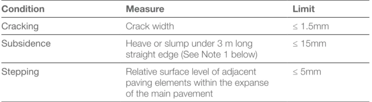
Cracking not attributable to the workmanship of the builder (e.g. trees planted too close to paving, commercial or heavy duty vehicle traffic, use of sprinkler system, etc.) is not a defect. Cracking in concrete verandahs, garages, carports, paving, patios, driveways, etc. where the builder did not make allowances for shrinkage or general movement of the concrete (e.g. slip joints where required around penetrations such as verandah posts, pipes etc.) shall be assessed in accordance with Table 1.01and is defective where the limits in that table are exceeded.
TABLE 1.01
CRACKS IN CONCRETE PAVING
Condition Measure Limit
Cracking Crack width ≤ 1.5mm
Subsidence Heave or slump under 3 m long
straight edge (See Note 1 below) ≤ 15mm
Stepping Relative surface level of adjacent paving elements within the expanse of the main pavement
≤ 5mm
Taken from: AS 3727 – Guide to residential pavements, Table: 1 Performance criteria. Reproduced with
permission from SAI Global Ltd under Licence 1407-c122.
Notes to Table 1.01
1. The straight edge is centred over the defect and supported at its ends by equal height spacers. The heave or slump is then measured relative to this straight edge.
2. The stepping criteria apply only to steps within the surface of the main pavement. It shall not be applied where the main pavement abuts other structures such as edging, drainage pits, service pits, minor pavements (such as a pathway adjacent to a driveway) and pavements constructed with materials of a different type.
3. The performance criteria in Table 1.01 apply within the first 12 months after construction of the pavement.
4. The builder may be responsible for works after 12 months if not constructed in accordance with the standard (AS3727).
5. The 12-month period has been adopted as being long enough for a pavement to be subjected to in-service conditions and prior to undue influence of changing environmental conditions such as the effect of tree roots.
CONTENTS
NEXT CHAPTER
PREVIOUS CHAPTER
20 VBA | GUIDE TO STANDARDS AND TOLERANCES 2015
1.02
Finish to external concrete paving
Concrete paving finish is defective if it is not consistent in colour, texture and general
appearance. Minor variations in finish may occur and may not be considered to be defective.
1.03
Surface drainage
The paving/landscaping should direct surface water away from the building. Surface water drainage is defective if it is not in accordance with the requirements of the Building Code of Australia.
SITEWORKS (P
AVING AND LANDSCAPING)
1
CONTENTS
NEXT CHAPTER
PREVIOUS CHAPTER
2
FOOTINGS, SLABS AND SETTING OUT
2
FOOTINGS, SLABS AND SETTING OUT
Explanatory Note 2A:
Footing systems and movement
Footing systems for residential buildings (new buildings or extensions) are designed and constructed according to the building legislation, site-specific soil classification, site conditions and requirements of the development; and can be adversely affected by many factors.
A footing system designed within these parameters is expected to move within acceptable limits to cope with the site-specific conditions. This movement may result in minor distress to the building, including cracking and gaps to the floors, walls and ceiling.
Therefore, distress can only be apportioned to the builder where the distress exceeds the tolerances specified in the Guide as a result of the builder’s workmanship.
Abnormal moisture conditions causing building distress may be the result of many contributing factors including:
• landscaping and tree types and proximity • excessive and localised watering of gardens • poor building/site maintenance
• water leaks (gutters, pipes and appliances) • adverse effects from adjoining properties.
Causes of building distress are often difficult to identify and explain, and on occasion it is difficult to identify the responsible party or parties.
Further information on foundation systems and movement can be found in the following reference material:
• CSIRO Document – Building Technology File 17 – Plant roots in drains – Prevention and cure • CSIRO Document – Building Technology File 18-2011 – Foundation maintenance and footing
performance: A homeowner’s guide
• CSIRO Document – Building Technology File 19 – A builder’s guide to preventing damage to dwellings: Part 1 – Site investigation and preparation
• CSIRO Document – Building Technology File 22 – A builder’s guide to preventing damage to dwellings – Part 2 – Sound construction method
• Australian Standard 2870–2011: Residential slabs and footings.
2.01
Foundation and site drainage – maintenance after occupation
The builder is not responsible for foundation movement caused by activities that were not documented at the time of entering into the contract or as variation to that contract, or that are undertaken by the owner. These include paving, landscaping, planting trees and drainage works after the site is handed over to the owner.
The builder is not responsible for foundation movement caused by the owner’s failure to maintain drainage systems after the site is handed over to the owner.
Refer also to Item K of this Guide.
CONTENTS
NEXT CHAPTER
PREVIOUS CHAPTER
22 VBA | GUIDE TO STANDARDS AND TOLERANCES 2015
2.02
Footings and slabs
Slabs and footings are defective if they fail because they are not designed and constructed in accordance with the Building Code of Australia or AS 2870.
Slabs and footings are defective where foundation movement is caused by factors that were present during construction (e.g. poor founding material, excessive wetting and drying of site, number, type proximity and maturity of trees/shrubs or lack of site drainage). Slab and footing movement should be assessed in accordance with Table 2.10 and Table 3.02 of this Guide.
2.03
Setting out the site
A building set out is defective where the set out has failed to comply with the requirements of the approved drawings, the allotment Certificate of Title, planning or development approval, relevant planning overlays and schemes and building regulations.
Building work must not encroach over an allotment boundary unless authorised/approved to do so. A builder must ensure footings, gutters and any other part of the building work does not encroach an allotment boundary unless authorised/approved to do so.
2.04
External building dimensions
Departures from documented external dimensions of buildings are defects if they exceed L/200 where L is the documented overall length of wall, or 5 mm, whichever is the greater.
2.05
Measuring internal building dimensions
Unless shown otherwise, dimensions shown on drawings for internal walls always refer to the structure’s dimensions. Structure means masonry and timber framing and does not include finishes such as plasterboard, render and skirtings. The internal room sizes will be different when thicknesses of internal finish materials are taken into account.
2.06
Building dimensions
Departures from the documented set out for service rooms such as bathrooms, toilets, laundries, kitchens etc. are defects if they exceed L/200 or 5 mm, whichever is the greater, where L is the documented dimension.
Departures from the documented set out for habitable rooms and areas, such as bedrooms, dining rooms, lounge and living rooms, family rooms, studies, halls, entries and stairways are defects if they exceed L/100 or 5 mm, whichever is the greater, where L is the documented dimension.
Departures from documented set out for external elements such as garages, carports, verandahs, decks, patios, etc. are defects if they exceed L/100 or 5 mm, whichever is the greater, where L is the documented dimension. Masonry work shall comply with Table 3.04. The set out is defective where a specific fixture or feature is required to be accommodated, and such documented dimensions to accommodate that fixture or feature are not provided. Ceiling heights shall be in accordance with the requirements of the Building Code of Australia, unless a greater height is specified in the contract.
2
FOOTINGS, SLABS AND SETTING OUT
CONTENTS
NEXT CHAPTER
PREVIOUS CHAPTER
2
FOOTINGS, SLABS AND SETTING OUT
2.07
Finished floor levels
Finished floor levels (FFL) or reduced levels (RL) are defective where they do not comply with specified planning and/or building permit requirements.
In other cases, FFL or RL are defective where:
a) they depart from the documented RL or FFL by more than 40 mm; or
b) floors are documented to be on the same plane but are constructed on different planes; or
c) the building work is an extension or addition and new floor levels do not match the existing building floor levels. Also refer to Item I of this Guide.
2.08
Levelness of concrete floors
Except where documented otherwise, new floors are defective if within the first 24 months of handover they differ in level by more than 10 mm in any room or area, or more than 4 mm in any 2 m length. The overall deviation of floor level to the entire building footprint shall not exceed 20 mm. Refer to Item I of this Guidewhere the new floor is to abut an existing floor.
2.09
Dimensions of building elements
Deviations from the documented height or cross-sectional dimension of building elements such as beams and posts are defective if they exceed L/200 where L is the documented dimension or 5 mm, whichever is the greater.
CONTENTS
NEXT CHAPTER
PREVIOUS CHAPTER
24 VBA | GUIDE TO STANDARDS AND TOLERANCES 2015
2.10
Cracks in concrete slabs
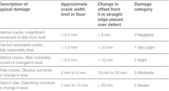
Refer to Table 2.10 for descriptions of categories of cracks. Cracks to slabs are defective where they are Category 3 and 4.
Category 1 and 2 cracks to slabs are to be monitored for a period of 12 months. At the end of the monitoring period, cracks are defective if they are greater than category 2 and attributed to the actions of the builder.
TABLE 2.10
CLASSIFICATION OF DAMAGE TO CONCRETE FLOORS
Description of
typical damage Approximate crack width limit in floor
Change in offset from 3 m straight edge placed over defect
Damage category
Hairline cracks, insignificant
movement of slab from level < 0.3 mm < 8 mm 0 Negligible Fine but noticeable cracks.
Slab reasonably level < 1.0 mm < 10 mm 1 Very slight
Distinct cracks. Slab noticeably
curved or changed in level < 2.0 mm < 15 mm 2 Slight Wide cracks. Obvious curvature
or change in level 2 mm to 4 mm 15 mm to 25 mm 3 Moderate
Gaps in slab. Disturbing curvature
or change in level 4 mm to 10 mm > 25 mm 4 Severe
Taken from AS 2870: Residential slabs and footings – Construction, Table C2: Classification of damage
with reference to concrete floors. Reproduced with permission from SAI Global Ltd under Licence 1407-c122.
Notes to Table 2.10
1. The straightedge is centred where possible over the defect, and supported at its ends by equal height spacers. The change in offset is then measured relative to this straightedge, which is not necessarily horizontal.
2. Local deviation of slope, from the horizontal or vertical, of more than 1:100 will normally be clearly visible. Overall deviations in excess of 1:150 is undesirable.
3. Account should be taken of the past history of damage in order to assess whether it is stable or likely to increase.
2.11
Finish to concrete slabs
The finish to a concrete slab is defective if it is not suitable for the documented applied finishes such as tiles, polished concrete, carpet or sheet flooring, including set downs where required.
2.12
Repairs to exposed concrete slabs
Repairs, where failure has been due to cracking and/or movement, may involve the removal of the affected area. The repair is defective if it does not, as closely as practicable match the existing work in appearance, colour and texture. Minor variations in finish may not be considered to be defective.
2
FOOTINGS, SLABS AND SETTING OUT
CONTENTS
NEXT CHAPTER
PREVIOUS CHAPTER
3
MASONR
Y
3 MASONRY
3.01
Masonry types
This section includes tolerances for generally-used types of masonry, including: a) clay and concrete brick construction
b) clay and concrete brick veneer construction c) concrete block construction.
The tolerances for the above may not always be appropriate for some types of masonry construction, such as pre-fabricated masonry panels, aerated concrete blocks, irregular cut stone, rustic finish masonry with irregular edges and appearance, etc. In these cases, parties must obtain the manufacturer’s advice.
3.02
Damage to masonry walls
Refer to Table 3.02 for descriptions of categories of damage.
Category 3 or greater damage to walls is defective and requires investigation, stabilisation, monitoring and rectification work, which may include breaking out and replacing sections of the wall.
Category 2 cracks to walls are to be monitored for a period of 12 months. At the end of the monitoring period, a crack rated at Category 2 or above is defective and requires rectification. Category 2 damage is defective and requires minor repair work such as repointing.
TABLE 3.02
DAMAGE TO WALLS CAUSED BY MOVEMENT OF SLABS
AND FOOTINGS AND OTHER CAUSES
Description of typical
damage and required repair Crack width limit Damage Category
Hairline cracks < 0.1 mm 0 Negligible
Fine cracks that do not need repair < 1 mm 1 Very slight
Cracks noticeable but easily filled. Doors and windows stick slightly
< 5 mm 2 Slight
Cracks can be repaired and possibly a small amount of wall will need to be replaced. Doors and windows stick. Service pipes can fracture. Weather tightness often impaired
5 mm to 15 mm (or a number of cracks 3 mm or more in one group)
3 Moderate
Extensive repair work involving breaking-out and replacing sections of walls, especially over doors and windows. Window and doorframes distort. Walls lean or bulge noticeably. Some loss of bearing in beams. Service pipes disrupted
15 mm to 25 mm but also depends on number of cracks
4 Severe
Taken from AS 2870: Residential slabs and footings – Construction, Table C1: Classification of damage with reference to walls. Reproduced with permission from SAI Global Ltd under Licence 1407-c122.
Notes to Table 3.02
1. Where the cracking occurs in easily repaired plasterboard or similar clad-framed partitions, the crack width limits may be increased by 50 per cent for each damage category.
CONTENTS
NEXT CHAPTER
PREVIOUS CHAPTER
26 VBA | GUIDE TO STANDARDS AND TOLERANCES 2015
3.03
Movement; control joints in masonry walls
Where required, control joints are defective if not installed as required by the Building Code of Australia or in accordance with the contract documents.
Control joints are defective if they do not extend through the full thickness of masonry skin. Where required, control joints are defective if they are not sealed in accordance with AS 3700.
Unless documented otherwise, flexible mastic or sealant is defective if it does not match as close as practicable the colour of the adjacent surface, and has not been applied in accordance with the manufacturer’s installation instructions.
3.04
Masonry construction
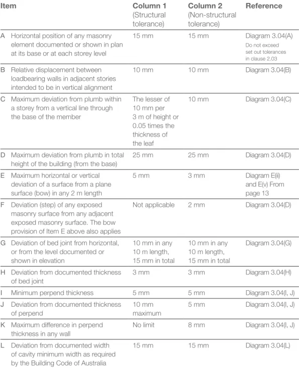
Masonry is defective if it exceeds the tolerances set out in Table 3.04.
3
MASONR
Y
CONTENTS
NEXT CHAPTER
PREVIOUS CHAPTER
MASONR
Y
3
TABLE 3.04
TOLERANCES IN MASONRY CONSTRUCTION
Item Column 1
(Structural tolerance) Column 2 (Non-structural tolerance) Reference
A Horizontal position of any masonry element documented or shown in plan at its base or at each storey level
15 mm 15 mm Diagram 3.04(A)
Do not exceed set out tolerances in clause 2.03
B Relative displacement between loadbearing walls in adjacent stories intended to be in vertical alignment
10 mm 10 mm Diagram 3.04(B)
C Maximum deviation from plumb within a storey from a vertical line through the base of the member
The lesser of 10 mm per 3 m of height or 0.05 times the thickness of the leaf
10 mm Diagram 3.04(C)
D Maximum deviation from plumb in total height of the building (from the base)
25 mm 25 mm Diagram 3.04(D)
E Maximum horizontal or vertical deviation of a surface from a plane surface (bow) in any 2 m length
5 mm 3 mm Diagram E(ii)
and E(v) From page 13
F Deviation (step) of any exposed masonry surface from any adjacent exposed masonry surface. The bow provision of Item E above also applies
Not applicable 2 mm Diagram 3.04(D)
G Deviation of bed joint from horizontal, or from the level documented or shown in elevation
10 mm in any 10 m length, 15 mm in total
10 mm in any 10 m length, 15 mm in total
Diagram 3.04(G)
H Deviation from documented thickness of bed joint
3 mm 3 mm Diagram 3.04(H)
I Minimum perpend thickness 5 mm 5 mm Diagram 3.04(I, J)
J Deviation from documented thickness of perpend
10 mm maximum
5 mm Diagram 3.04(I, J)
K Maximum difference in perpend thickness in any wall
No limit 8 mm Diagram 3.04(I, J)
L Deviation from documented width of cavity minimum width as required by the Building Code of Australia
15 mm 15 mm Diagram 3.04(L)
Taken from AS 3700 – Masonry structures, Table 12.1: Tolerances in masonry construction. Reproduced with
permission from SAI Global Ltd under Licence 1407-c122.
Notes to Table 3.04
1. Items H, I, J and K are not applicable to thin-bed mortar joints.
2. Items I and J tolerances are not applicable when perpend joints are not filled with mortar as is the case with some horizontally cored masonry that is not required to resist horizontal bending. 3. Items E, F and I only apply to the true, fair or finish face of single skin masonry.
4. For structural tolerances in masonry refer to the Building Code of Australia. 5. The tolerances within the table apply to each separate masonry panel face.
CONTENTS
NEXT CHAPTER
PREVIOUS CHAPTER
28 VBA | GUIDE TO STANDARDS AND TOLERANCES 2015
DIAGRAMS FOR TABLE 3.04
TOLERANCES IN MASONRY CONSTRUCTION
Ground level 15 mm maximum deviation from specified or documented dimension VER TICAL PLUMB LINE Ceiling level Floor level 10 mm maximum deviation relative displacement between load bearing walls VER TICAL PLUMB LINE Base of member 25 mm maximum deviation Floor level Ceiling level Ceiling level Floor level Floor level Top of wall
Ground level GL
H Total height of masonry wall VER TICAL PLUMB LINE
Building may be a single or several storeys high Vertical section through wall Base member Floor level
Ceiling level CL
FL 10 mm maximum deviation Thickness of leaf T H Storey height within any storey Ground level VER TICAL PLUMB LINE Vertical section through wall Formula:
Maximum deviation from plumb within any storey Structural lesser of ±
( )
or ±0.05T H measured in mT measured in mm For example if a storey height, H= 4000 mm and leaf thickness, T= 190 mm. Tolerance is the lesser of 10 x 4.0 ÷ 3 = 13.3 mm or 0.05 x 190= 9.5 mm ie. 9.5 mm
10H 3
A B
C D
3
MASONR
Y
CONTENTS NEXT CHAPTER PREVIOUS CHAPTER7 mm 10 mm 13 mm Ground level Maximum or documented thickness -3 mm Nominal thickness of bed joint or as documented Maximum or documented thickness +3 mm
3
MASONR
Y
DIAGRAMS FOR TABLE 3.04
TOLERANCES IN MASONRY CONSTRUCTION
F G
H
I, J
Note: Table 3.04 (K) provides that maximum difference in width of perpends in any wall must not exceed 8 mm.Ground level
5 mm minimum or documented thickness -5 mm 10 mm nominal
thickness of perpend or as documented 15 mm maximum
or documented thickness +5 mm Ground level 2 mm maximum deviation (step) of any exposed brick surface Indented brick Projecting brick VER TICAL PLUMB LINE
15 mm maximum in total
Surface being tested
HORIZONTAL LEVEL LINE
10 mm maximum deviation of bed joint from horizontal in any 10 m length of wall Spirit level CONTENTS NEXT CHAPTER PREVIOUS CHAPTER
30 VBA | GUIDE TO STANDARDS AND TOLERANCES 2015
Documented width of cavity Timber stud wall
Concrete slab 15 mm maximum deviation from width of cavity
15 mm maximum deviation from width of cavity Documented
position of
brickwork Documentedposition ofbrickwork
Documented width of cavity Timber stud wall
Concrete slab
15 mm maximum brick overhang as per Building Code of Australia
DIAGRAMS FOR TABLE 3.04
TOLERANCES IN MASONRY CONSTRUCTION
L
Note: Refer to the Building Code of Australia for minimum cavity width.3.05
Blending and matching of masonry – repair work
If matching masonry in alteration and repair work is not reasonably possible, builders should use a practical approach and where possible a physical joint, door, window, downpipes or other similar separating materials should be incorporated to ’break‘ the visual impact. Mortar repairs are defective if they do not match the existing mortar as closely as practicable. A perfect colour match may not be possible and differences may diminish over time. Some variation of masonry features such as colour, texture and pattern are to be expected between batches.
3.06
Blending and matching of masonry – new work
To avoid inconsistency in appearance, where practicable, masonry units for the building should be obtained from the same batch.
Masonry areas that vary in colour are defective if the units are not mixed and/or distributed in accordance with the manufacturer’s installation instructions.
Display panels and display homes may be taken as representative of the range of variations to be expected.
3
MASONR
Y
CONTENTS
NEXT CHAPTER
PREVIOUS CHAPTER
3.07
Masonry facing
Unless documented otherwise, masonry is defective if it is not laid with true, fair or finish face outwards.
Unless documented otherwise, masonry faces are defective if they are not cleaned and free of excess mortar.
3.08
Mortar for masonry
Mortar is defective if it is not in accordance with the requirements of the Building Code of Australia or the contract specifications.
3.09
Voids and holes in mortar
Voids and holes in mortar in masonry walls, with the exception of weepholes and vents, are defective if they are visible from a normal viewing position.
3.10
Cracked masonry unit
It is characteristic of some masonry units to have surface cracks or crazing as part of the manufacturing process. These are not defective unless they result in the complete fracture of the unit.
Masonry units that are damaged, cracked or otherwise visually inconsistent with the overall characteristics of the masonry units are defective.
3.11
Cleaning, mortar smears and stains
Stains, mortar smears and damage caused by cleaning are defective if they are visible from a normal viewing position.
3.12
Masonry inside garages and similar spaces and under applied finishes
Structural masonry that is visible inside a garage or similar space or through an applied finish is defective if it does not comply with the tolerances in column 1 of Table 3.04. However, these tolerances do not apply to the non-face side of single skin masonry. Non-structural masonry that is visible inside a garage or similar space or through an applied finish is defective if it does not comply with the tolerances in column 2 of Table 3.04. However, these tolerances do not apply to the non-face side of single skin masonry.
When there is an applied finish such as render, where the joints are not intended to be visible, masonry need not be saw cut and ¼ or ¾ units may be used in lieu of full masonry units.
3.13
Vertical alignment of perpend joints
A line of masonry perpends is defective if it exceeds a maximum deviation from vertical alignment of 20 mm per 2 m height of wall, measured from centre to centre of perpend joints.
3
MASONR
Y
CONTENTS
NEXT CHAPTER
PREVIOUS CHAPTER
32 VBA | GUIDE TO STANDARDS AND TOLERANCES 2015
3.14
Horizontal alignment of bed joints
Bed joints in walls including adjacent isolated piers and either side of openings and control joints are defective if they are not on the same horizontal plane, or do not comply with Item G of Table 3.04 of this Guide.
3.15
Base bed joint and base row of masonry
Exposed base bed joints above the finished ground level are defective if they exceed 20 mm in thickness.
Base bed joints that are not exposed above the finished ground level are defective if they are greater than 40 mm.
Split masonry units and units on edge used in the base course of masonry walls are defective if they are exposed.
3.16
Masonry that overhangs concrete slabs
A masonry course is defective if it is laid on a concrete slab or strip footing so as to project over the edge of the slab or footing by more than 15 mm.
3.17
Damp proof courses
Damp proof courses are defective if they are not installed in accordance with the Building Code of Australia.
3.18
Raking of joints
Unless documented otherwise, mortar joints in masonry units are defective if they are raked out to a depth of more than 10 mm or are not consistent in depth throughout.
3.19
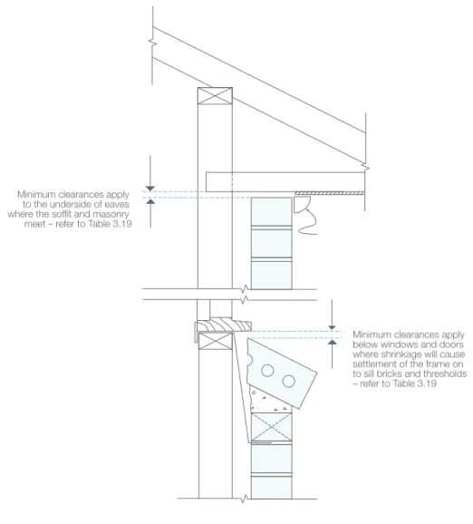
Brick sills, sill tiles and shrinkage allowance for timber framing
Window frames, sill tiles and sill bricks are defective if they are distorted or dislodged. Eaves where the soffit and the masonry meet are defective if they are not installed with the minimum clearances set out in Table 3.19.
Brick sills are defective if they are not laid with a consistent slope to each elevation and adequate slope to provide drainage away from the opening.
Refer also to Diagram 3.19.
3
MASONR
Y
CONTENTS
NEXT CHAPTER
PREVIOUS CHAPTER
TABLE 3.19
SHRINKAGE ALLOWANCE FOR TIMBER FRAMING
Type of frame/
construction Single storeyApproximate total shrinkage (mm)Two storey
Slab to lower floor
Timber to lower floor
Slab to lower floor
Timber to lower floor
Fully seasoned timber frame (bearers, joists and wall frame)
0 0 0 0
Seasoned softwood wall frame,
unseasoned softwood joists, bearers in-line
0 10 10 20
Unseasoned softwood wall frame, seasoned joists and bearers
5 5 11 11
Unseasoned hardwood wall frame, seasoned joists and bearers
9 9 22 22
Unseasoned hardwood wall frame, unseasoned softwood joists, bearers in-line
9 19 32 42
Seasoned softwood frame, unseasoned hardwood bearers and joists
0 22 20 42
Taken from AS 4773.2-2010 – Masonry in small buildings – Construction, Table 9.1: Minimum clearance for timber framing shrinkage. Reproduced with permission from SAI Global Ltd under Licence 1407-c122.
3
MASONR
Y
DIAGRAM 3.19
SHRINKAGE ALLOWANCE FOR TIMBER FRAMING
Minimum clearances apply to the underside of eaves where the soffit and masonry meet – refer to Table 3.19
Minimum clearances apply below windows and doors where shrinkage will cause settlement of the frame on to sill bricks and thresholds – refer to Table 3.19 CONTENTS
NEXT CHAPTER
PREVIOUS CHAPTER
34 VBA | GUIDE TO STANDARDS AND TOLERANCES 2015
4
FRAMING
4 FRAMING
4.01
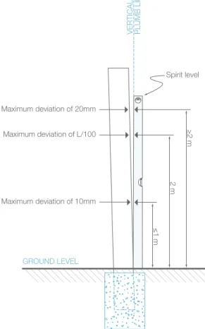
Verticality or plumbness of stumps or piles
Stumps or piles are defective if they deviate from vertical by more than: a) 10 mm for stumps or piles up to 1 m in height
b) L/100 for stumps or piles up to 2 m in height
c) 20 mm for stumps or piles greater than 2 m in height. Refer to Diagram 4.01.
DIAGRAM 4.01
VERTICALITY OR PLUMBNESS OF STUMPS OR PILES
4.02
Verticality or plumbness of steel and timber frames and exposed posts
Posts and wall frames are defective if they deviate from vertical by more than 5 mm over a 1.8 m height. Refer to Diagram E.
4.03
Straightness of steel and timber frame surfaces
Frames are defective if they deviate from plane (horizontal or vertical bow) by more than 4 mm in any 2 m length of wall. Refer to Diagram E.
GROUND LEVEL
Spirit level
Maximum deviation of 20mm
Maximum deviation of 10mm Maximum deviation of L/100
VER
TICAL
PLUMB LINE
≤1 m
2 m
≥2 m
CONTENTS
NEXT CHAPTER
PREVIOUS CHAPTER
4
FRAMING
4.04
Packing under bearers
Packing to stumps or piers under bearers is defective if it is not made of durable, non-compressible materials, such as engineered plastic packers, or does not provide the minimum bearing area required by AS 1684, is more than a total thickness of 20 mm, or is not fixed in a proper and workmanlike manner.
4.05
Timber shrinkage
Timber is defective if it has shrunk more than 10 per cent for unseasoned timber, or three per cent for seasoned timber.
4.06
Treads and risers in timber stairs
Timber stairs are defective if they do not comply with the requirements of the Building Code of Australia.
The finished riser and going dimensions after installation of floor finishes nominated in the contract are defective if they do not result in consistent riser and going dimensions as required by the BCA.
A tolerance of up to 5 mm consistent throughout the flight of the stair from the nominated dimensions in the approved documents is considered acceptable.
This tolerance shall not be applied to allow for poor construction practice.
4.07
Fixing stud walls to concrete slabs
Bottom plates are defective if they are not fixed to concrete slabs in accordance with AS 1684.
Depending on the manufacturer’s requirements for the concrete nail/masonry anchor used and the required uplift pull-out force and wind category, the distance of the fixing from the edge of the slab is required to be between 50 mm and 70 mm for standard 20 MPa concrete. The fixing point cannot be less than five times the diameter of the fastener from the edge of the timber plate which equates to 25 mm for a 5 mm diameter nail and 50 mm for a 10 mm diameter masonry anchor.
CONTENTS
NEXT CHAPTER
PREVIOUS CHAPTER
36 VBA | GUIDE TO STANDARDS AND TOLERANCES 2015
4.08
Bottom plates that overhang concrete slabs
Bottom plates that are less than 90 mm wide and overhang concrete slabs are defective. Bottom plates that are 90 mm wide or greater and overhang concrete slabs by more than 10 mm are defective.
Minimum cavity widths as required by the Building Code of Australia shall be maintained.
DIAGRAM 4.08
BOTTOM PLATES THAT OVERHANG CONCRETE SLABS
Documented width of cavity Fastener’s minimum edge distance from edge of the bottom plate
Fastener’s minimum edge distance from concrete edge requirements
15 mm maximum brick overhang as per BCA 10 mm
maximum bottom plate overhang
Masonry wall skin 90 mm
(min) Stud
Concrete slab
4
FRAMING
CONTENTS
NEXT CHAPTER
PREVIOUS CHAPTER
5
W
ALL CLADDING
5
WALL CLADDING
5.01
Leaks in wall cladding
Completed wall cladding and accessories are defective if they leak under normal weather conditions and are due to the builder’s workmanship, cause unhealthy or dangerous conditions, loss of amenity for occupants, undue dampness or deterioration of building elements.
5.02
Wall cladding
Staining, folds, splits, dents, open joints between panels, cracking and other distortions in wall cladding are defective if they are visible from a normal viewing position at ground level or an upper floor level.
Any unintended corrosion of metal wall cladding is defective unless it is due to lack of maintenance by the owner.
CONTENTS
NEXT CHAPTER
PREVIOUS CHAPTER
38 VBA | GUIDE TO STANDARDS AND TOLERANCES 2015
6
ROOFING
6 ROOFING
6.01
Leaks in roofing, flashings and accessories
Roofing, including flashings and accessories, is defective if it leaks under normal weather conditions and is due to the builder’s workmanship, causes unhealthy or dangerous conditions, loss of amenity for occupants, undue dampness or deterioration of building elements.
6.02
Roof cladding
Staining, folds, splits, dents, open joints between panels, cracking and other distortions in roof cladding is defective if it is visible from a normal viewing position at ground level or an upper floor level.
Any corrosion of roof cladding is defective unless it is caused by a lack of maintenance or damaged by the owner.
6.03
Roof tiles
Roof tiles are defective if they do not conform to the manufacturer’s sample. Irregularities in tiles are defects if they are visible from a normal viewing position at ground or upper floor levels.
Minor surface marks or blemishes arising from the tile manufacturing process are not defective.
Cracked or broken roof tiles are defective if caused by the builder’s workmanship.
6.04
Roof tile pointing
Unless documented otherwise, the absence of pointing where required is defective.
Pointing is defective if it becomes dislodged or washed out.
The pointing is defective if it is not uniform in colour, texture and trowelled off to provide a neat appearance. The rectification of pointing shall match the existing colour and texture as close as practicable.
Minor cracking of pointing is not defective.
CONTENTS
NEXT CHAPTER
PREVIOUS CHAPTER
6
ROOFING
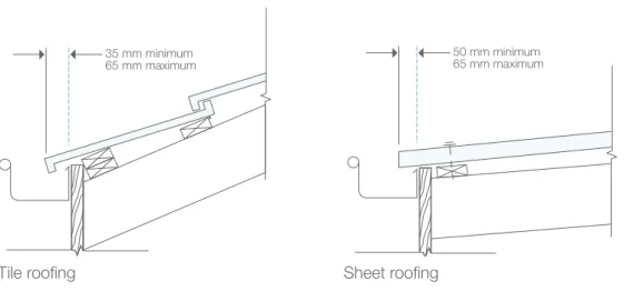
6.05
Overhang of roofing (tiles and sheet roofing)
Tiled roofing is defective if tiles overhang the inside face of a gutter by less than 35 mm or by more than 65 mm.
Sheet roofing is defective if it overhangs the inside face of a gutter by less than 50 mm or by more than 65 mm.
DIAGRAM 6.05
OVERHANG FOR ROOFING
35 mm minimum
65 mm maximum 50 mm minimum65 mm maximum
Tile roofing Sheet roofing
6.06
Cutting of roof tiles
Tiles are defective if they are not cut neatly to present a straight line at ridges, hips, verges and valleys.
6.07
Dry valley construction
Dry valleys, where they are documented, are defective if they are not constructed in accordance with the Building Code of Australia or any relevant instructions from roofing tile associations or the manufacturer’s installation instructions.
6.08
Undulating tiled roof lines
Undulations in the line of roof tiles are defective if the variation exceeds 20 mm in any 4 m length measured in the roof plane.
CONTENTS
NEXT CHAPTER
PREVIOUS CHAPTER
40 VBA | GUIDE TO STANDARDS AND TOLERANCES 2015
6.09
Alignment of trusses
Trusses or chords of trusses that bow more than the lesser of L/200 or 50 mm are defective; where L is the length of the truss or chord.
DIAGRAM 6.09
ALIGNMENT OF TRUSSES
Height of any section
Truss
Spirit level
50 mm maximum deviation overall
VER
TICAL
PLUMB LINE
6.10
Verticality or plumbness of trusses
Trusses or parts of trusses that are erected with a vertical deviation more than the lesser of H/50 or 50 mm are defective, where H is the height of the truss.
DIAGRAM 6.10
VERTICALITY OR PLUMBNESS OF TRUSSES
TrussTruss
Bow
Length of truss
Length of truss Bow
6
ROOFING
CONTENTS
NEXT CHAPTER
PREVIOUS CHAPTER