SYNTHESIS AND CHARACTERIZATION OF
N-[3-(DIMETHYL-AMINO)PROPYL]METHACRYLAMIDE/(NANO-SiO
2,
AMINE-MODIFIED NANO-SiO
2AND EXPANDED PERLITE)
NANOCOMPOSITE HYDROGELS
Fatma Özge Gökmen
[a,b]*and Nursel Pekel Bayramgil
[a]Keywords: Nanocomposite hydrogels, nano-SiO2, biocompatibility, SEM-mapping, N-[3-(dimethylamino)propyl]methacrylamide
(DMAPMAAm).
The nanocomposite hydrogel of N-[3-(dimethylamino)propyl]methacrylamide (DMAPMAAm) with different SiO2 particles were prepared
by free radical polymerization. The nano-SiO2 as reinforcement material was used in original, hydrophilic and perlite forms. The swelling
values of nanocomposite hydrogels containing amine-modified nano-SiO2 were found to be higher than those of the original DMAPMAAm
hydrogel and the nanocomposite hydrogel containing original SiO2. SEM and mapping studies with SEM proved the presence of nano-SiO2
particles incorporated into the hydrogel structure.
* Corresponding Authors Fax: +902282141427
E-Mail: [email protected]
[a] Hacettepe University, Chemistry Department, Ankara, Turkey
[b] Bilecik Şeyh Edebali University, Central Research Laboratory, Bilecik, Turkey
INTRODUCTION
Hydrogels are three dimensional hydrophilic polymer networks capable of swelling in water or biological fluids, and retaining a large amount of fluids in the swollen state.1-4
Their ability to absorb water is due to the presence of
hydrophilic groups such as –OH, –CONH–, –CONH2, – COOH, and –SO3H.5 The water content in the
hydrogels affects different properties like permeability, mechanical properties, surface properties, and biocompatibility. Hydrogels have physical properties similar to that of living tissue, and this similarity is due to the high water content, soft and rubbery consistency, and low interfacial tension with water or biological fluids.6-8
Several techniques have been reported for the synthesis of hydrogels. The first approach involves copolymer-rization/crosslinking of co-monomers using multifunctional co-monomer, which acts as crosslinking agent. The polymerization reaction is initiated by chemically. The polymerization reaction can be carried out in bulk, in solution, or in suspension. The second method involves crosslinking of linear polymers by irradiation, or by chemical compounds.9-12
The monomers used in the preparation of the ionic polymer network contain an ionizable group, a group that can be ionized, or a group that can undergo a substitution reaction after the polymerization is completed. As a result, hydrogels synthesized contain weakly acidic groups like carboxylic acids, or a weakly basic group like substituted amines, or a strong acidic and basic group like sulfonic acids, and quaternary ammonium compounds. Some of the
commonly used crosslinking agents include N,N’-methylenebisacrylamide, divinyl benzene, and ethylene glycol dimethacrylate. For co-polymerization/crosslinking reactions in solution, ionic or neutral monomers are mixed with the multifunctional crosslinking agent. The polymerization is initiated by UV, by redox initiator system or thermally. The presence of solvent serves as heat sink, and minimizes temperature control problems. The prepared hydrogels need to be washed with distilled water to remove the unreacted monomers, crosslinking agent, and the initiator.13,14
In this study, N-[3-(dimethylamino)propyl]methacryl-amide (DMAPMAAm) was used as a monomer. Nano-SiO2
was added to the solution of DMAPMAAm with the crosslinking agent and initiator and crosslinked disk shaped nanocomposite hydrogels were obtained. The nano-SiO2
used as reinforcement material is in both original and hydrophilic forms (amine-modified) and were commercially purchased. In the preparation of nanocomposite hydrogels, DMAPMAAm monomer was preferred because of its biocompatibility feature.
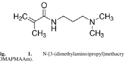
Fig. 1. N-[3-(dimethylamino)propyl]methacrylamide
(DMAPMAAm).
All of the selected materials have been chosen in consideration of the fact that they are harmless to the environment and can work in harmony with the human body. After the behavior of nano-SiO2 in hydrogels was
determined, the volcanic rock type Perlite, which is common in nature and cheaper than the commercial cost of nano-SiO2,
Table 1. Percent swelling (S %) values of nanocomposite hydrogels.
Conversion, % (C) : 100*(m1/m0); Crosslink % (CL, gelation %) = 100 *(m2/m1ı); Swelling degree (S %) =100*[mt-m2)]/m2; [Monomer +
Crosslinker + Initiator+(nanoparticles)] = m0; Mass of dry hydrogel = m1; Mass of 3 or 4 pieces of dry hydrogel = m1ı; Mass of 3 or 4
pieces of hydrogel after washing and drying = m2; Mass of swollen hydrogel at time “t” = mt.
The perlite design of the polymer/clay nanocomposite is due to the fact that its high SiO2 content (~75 %) and the
purity is rather high compared to other clays. This allowed us observe the behaviour of SiO2 in perlite form and
compare the results with those of pure nano-SiO2 in the
nanocomposite hydrogel structure.
EXPERIMENTAL
Neutral nano-SiO2 (15-20 nm, 99.5 %, Skys
nanomaterials), hydrophilic nano-SiO2 with amine groups
via long alkyl chains (10-20 nm, 99.8%, Skys nanomaterials), expanded perlite (EP) (ETİ Mine Operations), DMAPMAAm (Sigma-Aldrich), N,N’-methylenebisacrylamide (N,N’-MBAAm) (Sigma-Aldrich) and azobisisobutyronitrile (AIBN) (Merck) were used as supplied.
Preparation of hydrogels
The crosslinked cylindrical hydrogels were prepared by using DMAPMAAm monomer in PVC straws. The hydrogel solution containing monomer, initiator, crosslinking agent, solvent, and nanoparticles was heated in a temperature-controlled water bath (at 80 °C) for 2 h. Then, the PVC straws were carefully removed from bath, cut into cylindrical discs (3-4 mm in length) with a knife, and the hydrogels were dried in air before kept in vacuum oven (35 °C).
Swelling properties
Percent swelling (S %) values of nanocomposite hydrogels were calculated using the following equations, where m0 is
the initial mass of dry hydrogel, mt is the mass of swollen
hydrogel at time t. When the equilibrium state is reached, the swollen hydrogel has the greatest swelling value.
Measurements
FT-IR analyzes were performed on a Perkin Elmer Spectrum 100 model FT-IR. The wave number range is 400-4000 cm-1. ATR mode was used and each spectrum was
scanned 4 times and worked at a resolution of 4 cm-1. SEM
analyzes were performed with Carl Zeiss Supra 40VP model SEM device. The surfaces are plated with Qourum brand coating device to ensure conductivity with platinum in the hydrogels. While the surfaces were being photographed, SE
(secondary detector) was used. Inorganic particle distributions in nanocomposite hydrogels were determined by applying the mapping method with the Bruker EDX detector. TGA analyzes were performed with the SETARAM simultaneous TG / DTA instrument. The heating was carried out at a temperature range of 25 °C-900 °C with a heating rate of 10 °C min-1 in N
2 atmosphere.
For better examination of the pore structures of the nanocomposite hydrogels, the water adsorbed hydrogels were put in a freezer (kept at -18 °C) for 12 h, then placed in a vacuum device with frozen states (instrument: Labconco, Freezone 2.5 (Canada) lyophilizer). Hydrogels that have been pressurized in the apparatus for 16 h were examined in FESEM without deformation by the water separation inside.
RESULTS AND DISCUSSION
Surface morphologies of original i.e. neutral nano-SiO2
and amine-modified (hydrophilic, hf) nano-SiO2 used in this
study were shown in Fig. 2. As seen from these figures, while the surface of nano-SiO2 is rough and irregular, the
surface of amine-modified nano-SiO2 is more regular and
presents more uniform particle size distribution.
Figure 2. SEM photographs of (A) amine-modified nano-SiO2 and
(B) nano-SiO2.
The results for gravimetric determination of nanocomposite hydrogels were given as table in the experimental section. From Table 1, it is apparent that nanocomposite hydrogels having amine-modified nano-SiO2
showed more swelling than plain DMAPMAAm hydrogel and neutral nano-SiO2 doped nanocomposite hydrogel.
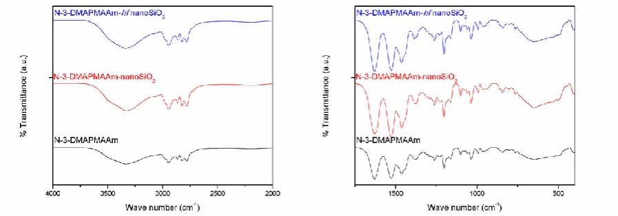
Structural changes observed for nanocomposite hydrogels were evaluated taking into account FT-IR results, shown in Fig. 3. The bands appearing on the spectrum are as follows: bands between 2650 cm-1 and 2950 cm-1 belong to CH
2 and
CH groups of DMAPMAAm, respectively. The band for C = O groups of DMAPMAAm was seen at 1620 cm-1.15
DMAPMAAm
Plain Neutral nano-SiO2 doped Amine-modified nano-SiO2 doped Expanded perlite doped
C, %
%
CL % S % C % CL % S % C % CL % S % C % CL % S %
Figure 3. FT-IR spectra of DMAPMAAm, DMAPMAAm nano-SiO2 and DMAPMAAm –hydrophilic (hf) nano-SiO2.
The bands at 900-1550 cm-1 indicate C-H bending in
DMAPMAAm structure. Structural changes in nanocomposite hydrogels are much more difficult to understand then plain hydrogels because the nano-SiO2
contribution is very small.
Figure 4. FT-IR spectra of DMAPMAAm, EP and DMAPMAAm
EP.
Figure 4 shows the FT-IR spectrum of DMAPMAAm and EP doped DMAPMAAm nanocomposite hydrogel. In the spectrum, the H-bonding interactions between EP and the hydrogen in the Si-OH groups of nanocomposite hydrogel were also observed. The sharp band observed at 480 cm-1 attributed to the Si-O-Si vibrations of EP was not
observed in the nanocomposite spectrum because the amount of EP entering the DMAPMAAm was very low.
Surface morphologies of nanocomposite hydrogels were investigated by using SEM instrument by the aid of lyophilizer and mapping method. SEM photographs were taken by applying three methods. Following three Fig. s were about these evaluations. When classical SEM analysis of the nanocomposite hydrogels was performed, the cross-section was first taken as it is from the dried hydrogels and then the surface photographs were recorded. The SEM images given in Fig. 5 did not clarify the morphological structure of the nanocomposite, only showed how the nanoparticles influence the hydrogel structure.
Figure 5 shows the 500-magnified SEM images for DMAPMAAm hydrogels (A), with nano-SiO2 added (B),
amine-modified nano-SiO2 added (C), and EP added (D)
forms.
Figure 5. SEM images: (A) DMAPMAAm hydrogel; DMAPMAAm nanocomposite hydrogels having (B) nano-SiO2,
(C) (hf) nano-SiO2, and (D) EP.
Figure 6. SEM images of lyophilized (A) DMAPMAAm hydrogel and (B) DMAPMAAm /nano-SiO2, (C) DMAPMAAm
/amine-modified hydrophilic nano-SiO2, and (D) DMAPMAAm /EP
While nano-SiO2 doped DMAPMAAm nanocomposite
hydrogels (B) have a rough structure, surface roughness of EP doped DMAPMAAm nanocomposite hydrogels (D) has increased. Amine-modified hydrophilic nano-SiO2-added
hydrogel (C) showed exact conformity to the original hydrogel structure caused a decrease in surface roughness
Figure 7. Mapped SEM images of (A) DMAPMAAm hydrogel and (B) DMAPMAAm/nano-SiO2, (C)
DMAPMAAm/amine-modified nano-SiO2, (D) DMAPMAAm/EP nanocomposite
hydrogels.
Second, the nanocomposite hydrogels were brought to swollen state and lyophilization were applied followed by taking SEM photographs. SEM photographs of lyophilized specimens showed pore and mesh structures. Finally, EDX spectra were taken to prove that the hydrogels were doped with nano-SiO2, amine-modified nano-SiO2 and EP. In
literature, the elemental maps of nanocomposites have been identified by EDX and distributions of doped nanoparticles has been proven.16
Fig. 6A shows the SEM image for lyophilized pure DMAPMAAm hydrogel; the average pore diameters were recorded as 4,147 μm. The pores have an uniform
distribution. In Fig. 6B, the diameters of pores in nano-SiO2
doped DMAPMAAm nanocomposite hydrogel increased from 4.147 μm to 5.845 μm. The pore distribution is still homogenous. This image also shows the wall thickness of the nanocomposite increased after the addition of dopant nanoparticles. Fig. 6C shows the surface structure of DMAPMAAm nanocomposite hydrogel with amine-modified hydrophilic nano-SiO2. The pores are arranged in a
different manner. In Fig. 6D, the average pore diameter of the DMAPMAAm nanocomposite hydrogel with EP was 5.621 μm and homogeneous distribution was observed.
Fig. 7B shows a mapped SEM image giving elemental distribution of nano-SiO2 doped DMAPMAAm. In the
hydrogel structure, the elements are much more prominent in the pores than on the walls (It was shown Fig. 7C and D clearly). It is possible to see Si and O elements in the same frequency and homogeneously in the walls as the pores are filled with hydrophilic nano-SiO2, because its surface
compatibility is higher than the other additives (neutral SiO2
and EP) in the mapping method. The element distribution of hydrophilic nano-SiO2 doped DMAPMAAm hydrogels was
clearly observed in Fig. 7C. In the mapping studies (Fig. 7D) made to indicate the element distribution of the EP-doped DMAPMAAm nanocomposite hydrogel, the distribution of Si, O, Al, Mg and K elements in the perlite was shown to be homogenous in the pores.
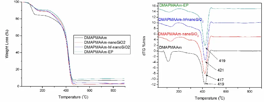
In addition to the structural and morphological characterization, the nanocomposite hydrogel has also been examined for thermal stability. In a TGA curve, which is a study of the formation of copolymers on polypropylene films with DMAPMAAm, 50% parts of DMAPMAAm is reported to degrade at 406 °C.17 In Fig. 8 (B), the maximum
decomposition temperature of DMAPMAAm hydrogel is 419 °C. And weight loss was calculated ~ %80. From the doped composites it has been found that the amine-modified nano-SiO2, which has been proven to be fully compatible
with the structure, has a maximum breakdown temperature of 421 °C. Thermal decomposition of nanocomposite hydrogels has been start at 200 °C and has completed at 470 °C.
CONCLUSION
The experimental conditions for all nanocomposite hydrogels were determined in the same way during the synthesis of the study. After the behavior of nano-SiO2 in
hydrogels was determined, the volcanic rock type Perlite, which is common in nature and cheaper than the commercial cost of nano-SiO2, is doped to DMAPMAAm hydrogels.
The perlite design of the polymer / clay nanocomposite is due to the fact that its high SiO2 content (~75%). This
allowed us to be informed about the behavior of SiO2 in
perlite from the results obtained by observing the pure nano-SiO2 behavior of the nanocomposite hydrogel structure.
Structural and morphological characterization were performed by FT-IR, and detailed SEM analyses. The results showed that the amine-modified nano-SiO2 was in
complete conformity with the DMAPMAAm hydrogels, resulting in improved swelling, mechanical, morphological and thermal properties.
The behaviour of three different SiO2 reinforcements in
composite hydrogels during the planning of target-focused work with SiO2 doped nanocomposite hydrogels is
important in interpreting the results to be achieved in the target applications.
ACKNOWLEDGMENT
We are grateful to Bilecik Seyh Edebali University Central Research Laboratory for providing FT-IR, FESEM and TGA measurements.
REFERENCES
1Bouwstra, J. A., Jungiger, H. E., In: Swarbrick, J. and Boylan, J.
C., Eds., Encyclopedia of Pharmaceutical Technology, 1st Edition, Vol. 7, Marcel Dekker Inc, New York, 1993.
2Gaharwar, A. K., Peppas, N. A., Khademhosseini, A., Biotechnol.
Bioeng., 2014, 111, 441-453. DOI: 10.1002/bit.25160
3Paul, D. R., Robeson, L. M., Polymer, 2008, 49, 3187-3204.
https://doi.org/10.1016/j.polymer.2008.04.017
4Shetye, S. P., Godbole, A., Bhilegaokar, S., Gajare, P., IJSRM.
Human, 2015, 1(1) , 47-71.
5Satish, C. S., Satish, K. P. and Shivakumar, H. G., Indian J.
Pharm. Sci., 2006, 68 (2), 133-140. DOI: 10.4103/0250-474X.25706
6Blanco, M. D., Garcia, O., Trigo, R. M., Teijon, J. M. and Katime,
I., Biomaterials, 1996, 17 (11), 1061-1067.
https://doi.org/10.1016/0142-9612(96)85906-0
7Ahmed, E. M., J. Adv. Res., 2015, 6 (2), 105-121.
https://doi.org/10.1016/j.jare.2013.07.006
8Hamidi, M., Azadi, A., Rafiei, P., Adv. Drug Del. Rev., 2009, 60
(15), 1638–1649. https://doi.org/10.1016/j.addr.2008.08.002
9Peppas, N. A. and Khare, A. R., Adv. Drug Del. Rev.,1993, 11
(1-2), 1. https://doi.org/10.1016/0169-409X(93)90025-Y
10Anisha, S., Kumar, S. P., Kumar, G. V., Garima, G., Int. J.
Pharm. Sci. Rev. Res., 2010, 4 (2),102.
11Sun, X., Zhang, G., Shi, Q., Tang, B., Wu, Z. J., J. Appl. Polym.
Sci., 2002, 86, 3212–3717.
12Kashyap, N., Kumar, N., Kumar, M., Critical Crit. Rev. Ther.
Drug, 2005, 22(2), 107–149. DOI: 10.1615/CritRevTherDrugCarrierSyst.v22.i2.10
13Ulusoy, U., Şimşek, S., J. Hazard. Mater., 2005, 127 (1), 163–
171. https://doi.org/10.1016/j.jhazmat.2005.06.036
14Malhotra, S. L., Parikh, K. K., Blumstein, A., J. Colloid Interf.
Sci., 1972, 41 (2), 318-327. https://doi.org/10.1016/0021-9797(72)90117-8
15Chen, J., Yang, L., Nho, Y. C., Hoffman, S., Topics in Tissue
Engineering, 4, Chapter 14, 2008. 16Ganeshraja, A. S., Clara,
A. S., Rajkumar, K., Wang, Y., Wang, J., Anbalagan, K., Appl. Surf. Sci., 2015, 353, 553-563.
https://doi.org/10.1016/j.apsusc.2015.06.118
17Contreras-Garcia, A., Alvarez-Lorenzo, C., Concheiro, A., Bucio,
E., Radiat. Phys. Chem., 2010, 79 (5), 615-621.
https://doi.org/10.1016/j.radphyschem.2009.12.007