Automated Drone Calibration System
Final Design Review
Inspired Flight Calibration Team [email protected]
Jackie Paik Matthew Carlson
Zach Richter Tyler Van Den Berg
Ryan Zhan
Mechanical Engineering Department
Statement of Disclaimer
i Abstract
The final design review of the Inspired Flight Calibration Team senior project will detail the process used to complete a verification prototype of a drone calibration device and discuss lessons learned and suggestions for improving this device. Going from brainstorming and conceptual prototyping all the way through verification prototyping and testing, we were able to design a gyroscopic device that met
Table of Contents
Abstract ... i
1.0 Introduction ... 1
2.0 Background ... 1
2.1 Summary of the Meeting with Inspired Flight... 1
2.2 Current Process ... 2
2.3 Drone Regulations... 2
2.4 Research Tables ... 2
3.0 Objectives... 6
3.2 Boundary Diagram ... 6
3.3 Specifications ... 7
3.4 High-risk Items ... 8
4.0 Concept Design ... 8
4.1 Brainstorming... 8
4.2 Concept Models ... 9
4.3 Decision Matrices ... 10
4.4 The Decision and What Follows ... 12
4.4.1 Mechanical Design... 12
4.4.2 Electronic Hardware Design ... 15
4.4.3 High Level Software Design... 15
4.5 Preliminary Analysis... 16
4.6 Design Hazards and Unknowns ... 17
5.0 Final Design ... 17
5.1 Mechanical Design Model and Diagrams ... 17
5.1.1 Original Structural Design Goals ... 17
5.2 Final Electrical Design... 24
5.2.1 Original Electrical Design Goals ... 24
5.2.2 Final Electrical Result ... 24
5.3 Final Software Design... 24
5.3.1 Original Arduino Software Design Goals ... 25
5.3.2 Arduino Software Results ... 26
5.3.3 Original Master Mind Design Goals ... 27
5.3.4 Master Mind Results and Organization ... 27
5.4 Preliminary and Design Tool Calculations ... 28
5.5 Safety and Maintenance ... 29
iii
6.0 Manufacturing ... 30
6.1 Procurement ... 30
6.2 Manufacturing Instructions ... 30
6.3 Assembly... 34
6.4 Discussion of Lessons Learned and Recommendations ... 36
7.0 Design Verification ... 37
7.1 Engineering Specifications ... 37
7.2 Verifying Specifications ... 37
8.0 Project Management ... 38
8.1 Overall Design Process ... 39
8.2 Unique Prototyping/Testing Techniques for Project... 40
8.3 Next Steps ... 40
8.4 Project Management Reflections ... 40
9.0 Conclusions and Recommendations ... 41
9.1 Reflection ... 41
9.2 Issues and Recommended Fixes ... 42
9.3 Looking Forward... 43
Works Cited ... 45
List of Figures
Figure 1. Boundary Diagram Demonstrating Our Scope ... 6
Figure 2. Functional Decomposition... 9
Figure 3. Concept models generated through ideation process ... 10
Figure 4. Concept prototype for the gyroscopic design, laser cut from MDF ... 13
Figure 5. Concept prototype for turntable arm, laser cut from MDF ... 14
Figure 6. Isometric concept CAD model of gyroscope device ... 15
Figure 7. Diagram of General Organization of Calibration ... 16
Figure 8. Mockup of Structural Prototype Design ... 18
Figure 9. Overall View of Structural Prototype ... 19
Figure 10. Inner Ring Subsystem on Structural Prototype ... 19
Figure 11. Outer Fork Subsystem on Structural Prototype ... 20
Figure 12. Detail View of the Secondary Axis Joint ... 20
Figure 13. Rendering of Final Design... 21
Figure 14. Close-up of Driver Mount Assembly ... 22
Figure 15. Close-up of Proximity Sensors ... 22
Figure 16. Close-up of Primary Motor Torque Conversion ... 23
Figure 17. Communication Diagram of Three Main Computers ... 24
Figure 18. Original Arduino State Diagram ... 25
Figure 19. Final Arduino State Diagram... 26
Figure 20. Original Master Mind State Diagram ... 27
v List of Tables
Table 1. Patent Research Summary ... 3
Table 2. Similar Product Research Summary ... 4
Table 3. Journal Articles Research Summary ... 5
Table 4. Engineering Specification Table... 7
Table 5. Morph Chart ... 10
Table 6. Top Concept Designs ... 11
Table 7. Decision Matrix ... 12
Table 8. List of expected program tasks and their functions ... 16
Table 9. Custom Manufactured Parts... 31
Table 10. 8020 Cut Lengths for Verification Prototype ... 34
Table 11. Modified Specification Table with Results ... 38
Table 12. Key Project Deliverables/Dates ... 40
1.0 Introduction
This senior project was brought to California Polytechnic State University by Inspired Flight, a
commercial drone manufacturer and distributer. Inspired Flight hopes to have a new calibration and test process for their drones. Currently, each drone is manually calibrated and run through a flight test before being shipped, which sometimes leads to inaccuracies in the flight controller system. The company is looking to automate this process to achieve more consistency as well as reduce the employee hours needed from their engineers to complete this task. Our team consists of five mechanical engineering students, Jackie Paik, Matthew Carlson, Ryan Zhan, Tyler Van Den Berg, and Zach Richter. Our interests and skills vary from robotics and mechatronics to mechanical design and manufacturing. This report will describe in detail the entire process from research and setting objectives that led us to a preliminary design, and how the analysis of our design created improvements and allowed us to select specific components and plan the manufacturing process and software structure. This design is
elaborated on in detail within the Final Design, Manufacturing Plan, and Design Verification Plan sections. Potential risks and challenges are also examined, and a project timeline is presented in the Project Management section.
2.0 Background
The objectives were determined by interviewing the Inspired Flight engineers and conducting research. From this, we gained a deeper understanding of the problems with the current calibration process and learned from technical research on different sensors and their calibration methods. The information gathered from the research is described in the Background section of this report. It contains what we learned about the company’s needs and wants as well as relevant information on topics that are
important for understanding areas of technology and engineering that will be prevalent in this project.
2.1 Summary of the Meeting with Inspired Flight
During the first meeting with our sponsors from Inspired Flight, Marc Stollmeyer and Martin Bialy, they discussed the expectations they had for the scope of this project. This conversation serves as background for the research conducted. The project is to be twofold: the primary goal being to do the calibration of the flight systems and the secondary being to run the drone through a simulated flight test. The first goal would ideally be for us to build a system that can autonomously and accurately run a drone through a six-orientation flight controller calibration, a “level horizon” calibration, and an on-board compass calibration. An optional second goal would involve holding the drone in place while feeding preset signals to the motors and using sensors to verify proper drone operation (Stollmeyer). Due to lack of time and resources, we were unable to work on this optional second goal.
The current calibration is done by hand and is not very precise, having an exact process that can be autonomously carried out would save Inspired Flight time and money, and ensure that their drones can be shipped out more quickly. Currently 1 in 4 drones have internal sensor issue out of the box and 1 in 5 drones need recalibration after their first test flight. The current flight tests are all done manually,
2 2.2 Current Process
In order to design a product to assist in Inspired Flight’s drone calibration process, we learned about their current process. At the Inspired Flight facility, we observed a drone calibration and what each of the steps involved. An important component in the process is the calibration software, QGroundControl. This contains the entire user interface for flying and calibrating the drones. The software is entirely open-sourced, and we researched the user guide and calibration documentation for the program (Gagne). During the observation, we saw the different requirements for each type of sensor to be calibrated. The various steps, drone orientations, and possible errors for the calibration processes are detailed below. Errors stemming from inaccurate calibration have the potential to cause decreased stability or constant drift which negatively affect the performance of the drone. All these calibration motions, positions, and errors will be considered when choosing designs to prototype. The exact step-by-step calibration and possible errors due to poor calibration are found in Appendix A.
2.3 Drone Regulations
When researching about drone calibration regulations, we were surprised to find very few standards relating to the actual calibration process. As aircrafts, UAV regulations are primarily set by the FAA. What we did find was primarily about required drone licensing for various sizes and classifications, as well as pilot licenses and restricted flight areas. This includes a ban for flying unmanned aircrafts on the Cal Poly campus without Cal Poly UAS approval (“Unmanned Aircraft Systems”). The only
information we found about preflight calibration was “Conduct a preflight inspection, to include specific aircraft and control station systems checks, to ensure the small Unmanned Aerial System (UAS) is in a condition for safe operation” (United States, Congress). This statement is vague considering the preflight calibration process varies based on the drone and flight controller in use. Due to the lack of specific calibration requirements, government regulations are not currently a significant factor. 2.4 Research Tables
Table 1. Patent Research Summary
Patent Summary How this is helpful Image
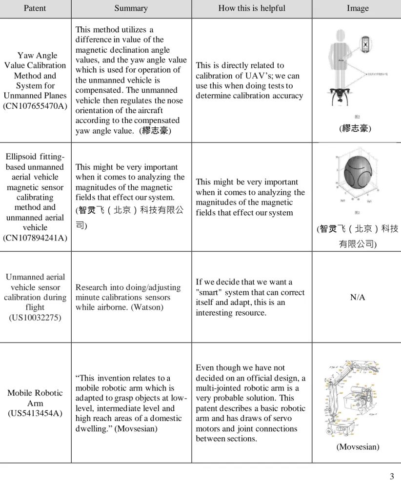
Yaw Angle Value Calibration Method and System for Unmanned Planes (CN107655470A)
This method utilizes a difference in value of the magnetic declination angle values, and the yaw angle value which is used for operation of the unmanned vehicle is compensated. The unmanned vehicle then regulates the nose orientation of the aircraft according to the compensated yaw angle value. (繆志豪)
This is directly related to calibration of UAV’s; we can use this when doing tests to determine calibration accuracy
(繆志豪)
Ellipsoid fitting-based unmanned
aerial vehicle magnetic sensor calibrating method and unmanned aerial vehicle (CN107894241A)
This might be very important when it comes to analyzing the magnitudes of the magnetic fields that effect our system.
(智灵飞(北京)科技有限公
司)
This might be very important when it comes to analyzing the magnitudes of the magnetic fields that effect our system
(智灵飞(北京)科技
有限公司)
Unmanned aerial vehicle sensor calibration during
flight (US10032275)
Research into doing/adjusting minute calibrations sensors while airborne. (Watson)
If we decide that we want a "smart" system that can correct itself and adapt, this is an interesting resource.
N/A
Mobile Robotic Arm (US5413454A)
“This invention relates to a mobile robotic arm which is adapted to grasp objects at low-level, intermediate level and high reach areas of a domestic dwelling.” (Movsesian)
Even though we have not decided on an official design, a multi-jointed robotic arm is a very probable solution. This patent describes a basic robotic arm and has draws of servo motors and joint connections between sections.
4 Table 2 describes the research results of similar products within the scope of the project. It can be seen in the table that not much exists for this particular process.
Table 2. Similar Product Research Summary
Product Summary How this is helpful Image
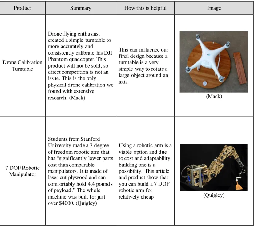
Drone Calibration Turntable
Drone flying enthusiast created a simple turntable to more accurately and
consistently calibrate his DJI Phantom quadcopter. This product will not be sold, so direct competition is not an issue. This is the only
physical drone calibration we found with extensive
research. (Mack)
This can influence our final design because a turntable is a very simple way to rotate a large object around an axis.
(Mack)
7 DOF Robotic Manipulator
Students from Stanford University made a 7 degree of freedom robotic arm that has “significantly lower parts cost than comparable
manipulators. It is made of laser cut plywood and can comfortably hold 4.4 pounds of payload.” The whole machine was built for just over $4000. (Quigley)
Using a robotic arm is a viable option and due to cost and adaptability building one is a possibility. This article and product show that you can build a 7 DOF robotic arm for
5 Table 3 outlines the research conducted of journal articles relevant to the project and provides insight into said relevance.
Table 3. Journal Articles Research Summary
Journal Articles Summary How this is helpful Image
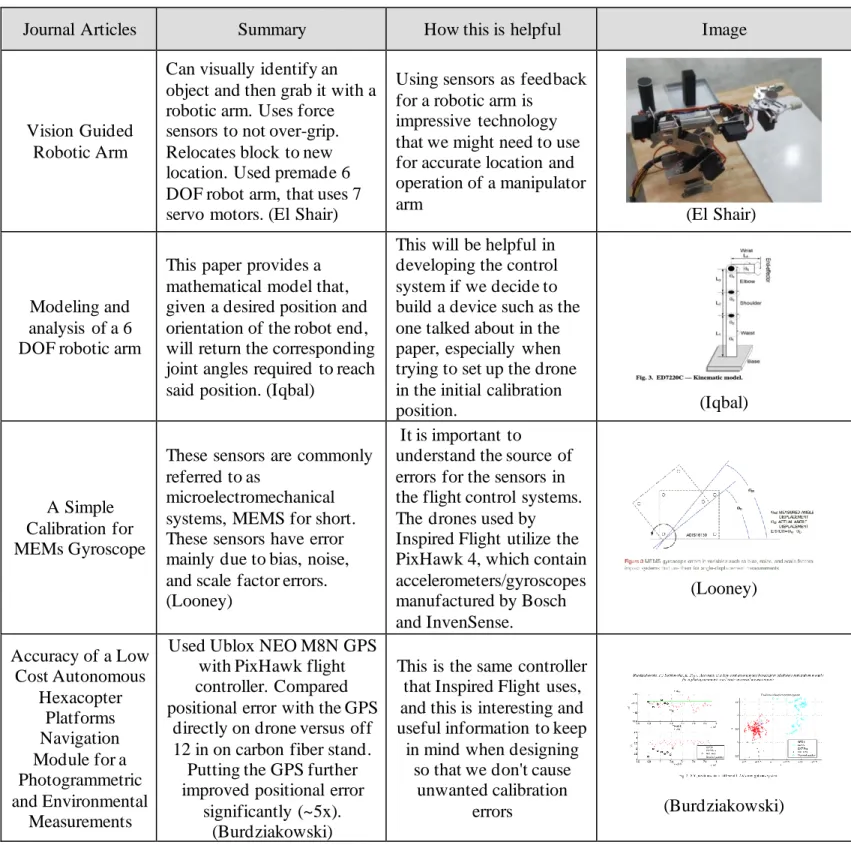
Vision Guided Robotic Arm
Can visually identify an object and then grab it with a robotic arm. Uses force sensors to not over-grip. Relocates block to new location. Used premade 6 DOF robot arm, that uses 7 servo motors. (El Shair)
Using sensors as feedback for a robotic arm is
impressive technology that we might need to use for accurate location and operation of a manipulator arm
(El Shair)
Modeling and analysis of a 6 DOF robotic arm
This paper provides a mathematical model that, given a desired position and orientation of the robot end, will return the corresponding joint angles required to reach said position. (Iqbal)
This will be helpful in developing the control system if we decide to build a device such as the one talked about in the paper, especially when trying to set up the drone in the initial calibration
position. (Iqbal)
A Simple Calibration for MEMs Gyroscope
These sensors are commonly referred to as
microelectromechanical systems, MEMS for short. These sensors have error mainly due to bias, noise, and scale factor errors. (Looney)
It is important to
understand the source of errors for the sensors in the flight control systems. The drones used by Inspired Flight utilize the PixHawk 4, which contain accelerometers/gyroscopes manufactured by Bosch and InvenSense.
(Looney)
Accuracy of a Low Cost Autonomous
Hexacopter Platforms Navigation Module for a Photogrammetric and Environmental
Measurements
Used Ublox NEO M8N GPS with PixHawk flight controller. Compared positional error with the GPS
directly on drone versus off 12 in on carbon fiber stand.
Putting the GPS further improved positional error
significantly (~5x). (Burdziakowski)
This is the same controller that Inspired Flight uses, and this is interesting and useful information to keep in mind when designing
so that we don't cause unwanted calibration
6 3.0 Objectives
The Objectives section will define what is included in the scope of this project. Outlining the major goals for this project is important for ensuring that the final design solves the problem that Inspired Flight has with their current calibration and test process. The scope also ensures that the tasks that our team has determined are accomplishable within the year long duration of this project. From the QFD we see that the most important quality of the device is the ability to reliably and accurately calibrate the drone. A Quality Function Deployment (QFD) is included as an attachment to demonstrate how the engineering specifications were chosen from the customer’s needs and wants.
3.1 Problem Statement
Inspired Flight Technologies would like a way to calibrate then test the calibration of their unmanned aircrafts with a more consistent procedure, as the current processes are conducted manually; this can be slow, awkward, and a potential source of error.
3.2 Boundary Diagram
Figure 1 shows the scope of our work in a graphical manner. The system which we are to design is enclosed in the dotted line. Factors that will affect our design, but which are not in our control, are included on the boundary of our system. An example of this is the roof/metal objects that we will not change but will need to be aware of in order to avoid magnetic interference during calibration.
7 3.3 Specifications
To determine the specifications, we recorded the needs of Inspired Flight that the device must meet. These needs include the ability to fit through a doorway, be easily transportable, withstand the outdoors to some degree, be simple to use, and to be compatible with Inspired Flight’s current and future drones (Stollmeyer). Other lower priority “wants” were also defined for the project. These needs were put into a Quality Function Deployment (QFD) and compared against more quantifiable specifications well as current alternatives to find the most important specifications. During the writing of the QFD, we ensured that all needs were accommodated for that there was no over-specification of the problem. Once
completed, the priorities of the engineering specifications were determined . A completed QFD can be found in Appendix B and the entire list of specifications required of the device can be seen in Table 4. This table has been updated to reflect more relevant compliance ratings, as many of the simple
measurements better characterized as inspections, since they do not require detailed test plans. The angle requirement was also adjusted from ± 0.1 degree to ± 1 degrees with the approval of the sponsor. This was done once we determined such a large high precision device would not be achievable with the given budget.
Table 4. Engineering Specification Table
Risk is rated as high, medium, or low (H, M, L) and compliance is tested by test, analysis, or inspection (T, A, I).
1. Testing the accuracy of the drone calibration will be done by holding the drone at a specified angle and comparing the drone’s measured orientation versus the drone’s reported orientation.
2. A set of instructions will be drafted and sent to the sponsor for review to ensure that set up of the device can be clearly understood in 5 or less steps.
3. The machine will be timed using a stopwatch from start to finish.
4. In order to test compatibility with current and future drones, a current Inspired Flight drone will be attached to the device and run through the processes. Feedback from Inspired Flight will ensure future compatibility.
Spec. # Specification Description Requirement or Target (units)
Tolerance Risk Compliance
1 Accurate drone calibration ±1 degree Max H T
2 Number of set up steps 5 Max M I
3 Time to run 10 min Max M I
4 Compatible drones IF current and future drones Y/N M I
5 Budget $4,000 Max. M I
6 Weatherproof Can be used outside Y/N M I
7 Reliability 99% Min M T
8 Size 4’ x 4’ base Max L I
9 Lifetime 1,000 uses Min L A
10 Weight 50 lbs. Max L I
11 Fits through door 32” door frame Y/N L I
12 Standard parts When possible Y/N L I
8 5. In order to measure the total cost of the final prototype, the prices of each component on
the final device will be totaled. Because this is a prototype the amount of engineering hours will not be factored into the final cost.
6. Testing the ability of the device to survive outdoor conditions will not take place; however, it will be considered throughout the design processes (i.e. using materials that do not oxidize easily).
7. Reliability will be tested by running the final prototype 100 times and comparing the number of successful and unsuccessful runs.
8. The size of the device will be measured by placing it upright in a horizontal 4’ x 4’ area. 9. The lifetime of the device will be estimated by analyzing the stresses seen on the
mechanical components as well as the through the provided datasheets of any electrical components.
10. The weight will be measured on a scale. This measurement will be compared to the total weight of each of the components for verification.
11. The team will physically move the device through a doorway at the Inspired Flight office to ensure that specification number 7 is met.
12. This will be a design consideration similar to item number 6.
13. The device will be powered by a standard wall outlet. This will be tested through observation.
3.4 High-risk Items
The highest risk specification is the accuracy of the drone sensors after calibration. This specific parameter was identified as a high-risk objective because of its importance to proper drone flight. Special consideration will be given to ensure the fulfillment of this specification. We are planning to have one or several alternative sensors to measure the orientation of the drone, then compare these measurements to the orientation reported by the drone itself. Due to complications with timing and the COVID 19 pandemic, not all specifications were tested. More information is provided in the Design Verification section.
4.0 Concept Design
The Concept Design section details the process to create a high-level design for this drone calibration automation project. This goes from brainstorming to deciding on a concept in a decision matrix. Also in this section are the methods and tools to help with concept generation and convergence. Note that this section is included to document the formulation of the design. For the most up to date design
information, see Section 5.
4.1 Brainstorming
To obtain a well thought out design, we used multiple methods to encourage the creation of as many ideas as possible. To begin with, we used a slightly modified 6-3-5 brainwriting method. This method consists of each team member writing down ideas for two minutes, passing the list of ideas to the next person, adding to the new list, and repeating until everyone has seen every list. This method provided us our first ideas on how to meet our problem statement. Putting the ideas on paper helped visualize and provide more fuel for creativity.
9 duplicates were combined. This produced the following list of functions: constrain movement, support weight, minimize vibrations, measure angle, apply force, measure position, and spin. For each function, we brainstormed as many ideas as we could, ranging from genius to absurd, allowing the creativity to flow. These ideas are all listed in Appendix C.
Figure 2. Functional Decomposition
4.2 Concept Models
10
Figure 3. Concept models generated through ideation process
4.3 Decision Matrices
Following the creation of physical representations of the concepts, a series of Pugh matrices were developed and can be found in Appendix D. These compare several of the best concepts for a given function based on various requirements. These functions were revised from the earlier d etermination of functions. These functions are structure, attachment, drive motion, measurement, and drive train. The Pugh matrix results showed the concepts’ abilities to meet the requirements. A morph chart, shown in Table 5, was created with the functional concepts and used to determine various combinations creating a single concept model.
Table 5. Morph Chart
Structure Attachment Actuation Measurement Drivetrain
Gimbal rings Clamp sandwich DC + encoder Encoder Direct
Camera gimbal Bolt to base Servos IMU Gearing
Turn table arm Strap to body Stepper motor Potentiometer Worm gears
Sliding-half moon Strap to legs Linear actuator Bubble level Belts
Cables Square keylock Stepper steps Chains
Hard stops
The morph chart above shows all the functional concepts we developed, and an example combination is highlighted. These combinations were discussed and eventually we decided on the top four concept designs shown in Table 6. Each of the top concepts are described in more detail as well as a basic sketch.
1
5 4
3 2
7
6 e
b
d a
c f
e d
c b
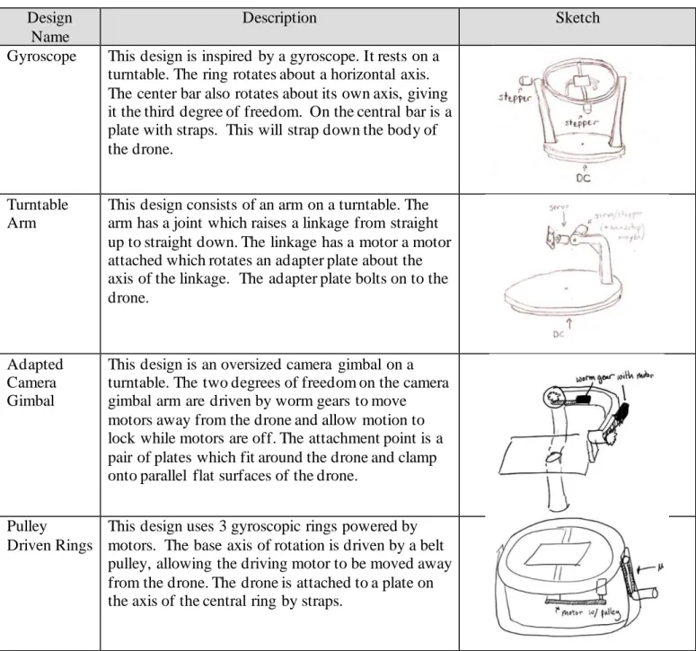
Table 6. Top Concept Designs
Design Name
Description Sketch
Gyroscope This design is inspired by a gyroscope. It rests on a turntable. The ring rotates about a horizontal axis. The center bar also rotates about its own axis, giving it the third degree of freedom. On the central bar is a plate with straps. This will strap down the body of the drone.
Turntable Arm
This design consists of an arm on a turntable. The arm has a joint which raises a linkage from straight up to straight down. The linkage has a motor a motor attached which rotates an adapter plate about the axis of the linkage. The adapter plate bolts on to the drone.
Adapted Camera Gimbal
This design is an oversized camera gimbal on a turntable. The two degrees of freedom on the camera gimbal arm are driven by worm gears to move motors away from the drone and allow motion to lock while motors are off. The attachment point is a pair of plates which fit around the drone and clamp onto parallel flat surfaces of the drone.
Pulley Driven Rings
This design uses 3 gyroscopic rings powered by motors. The base axis of rotation is driven by a belt pulley, allowing the driving motor to be moved away from the drone. The drone is attached to a plate on the axis of the central ring by straps.
These first four concepts were put into a weighted decision matrix in Table 7. This compared each design to a datum design in terms of the requirements specified during the problem definition portion of this report. To determine the score for each design, certain criteria required basic engineering analysis while others were scored qualitatively. In this case, the design datum is the gyroscope design because it was the most likely design to proceed with. After the scores were multiplied by the weighted
12
Table 7. Decision Matrix
Criteria Weight Gyroscope
Turntable Arm
Adapted Camera Gimbal
Pulley Driven
Rings
Low Cost 2 0 1 0 -1
Compact 2 0 1 1 -1
Robust 3 0 -1 -1 -1
Manufacturable 4 0 1 1 -1
Vibrations 5 0 -1 -1 0
Survive Elements 2 0 0 0 0
Weight 3 0 1 1 -1
Power Consumption 1 0 -1 -1 -1
Accuracy 4 0 0 0 1
Reliability 4 0 -1 -1 1
Total 0 -2 -4 -7
4.4 The Decision and What Follows
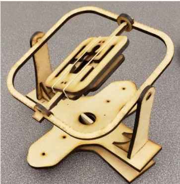
The purpose of these preliminary designs is to obtain feedback and receive confirmation from Inspired Flight to move forward with a single design. The two competing designs are the gyroscope and the turntable arm. Concept prototypes were made of each design in order to gain a clearer understanding of the pros and cons of each. These can be seen in Figure 4, Figure 5, and Figure 6. After further
consideration and prototyping both designs, the gyroscope design was chosen. A high-level CAD model of the chosen design was then created in SolidWorks.
4.4.1 Mechanical Design
The gyroscope shown in Figure 4 holds the drone in the center plate. It offers 3 degrees of freedom (DOF) and supports each component with two points of contact. We plan to drive each joint with a motor. In this design, the center of the drone rests on the axis of rotation for all yaw, pitch, and roll. We also see that the motor on the middle ring may be difficult to power and that clearances in all
Figure 4. Concept prototype for the gyroscopic design, laser cut from MDF
14
Figure 5. Concept prototype for turntable arm, laser cut from MDF
From the physical prototypes, the nuances of each design become clear. The gyroscopic design has some key benefits. The gyroscope inherently positions the drone’s center of gravity over the axis of rotation, where the turntable arm cannot do so in all orientations. Both designs will allow the necessary degrees of freedom to orient the drone for calibration; however, the turntable arm is expected to experience a much greater moment on the arm of the device, possibly increasing the amount of power required to run the motors and inducing stability issues. The turntable arm also requires actuators to be much closer to the drone itself, which may cause magnetic interference. The turn table has the benefit of positioning the actuators on one side of rotation, meaning that the wiring required for the motors will not become
entangled with the rest of the device. The turn table also has a more structurally simple design and may require less complex manufacturing.
We plan to move forward with the gyroscopic design due to the aforementioned benefits. A preliminary CAD model of this can be seen in Figure 6. We believe that the benefits that the turntable arm offer do not outweigh the strengths of the gyroscopic design. This design will allow a more stable orientation processes and offers more support during calibration. To manufacture the curved geometries required for the gyroscope the team plans to use the waterjets available on campus. For smaller, lower risk
components of the device, the team has access to various 3D printers across the Cal Poly campus and at Inspired Flight.
Figure 6. Isometric concept CAD model of gyroscope device
4.4.2 Electronic Hardware Design
The calibration device will require several electronic hardware components for full autonomous functionality. Of these, electronic actuators are of particular importance. We are currently considering stepper motors, servo motors, DC motors with encoders, or some combination of the three for our design. This design decision will be finalized as the mechanical design is further analyzed, and the torque and accuracy requirements become clear.
The controller for the device will require serial communication in order to properly interface with the QGroundControl software running on the computer as well as the ability to send the appropriate control signals for the decided motors. For prototyping purposes, the team is planning to use an Arduino Uno with a motor driver shield due to its to adaptability and ease of use as well as its wide range of functions. In order to measure the orientation of the system for feedback and control, the device will utilize the measurement system of the actuators with the possible addition of an IMU for more verification of the orientation.
4.4.3 High Level Software Design
16
Table 8. List of expected program tasks and their functions
Task Name Function
1 Master Mind Ensure cooperative function between all tasks.
2 Motor Control Control operation of the motors
3 QGroundControl
Interface
Communicate with QGroundControl in and update the calibration device on the current state of calibration
4 Measurement Measure the current state and physical orientation of the device
An initial state diagram of the Master Mind task can be seen in Figure 7. This Figure also shows the general process that the device will use to calibrate the drone. The device will first initialize and then wait for a signal from QGroundControl that signifies that the calibration processes has been started. Once this signal is received, Master Mind will signal the motors to begin operation so that the drone is properly oriented for a specific calibration. The measurement task will report the current orientation of the system and the Master Mind task will automatically begin the calibration processes. Once the correct orientation has been reached, either the base rotation will occur, or the drone will be held still. Once each calibration step has been completed, the calibration device will reorient and repeat until the entire calibration process is complete.
Figure 7. Diagram of General Organization of Calibration
4.5 Preliminary Analysis
The analysis for the turntable arm was modeled like a cantilever beam, which would produce much higher moments at the arms joint. This could also lead to larger deflections and increased susceptibility to vibration. These observations along with the overall user interaction with the prototypes swayed our decision towards the gyroscope design. The preliminary calculations are shown in Appendix E. The calculations show that the torque needed to rotate the balanced gyroscope design is within the range of commercially available stepper/servo motors.
4.6 Design Hazards and Unknowns
As part of our initial design proceses, a design hazard checklist was completed to identify any potential dangers our device may pose. The completed checklist can be found in Appendix F. The rotation of the device is a potential source of injury because of the pinch points it may create. To minimize this risk, the final design will include an emergency stop that will cease all operations of the device as well as labels identifying the danger this device imposes.
As previously discussed, challenges we expect to face with our design are handling magnetic interference and driving the joints of the device. We are unsure how much of an effect the magnetic fields generated by the electronic actuators of the device will have on the sensors of the uncalibrated drone and would like to perform additional testing. The unusual orientations required of the device for the calibration process may also pose a challenge when trying to attach actuators. Mounting motors in a compact manner without interfering with the rest of the device may be difficult and while there are devices (i.e. slip rings) that allow electric signals to be passed through rotational joints, further ideation is required for this aspect of the design. More detailed analysis must be done on the physical design to define the torque requirements (both dynamic and static) of the motors as well as the required strength of materials that will comprise the device.
5.0 Final Design
The Final Design section of this report details the design choices we made when further specifying the preliminary design as well as all changes made to the design during manufacture and assembly. Images of the entire design as well as more detailed views of important subsystems are included. Also included are samples of the calculations done to ensure that the design will meet each of the engineering
specifications that were determined.
5.1 Mechanical Design Model and Diagrams
This section outlines the design of the physical structure of the drone calibrator. First, it discusses the intended design, and then it notes the changes made in the final construction of it.
5.1.1 Original Structural Design Goals
Images of CAD models showing the complete product, as well as more detailed images of smaller subsections and components are contained in this section. It is meant to provide a visual representation for our plan for the verification prototype. Additionally, Appendix G contains an exploded view of the structure.
18 more detail in Figures 8-12. The three axes of rotations have also been in Figure 8. The primary axis of rotation rotates the outer fork, inner ring and drone mount system. The second ary axis of rotation, which lies through top of the fork system, rotates the inner ring and drone mount system. The tertiary axis of rotation acts through the inner ring and rotates only the drone mount system. The combination of these rotations nested within one another, allow for the drone to be placed in any orientation.
Figure 8. Mockup of Structural Prototype Design
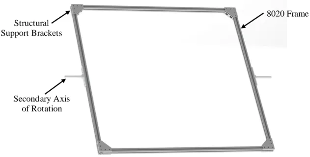
Figure 9 shows the extent of what we decided to make for the structural prototype. The prototype includes two main subassemblies, the inner ring and outer fork, which cover a broad range of items to test for the final assembly. The useful concepts that this prototype will be proving, and testing will include controlling two motors simultaneously, spinning a large part of the frame, and passing signal and power wires through a slip ring.
Inner Ring Subsystem
Drone Mount Subsystem
PRIMARY AXIS OF ROTATION
Outer Fork Subsystem
Figure 9. Overall View of Structural Prototype
Figure 10 shows the inner ring for the structural prototype which contains four equal lengths of 8020 fastened together to form a square. The ring is rotated by the hex shaft which is mounted to a connector plate fastened to the outside of the 8020.
Figure 10. Inner Ring Subsystem on Structural Prototype
The fork subsystem is shown with motors attached at the ugly joints in Figure 11. This fork system has been assembled as part of our structural prototype. Once the components have been tested, this fork will be integrated into our final prototype.
Inner Ring Subsystem
Outer Fork Subsystem
8020 Frame
20
Figure 11. Outer Fork Subsystem on Structural Prototype
Figure 12 shows many of the critical components of the design as it is how the rotation about the axis is generated. The three mounting plates are all custom manufactured, but all other components were purchased. The stepper motor is geared down with a high precision gearbox to create adequate torque as well as decrease the speed. The slip ring allows for electrical circuits to be passed through the rotating joint, allowing for the motors on the tertiary axis to be powered. The motors drive a hex shaft, so the attachment to the ring is more secure and can transmit more torque.
Figure 12. Detail View of the Secondary Axis Joint
Nema 17 Stepper Motor
100:1 Gearbox
Motor Mounting Plate
8-Wire 10A Slip ring
Slip ring & Bearing Mounting
Plate
½” Hex Shaft
Hex Shaft Mounting Hub
Inner Ring Adapter Plate Secondary Axis
Joint
8020 Frame
21 5.1.2 Final Structural Result
During Winter Quarter of the project, building the prototype taught us quite a bit about the functionality of the system and led us to make a few major alterations to the design. We will now discuss these alterations that make up the final design of the physical calibration system. A rendering of the final design, labeled to show these changes can be seen below in Figure 13.
Figure 13. Rendering of Final Design
First and foremost, we decided to move to having one motor driving each axis instead of two. We were initially concerned that the motors would not provide enough torque alone. However, through testing, we determined that the torque was sufficient. Additionally, with two motors, wiring would be an issue because driving two motors with one driver proved to be ineffective.
Next, we decided to cut the drone mounting plate from plywood to test with, and with the COVID 19 pandemic, we could no longer manufacture the ½” polycarbonate sheet we purchased. Additionally, we decided that since the drone we wanted to mount was rapidly changing at Inspired Flight, it did not make sense to cut up a $300+ sheet of polycarbonate that could be useless on the finalized version of the drone anyways. We were able to use plywood to make a drone mounting plate perfect for the aircraft we were given to test with. The manufacturing section (6.2) of this report contains instructions to cut the mounting plate from polycarbonate, as that would be a better solution for a finalized product.
After constructing the prototype, we also decided to add structural support to the fork. The triangular 45o
supports we added gave the entire frame more stability, especially while accelerating.
Next, the electronic hardware, namely the three motor drivers and the Arduino (discussed in the next section) needed a permanent home. We designed and 3D-printed a mounting bracket for the motor Single Motor
Driving each Axis
Temporary Wooden Mounting
Plate
PRIMARY AXIS OF ROTATION
Proximity Sensors on each
Axis
Driver/Arduino Mounting Bracket Redesigned
Primary Axis Motor Assembly Added
22 drivers and Arduino that mounts in one of the inside corners of the base. Because the mount was
essentially a cantilevered beam, we decided to print the bracket using polycarbonate filament, ensuring strength and rigidity. A close-up rendering of this assembly can be seen in Figure 14.
Figure 14. Close-up of Driver Mount Assembly
The next realization we had was that the system needed feedback for each axis’ orientation. We
determined the best way to accomplish this was by using proximity sensors that send an electrical signal to the computer when close to a magnet. Using the same polycarbonate filament, we designed and printed brackets for the proximity sensors, ensuring that each sensor was the proper distance from its corresponding magnet. Each sensor and magnet has a mounting bracket attaching to the 8020 frame, apart from the tertiary axis magnet, which was screwed into the corner of the drone mounting plate. Two of the three axis’ sensors/magnets can be seen in Figure 15.
Figure 14. Close-up of Proximity Sensors
Driver Mounting Bracket
Motor Drivers Arduino Uno
Secondary Axis Magnet Secondary Axis
Sensor
Tertiary Axis Magnet
Lastly, the biggest change to the final design was the primary axis motor assembly. When researching the best way to transfer torque from the primary motor to the 8020 of the fork, we quickly realized that there are no standard or existing assemblies that make this possible. We had to be creative with the torque conversion and ended up using multiple diameters of parts, tying them together with a custom turned shaft. A section view of these assembled parts can be seen in Figure 16.In summary, the primary motor is mounted to the underside of the base via a custom 3D-printed polycarbonate mounting plate. The motor’s 15mm shaft is then inserted into a 15mm coupling. The custom keyed shaft is has a diameter of 15mm at one end, which is inserted into the opposite side of the 15mm coupling. The
custom shaft must then travel through a slip ring, which has an inside diameter of 12.7mm. To make this possible, most of the shaft is turned from 15mm to 12.7mm. To join properly with a 14mm flanged shaft mount (attached to the 8020 of the fork), a brass sleeve adaptor bushing( 108) is placed on the end of the shaft to bring the diameter back to 14mm. The brass sleeve (108) (ID=12mm, OD=14mm) must be drilled out to 12.7mm on the inside to fit over the shaft, and a 5mm slot must be milled along the length of the sleeve to provide clearance for the key on the shaft. There will then be two of these keys (5mm x 5mm) that are pressed into both sides of the shaft, allowing torque to be transferred. Although the torque is transferred completely through this shaft, the shaft bears none of the fork’s weight. To eliminate rotational friction while bearing the load of the fork, a sleeved turntable was placed between the base and the fork and is attached independently to both. This essentially allows the fork to be supported by the turntable and turned by the shaft assembly.
24 5.2 Final Electrical Design
In this section, the final electrical design is discussed. We will compare aspects of the original design to what we were able to implement in the final prototype.
5.2.1 Original Electrical Design Goals
The electrical design will consist of three motors and the supporting electrical hardware. Each axis will be driven by its own individual motor. The wiring will be routed along the appropriate beams and through the base and fork joints using slip rings. Motors on the same axis will be driven by the same signal. It has yet to be determined if this signal can be from one motor driver or two motor drivers receiving the same signal. This will determine the need for either three or five motor drivers. The signals to the drivers will be sent by an Arduino Uno and which will be connected by USB to a control
computer. The wiring diagram is included in Appendix H. Regarding power, the Arduino will be powered by the computer and the motors will be powered by an exterior power supply through the motor drivers.
5.2.2 Final Electrical Result
After testing the structural prototype, it was determined that only a single motor was required for each axis. A NEMA 17 stepper motor with a 100:1 precision gearbox drives the tertiary and secondary axis. A NEMA 34 stepper motor with a 20:1 precision gearbox is used to drive the primary axis. One motor driver per motor is used, as per our original design. An emergency stop was also added to the system for a quick shutdown of all motors. When activated, the emergency stop shorts the MF- pins on the motor drivers to ground, deactivating the motor drivers.
5.3 Final Software Design
The software which we designed is in two parts. The first is written in Python. This will run on the controlling computer and will interface with the PixHawk (the drone module being calibrated), run the Master Mind code, and communicate over serial with the Arduino Uno. The second portion of software to design will be in C++ on the Arduino Uno. This code will interpret motor commands from the controlling computer and send them to the motor drivers. Figure 17 shows a communication diagram between the drone, computer, and Arduino.
5.3.1 Original Arduino Software Design Goals
The Arduino code is broken into states. The states are shown below in Figure 18. In the first state, each of the three axes is run until it detects a reed switch, then it rotates to the starting position for calibration. In state 1, it waits for a command from the computer running the Master Mind python code. Positive one will spin the primary axis for about seven seconds. Positive and negative two will spin the secondary axis in either direction 90o, same for positive and negative 3 for the tertiary axis. To turn the motors on
and off, the commands are 8 and 0 respectively. For each of the spin commands, (-3, -2, -1, 1, 2, 3), the code advances to state two ramp up to speed, state three to turn the appropriate amount, and then state four to ramp to a stop, returning to state one to await another command. Upon entering each state, the Arduino will send its current state to the Master Mind python code for verification.
26 5.3.2 Arduino Software Results
Our Arduino code functions largely the same as originally designed. An additional software state was added for more functionality, which can be seen in Figure 19. This state, which is state 5 in the code, runs the motors one at a time until the reed switch on each axis is triggered. Once triggered, the motor will orient the axis to its starting position. This orientation state can be accessed by sending the Arduino a spin command of 9. This allows for the machine to be re-oriented at any time. A change to the overall structure of the organization of the Arduino code was also made. Originally, the Arduino only checked for a command while state 1. This functionality was changed to happen every cycle of the Arduino. This allows for a 0, or stop command, to be received and interpreted at any time. All other commands are only interpreted in state 1. The complete documented Arduino code can be found in Appendix I.
5.3.3 Original Master Mind Design Goals
Figure 9 shows the state diagram of Master Mind. Master Mind must calibrate four sensors. For each calibration, a similar path, focusing on the motors, is displayed below. The “Orient” state will signal the motors to move the drone to each of six orientations. The “Hold” state will be a delay for the PixHawk Module to calibrate. The “Rotate” state will rotate the base while the PixHawk calibrates. Once each sensor is calibrated, Master Mind will move on to the next sensor calibration.
Figure 19. Original Master Mind State Diagram
5.3.4 Master Mind Results and Organization
The final python code consists of three tasks and a application to run the guided user interface (GUI). The GUI is shown in Figure 21. The guided user interface is created using Tkinter. One task handles the communications with the Arduino over a serial connection. The second task communicates with the PixHawk through serial communication. By sending commands directly to the Nuttx shell running on the PixHawk, this task can initiate the calibration process on the drone.The python script is also able to read the feedback from the Nuttx shell to determine if the system is ready for the next step in the calibration process. By doing this, we are using MAVLink and not MAVSDK. The third task, Master Mind is the most complex and we will be discussing it in depth.
28 Overall, the Master Mind task is organized in 13 states, which can also be seen in Appendix J. Each sensor in the flight controller has two corresponding states, an orient state and a hold state; each orient state has substates corresponding to the different orientations the system must reach before completing calibration. The messages displayed in the GUI that correspond to the calibration are set in the
initialization substate. Master Mind then transitions to the hold state, where it sends the appropriate message to start the sensor calibration on the PixHawk. Once the calibration has been started, Master Mind continues to read the messages from the PixHawk until it receives a confirmation that a sensor is done calibrating, or a side is done. It will then transition back to the orient state from there either increment substates or move on to the next sensor. This repeats for each of the four sensors. The states and substates are largely controlled by the spin and readPX4 function. The entire python code can be found in Appendix I.
There are several functions created for Master Mind. The spin function sends a command to the Arduino to initiate a movement on the calibration machine. This spin function has some additional functionality that affects the transitioning between states. If the spin function is called while the Arduino is not in state 1, it will set a global flag to true, indicating that the Arduino has started a movement. If the
movement flag is true and the Arduino is back in state 1, this indicates that the machine has just finished a movement. In this case, if the spin function is called it increments the state of the Master Mind,
increments the substate of the system, and resets the relevant flags to prepare for the system to send a new movement to the Arduino. This function takes in the current substate and the desired Arduino movement as inputs.
The readPX4 function interprets the global variable PXmsg. It takes no arguments but simply changes the states of the system based on the messages received from the drone. If the message from the PixHawk begins with a warning or error, it will display the appropriate message and reset the program. Otherwise, if the message is relevant to the progress of the calibration, it will change the Master Mind state and set the appropriate flags. In these cases, there are several options for what the message could be. The string “progress <100>” indicates that the current calibration has been completed. In this case the done flag will be set to true and the state will be decremented by one if Master Mind is in the “hold” stage. The “side done” message acts largely the same as the “progress <100>” message but sets the sideDone flag rather than the done flag. This message corresponds to the magnetometer and
accelerometer calibrations, as they must be calibrated on multiple sides before being considered fully calibrated. If the message contains the string “7 s”, the PixHawk is prompting the user to spin the drone for seven seconds. This message only appears when calibrating the magnetometer. The flag spinReady is set, indicating that the primary axis is actively spinning, and Master Mind waits in the spin state before moving back to the orient state to reorient. More details and troubleshooting tips are included in the Operator’s Manual in Appendix K.
5.4 Preliminary and Design Tool Calculations
To ensure that our motors were properly sized and that our structure would not bend excessively or break, we completed torque and bending calculations. We started these on paper so we could have sketches, free body diagrams and the equations written out, then we programmed a design tool in Excel to run these calculations so that we could change numbers easily to test and modify different theoretical possibilities. The hand calculations and design tool screen shots can be found in Appendix E.
29 size our motors due to their weight and torque outputs for the desired RPM (revolutions per minute) of each axis.
We had structural concerns as well that we wanted to check on paper before buying all of materials for a structural prototype. We needed to make sure that the hex shafts on the secondary axis (connecting the motors to the bracket on the ring) weren’t going to bend and that the 8020 that makes the base of the fork wouldn’t flex either. These were done with two similar calculations which used the respective material properties and inertia calculations to find max bending for both cases. We used a design factor of two in order to ensure our design will operate safely. The maximum deflection that will be
experienced by the hex shaft is 0.0042mm and the maximum deflection of the bottom of the fork is 0.39mm. We were comfortable with both of these numbers, so we decided to go ahead with our design.
5.5 Safety and Maintenance
In order to ensure our device is safe and usable we completed a failure mode and effects analysis (FMEA). From the FMEA we determined the most likely and catastrophic failures and developed plans that would ensure the likelihood and impact of these failures would be minimized.
Based on the likelihood of failure and the severity of the failure, our highest priority was ensuring that vibrations do not affect the calibration of the drone. The potential causes of failure are a weak
connection between the drone and the mounting plate, attachments that are too flexible, or an incorrectly loaded drone. The action that we will take to prevent these issues is prototyping and testing the drone mount and analyzing the data collected from the calibration logs. In the event that a component fails, we expect to replace it, as most parts are off-the-shelf. If the 8020 beams flex too much under the required loads, we will add reinforcement to the structure, using the T-slot connections. Other safety
considerations and preventative measures can be found in the FMEA attached as Appendix L.
Components were chosen to be low maintenance to limit the amount of work required to keep the device functional. Further information about using and maintaining the drone calibrator are included in the Operator’s Manual in Appendix K. The only expected maintenance is checking the structural joint fasteners to verify they have not come loose over time.
5.6 Cost Summary
30 6.0 Manufacturing
This section describes our plan for manufacturing and assembling the design specified in Section 5. It contains details on the procurement and assembly of purchased components, as well as the machining of custom manufactured parts.
6.1 Procurement
To mitigate risks in manufacturing, we opted to make the verification prototype design out of as many off-the-shelf parts as possible. By using an 8020 T-slotted rail system, the design is very adjustable and modular. The goal was that if something did not work properly, we could swap it out for another modular part or assembly.
The companies we sourced parts from for the structural prototype were StepperOnline, McMaster-Carr, WCP, 8020.net, and Amazon. Appendix N is a prototype budget showing every part, vendor, and vendor item number needed to order the parts and materials necessary to build the prototype. Included in
Appendix N is also a table of links to where each component was sourced.
6.2 Manufacturing Instructions
We tried to keep the components that needed to be physically manufactured relatively small because custom machining and manufacturing is a large investment of time and can also be expensive. All major manufacturing of parts was done in the Cal Poly ME Machine Shops and at Inspired Flight, using equipment such as the waterjet, mills, lathes, and 3D printers. As mentioned above, the modularity of the prototype uses mostly off-the-shelf parts. Besides the cutting of the frame components, the only custom parts in the design were the connections between the frame and various components. Appendix O is a drawing package that includes all drawings needed for both manufacturing and
Table 9. Custom Manufactured Parts
Part Number Description
207 Slip Ring ½” Hex Shaft
901 Standard ½” Hex Shaft
902-1 Nema 17 Motor Mounting Plate
902-2 Bearing Mounting Plate
902-3 Slip Ring Bearing Support Plate
902-4 Inner Ring Shaft Mounting Plate
902-5 Turn Table Mounting Plate Base
902-6 Turn Table Mounting Plate Fork
902-7 Flanged Hub Adapter
403 Plate Mounting Bracket
914-1 Base Proximity Sensor Mount V1
914-2 Fork Proximity Sensor Mount V1
914-3 Ring Proximity Sensor Mount V1
914-4 Driver Mounting Plate
914-5 Primary Motor Mounting Plate
106 Primary Shaft
402 Drone Mounting Plate
108 Adapter Bushing 12-14mm
With part drawings in hand, follow these instructions to manufacture each part. Slip Ring ½” Hex Shaft: 207
a) Start with 18” length of ½” hex shaft (ordered from WCP) b) Cut length of shaft to 4.5” on a chop saw or vertical saw
c) Turn outside of shaft on lathe according to dimensions on drawing
d) On the lathe, drill hole into end of the same side of shaft according to dimensions on drawing Standard ½” Hex Shaft: 901
a) Start with 18” length of ½” hex shaft (ordered from WCP) a) Cut length of shaft to 4.5” on a chop saw or vertical saw
b) On the lathe, drill hole into end of the same side of shaft according to dimensions on drawing Nema 17 Motor Mounting Plate: 902 - 1 (Note: Cut out multiple plates at once to maximize use of material)
a) Start with 12”x12” sheet of ¼" thick aluminum (ordered from McMaster) b) Cut plate on waterjet cutter (engineering drawing dimensions in inches)
c) On a drill press, re-drill the four outer holes to the dimensions shown on drawing d) On a drill press, re-drill the inner four-hole pattern to the dimensions shown on drawing e) On a drill press, countersink the inner four-hole pattern to the dimensions shown on drawing
Bearing Mounting Plate: 902 - 2 (Note: Cut out multiple plates at once to maximize use of material)
32 c) On a drill press, re-drill the four outer holes to the dimensions shown on drawing
d) On a mill, cut down the material directly around the inner hole by the depth listed on the drawing. Note: if done manually, do not worry about overshooting the specified milled profile, as it merely provides clearance for the bearing’s flange
Slip Ring Bearing Support Plate: 902 - 3 (Note: Cut out multiple plates at once to maximize use of material)
a) Start with 12”x12” sheet of ¼" thick aluminum (ordered from McMaster) b) Cut plate on waterjet cutter (engineering drawing dimensions in inches)
c) On a drill press, re-drill the four outer holes to the dimensions shown on drawing
d) On a mill, cut down the material directly around the inner hole by the depth listed on the drawing. Note: if done manually, do not worry about overshooting the specified milled profile, as it merely provides clearance for the bearing’s flange
Inner Ring Shaft Mounting Plate: 902 - 4 (Note: Cut out multiple plates at once to maximize use of material)
a) Start with 12”x12” sheet of ¼" thick aluminum (ordered from McMaster) b) Cut plate on waterjet cutter (engineering drawing dimensions in inches)
c) On a drill press, re-drill the four outer holes to the dimensions shown on drawing d) On a drill press, re-drill the inner four-hole pattern to the dimensions shown on drawing e) On a drill press, countersink the inner four-hole pattern to the dimensions shown on drawing
Turn Table Mounting Plate Base: 902 - 5 (Note: Cut out multiple plates at once to maximize use of material)
a) Start with 12”x12” sheet of ¼" thick aluminum (ordered from McMaster) b) Cut plate on waterjet cutter (dimensions in inches)
c) On a drill press, re-drill the six outer holes to the dimensions shown on drawing d) On a drill press, re-drill the six-hole ring pattern to the dimensions shown on drawing e) On a mill or by hand, ream the large inner hole to the dimensions shown on drawing
Turn Table Mounting Plate Fork: 902 - 6 (Note: Cut out multiple plates at once to maximize use of material)
a) Start with 12”x12” sheet of ¼" thick aluminum (ordered from McMaster) b) Cut plate on waterjet cutter (dimensions in inches) using a .dxf file
c) On a drill press, re-drill the four outer holes to the dimensions shown on drawing
d) On a drill press, re-drill the small four-hole pattern to the dimensions shown on drawing e) On a mill, ream the inner-center hole to the dimensions shown on drawing
Flanged Hub Adapter: 902 - 7 (Note: Cut out multiple plates at once to maximize use of material)
a) Start with 12”x12” sheet of ¼" thick aluminum (ordered from McMaster) b) Cut plate on waterjet cutter (dimensions in inches) using a .dxf file
c) On a drill press, re-drill the two outer holes to the dimensions shown on drawing
Plate Mounting Bracket: 403 (Note: Cut out multiple plates at once to maximize use of material)
a) Start with 3”x1”x1.7” block of aluminum
e) On a mill, chamfer the top and side edges of the part
Base Proximity Sensor Mount V1: 914 - 1
a) Start with a 3D printer and polycarbonate filament (ordered from Amazon) b) 3D print part using .stl file
c) Ream all 8020 .275” holes with a .275” drill bit d) Ream all 1/8” holes with a 1/8” drill bit
e) Using a larger drill bit, lightly counter-sink the mounting side of the 1/8” holes for easier assembly
Fork Proximity Sensor Mount V1: 914 - 2
a) Start with a 3D printer and polycarbonate filament (ordered from Amazon) b) 3D print part using .stl file
c) Ream all 8020 .275” holes with a .275” drill bit d) Ream all 1/8” holes with a 1/8” drill bit
e) Using a larger drill bit, lightly counter-sink the mounting side of the 1/8” holes for easier assembly
Ring Proximity Sensor Mount V1: 914 - 3
a) Start with a 3D printer and polycarbonate filament (ordered from Amazon) b) 3D print part using .stl file
c) Ream all 8020 .275” holes with a .275” drill bit d) Ream all 1/8” holes with a 1/8” drill bit
e) Using a larger drill bit, lightly counter-sink the mounting side of the 1/8” holes for easier assembly Driver Mounting Plate V1: 914 - 4
a) Start with a 3D printer and polycarbonate filament (ordered from Amazon) b) 3D print part using .stl file
c) Ream all 8020 .275” holes with a .275” drill bit d) Ream all 1/8” holes with a 1/8” drill bit
e) Using a larger drill bit, lightly counter-sink the mounting side of the 1/8” holes for easier assembly
Primary Motor Mounting Plate: 914 - 5
a) Start with a 3D printer and polycarbonate filament (ordered from Amazon) b) 3D print part using .stl file. Engineering drawing also has dimensions c) Clean up by hand with a de-burring tool and sandpaper
Primary Shaft: 106
a) Start with 300mm length of 15mm diameter steel keyed shaft (ordered from McMaster) b) Cut length of shaft to 114.30mm (or 4.5”) on a chop saw or vertical saw
c) On a lathe, turn down an 89.3mm length of the shaft to 12.70mm
d) On a lathe, turn down the chamfer on the large diameter side of the shaft (Note: we used the preexisting chamfer on the shaft that came from the manufacturer)
e) Fit custom sleeve over the 12.70mm end
f) Insert key into keyway and custom adaptor bushing (108)
Drone Mounting Plate: 402
a) Start with provided 24” x 48” x .5” sheet of polycarbonate
34 c) Ream all .275” holes with a .275” drill bit
Adapter Bushing 12-14mm: 108
a) Start with a 12-14mm adapter bushing (ordered from McMaster) b) Drill out the inside diameter to 12.7mm using a mill
c) To cut out the key slot, clamp the bushing on the flat ends between parallels in a mill and use a 5mm end mill to cut a thru slot all the way down the length of the bushing
The drawing package in Appendix O also contains a drawing that lists the dimensions to cut each length of 8020. Table 10 is a table of each part and length required for the prototype:
Table 10. 8020 Cut Lengths for Verification Prototype
Part Number Description Length Quantity
8020-1 Turntable Horizontal Supports 24 in 6
8020-2 Turntable Horizontals long 22 in 4
8020-3 Turntable Horizontals short 20 in 4
8020-4 Turntable Verticals Supports 8 in 4
8020-5 Corner Verticals Supports 9 in 4
8020-6 Fork Arms 33.5 in 4
8020-7 Fork Base 50.5 in 2
8020-8 Ring Motor Supports 3.0 in 4
8020-9 Ring Arms 42.5 in 4
8020-10 Fork Corner Supports 12 in 4
6.3 Assembly
The drawing package (Appendix O) also contains the exploded drawings needed for assembly. With these drawings in hand, and optionally the SolidWorks model open, follow the procedure for each subsystem to assemble the prototype:
Assemble the Fork
Parts required: 505, 904, 901, 903, 902-1, 902-3, 207, 902-4, 905, 906, 914-2, 6, 7, 8020-10, 801, 802, 805, 806, 804
a) Acquire the two bottom rungs of the fork (8020-7)
b) Attach them together with a 3x1” gusset bracket (804) and T-nuts and bolts on the top edge at both ends of 8020 lengths
c) Acquire the four arm sections of 8020 (8020-6)
d) Attach one to each end of the two bottom rings at a right angle. Use the T-nuts and bolts to secure them to the 3x1” gusset brackets already in place. Also add four frame corner fasteners (801), one to the exterior side of each segment joint. Note that the T-nuts may have to be slid in to place before all bolts have been completely tightened (especially for step g).
f) Add a custom slip ring bearing support plate (902-3) at the top edge of the interior face of each of side of the fork (2 plates total) with T-nuts and bolts. Ensure the counter sinks are facing toward the frame structure and the cable routing holes are oriented as shown in the exploded view.
g) Add the Frame Corner Supports (8020-10) and Diagonal Brace Ends (807), attached with T-nuts and bolts, to inside the bottom corners of the fork’s frame structure as 45° diagonal supports. h) Add fork proximity sensor mount V1 (914-2) with T-nuts and bolts to the side of the structure.
Assemble the Ring
Parts Required: 505, 904, 901, 903, 902-1, 902-2, 403, 914-3, 8020-9, 8020-8, 803, 801, 905, 906
d) Acquire the four side lengths of the ring (8020-9).
e) Attach together in a square using the 2” gusset brackets (802), T-nuts, and bolts. Ensure the corners are staggered correctly to create a true square and not a rectangle (A single length of 8020 should on have one other piece butted up to its cut end, the other end should be open for T-nut insertion. f) Add four frame corner fasteners (801), one to each corner with T-nuts and bolts. Ensure that the
appropriate number of T-nuts have been put in the slot before tightening as two of the T-nuts for each corner must be slid in from the opposite end of the 8020 length.
g) Flip the ring over and add four more frame corner fasteners (801) in the same manner.
h) Attach two inner ring shaft mounting plates (902-4) to non-adjacent sides of the ring and secure the hex shafts from the fork to the ring using the hex clamping hubs (903).
i) Drill a 9/16” hole in two of the 8020-9 parts at the midpoint of the ring edge (not the center of the 8020 length). These will be adjacent to the lengths mentioned in part e). This will be for the hex shafts to pass through so they can attach to the bearing mounting plates (902-2) on either side. j) Tap each end of the all four ring motor supports (8020-8) with an ¼” - 20 tap. Then use frame corner
fasteners (801) to attach two ring motor supports (8020-8) above and below the midpoint holes on the side lengths (8020-9). Do this on both sides of the ring.
k) Secure the bearing mounting plates (902-2) on each side of the ring motor supports (8020-8). l) One side of the ring will have a Nema 17 motor mounting plate (902-1) instead of the outermost
bearing mounting plate (902-2) to allow the Nema 17 motor (505) to be mounted.
m) Attach the two hex shafts (901): one hex shaft to the bearings in the bearing mounting plates (902-2) on one side of ring and the other hex shaft to the opposite side of the ring to the Nema 17 motor (505)
n) Add ring proximity sensor mount V1 (914-3) with T-nuts and bolts to the side of the structure
Assemble the Base
Parts Required: 506, 102, 103, 104, 105, 106, 107, 108, 109, 902-5, 902-6, 902-7, 909, 910, 911, 914-1, 914-4, 914-5, 8020-1, 8020-2, 8020-3, 8020-4, 8020-5, 802, 110
a) Acquire the 8020 lengths required (8020-1, 8020-2, 8020-3, 8020-4, 8020-5) and piece together the base structure attaching with 16 frame corner fasteners (801), 24 gusset brackets (802), and needed T-nuts and bolts. Ensure that the appropriate number of T-nuts have been put in the slot before tightening as some of the T-nuts for each corner must be slid in from the opposite end of the 8020 length