APPLICATION NOTE
SAFETY PRECAUTIONS FOR DEVELOPMENT TOOL
TRIAC + MICROCONTROLLER
INTRODUCTION
The goal of this paper is to analyse the different ways to configure a micro-controller and a development tool during the debugging phase.
The major problem is due to the direct connection of the computer I/O lines with the mains power. Some precautions have to be taken during the emulation in order to avoid destruction.
LOW COST POWER SUPPLY
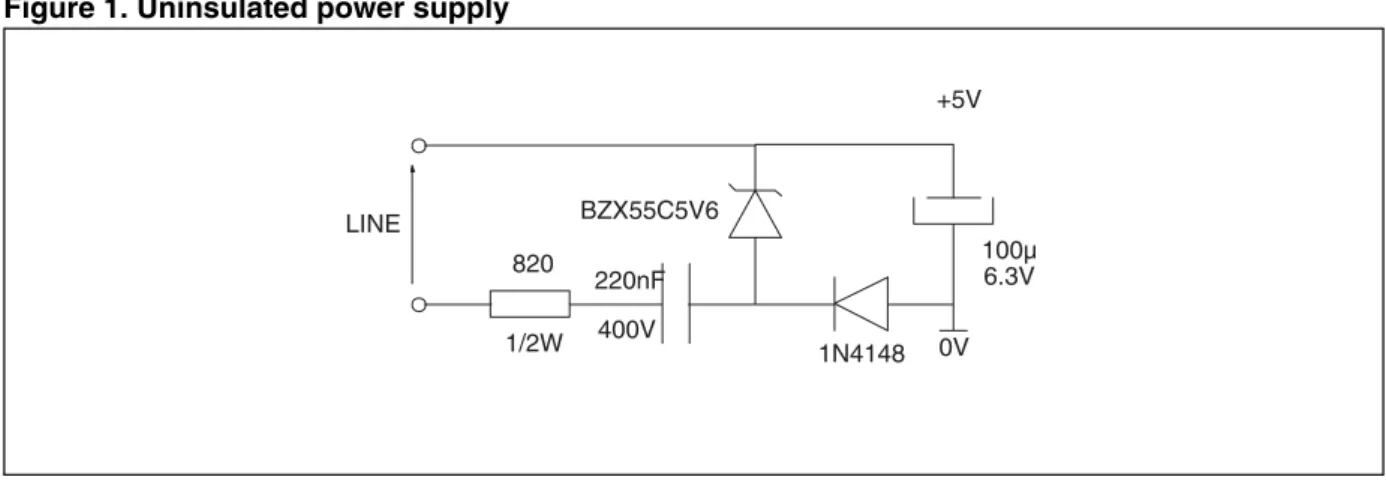
In most low cost applications the step down transformer is not used and the power supply delivers low current, as shown for example in Figure 1.
Figure 1. Uninsulated power supply
In domestic appliance applications, one of the most important power switches is the triac.
The function of driving the triac becomes more and more complex. For this reason, microcontrollers are becoming more and more common. Furthermore, sensitive triacs with high commutation parameters, for example LOGIC LEVEL triacs can be triggered directly by the microcontroller without any buffer. Sensitive triacs and microcontrollers allow decrease in power consumption.
In this way the power supply can be optimized to reduce the cost. Optimisation can be achieved by remov-ing the transformer.
The consequence is that there is no insulation, the microcontroller is connected directly on the line! When the software is emulated on the application board, the output port (RS232 port) of the computer is connected on the line via the emulator.
If some precaution is not taken "something" will be destroyed!
820 1/2W
220nF 400V BZX55C5V6
1N4148
100µ 6.3V 0V +5V
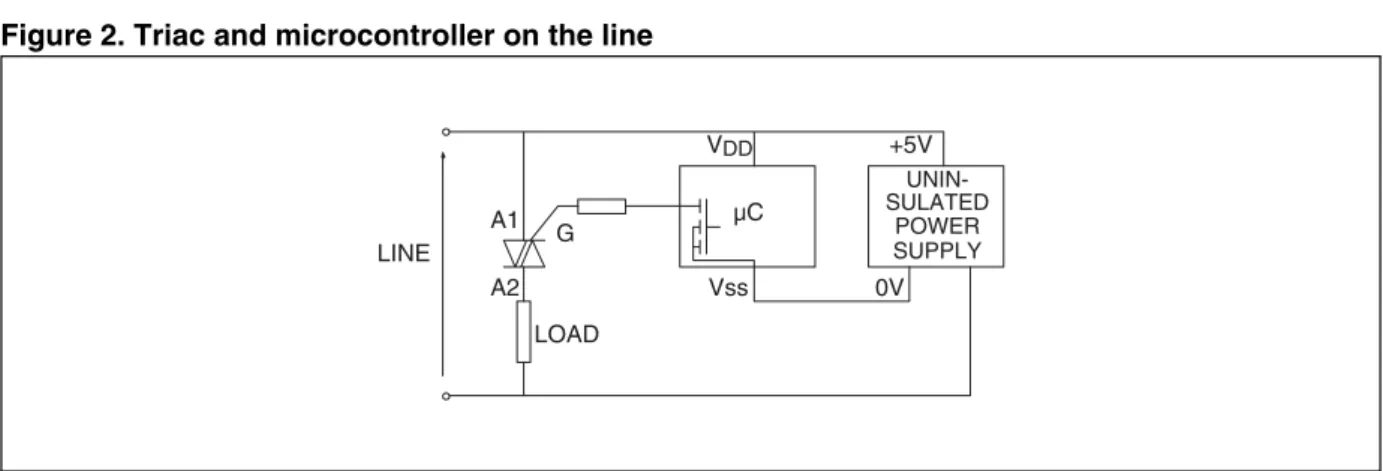
Figure 2. Triac and microcontroller on the line
In this case the micro-controller is supplied by an uninsulated +5V power supply connected directly to the line, and a low level (0V) on the output ports of the micro-controller is needed to trigger the triac.
USE OF A DEVELOPMENT TOOL
During the debugging phase, the micro-controller is removed and is replaced by the emulation probe. The circuit corresponding to the emulation phase of the previous example is shown in Figure 3.
The line is connected directly to the +5V of the emulator and a high (destructive) current can flow through the emulator and/or the computer.
Figure 3. Circuit without protection (Beware: this circuit is dangerous)
INSULATED SYSTEM
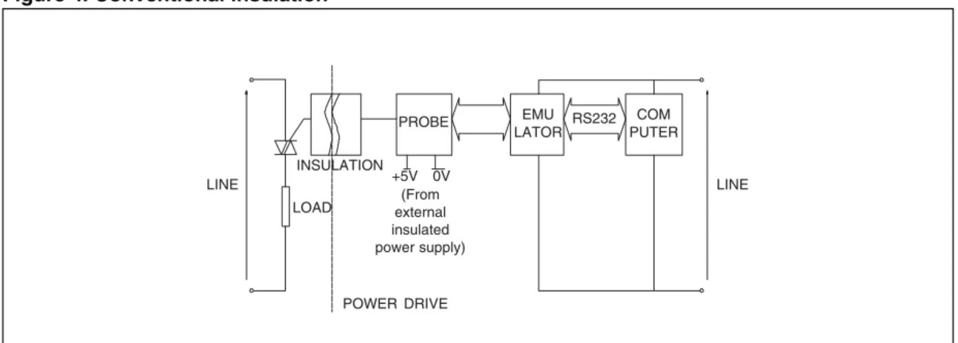
To avoid destruction of the development tool it is necessary to have an insulation between line and probe. This insulation can be achieved by optocouplers, pulse transformers, or insulation transformers.
Figure 4 shows the topology of the most common insulation.
G A1 A2 LOAD Vss VDD µC 0V +5V POWER SUPPLY LINE UNIN-SULATED LINE LOAD POWER SUPPLY PROBE EMU LATOR COM PUTER RS232 0V +5V +5V
WARNING
Figure 4. Conventional insulation
Optotriac
Figure 5 shows the circuit with triac and optotriac. The triac is working in the 1st and in the 3rd quadrants.
Figure 5. Optotriac drive
The main advantage of a such system is the low cost of the optotriac, but it needs an isolated auxiliary power supply.
For a zero crossing optotriac, the triac is triggering with a gate current equal to the gate trigger current with a very low dIG/dt. This does not allow high di/dt at turn on. That is to say the control of high current resistive load is not recommended with this method.
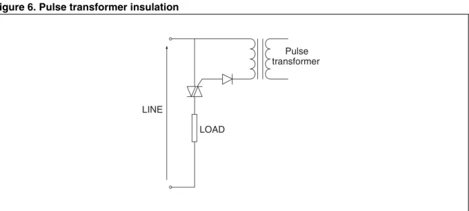
The pulse transformer
Figure 6 shows the circuit with a triac and a pulse transformer.
LINE
LOAD
PROBE EMU LATOR
COM PUTER +5V 0V
INSULATION
POWER DRIVE
LINE (From
external insulated power supply)
RS232
LINE
LOAD 100
LINE
LOAD 100
Figure 6. Pulse transformer insulation
This system is simple to use when the triac was initially driven by a buffer transistor, but it needs an ex-ternal power supply. The high dIG/dt through the gate allows high current resistive loads to be driven. Due to the saturation of the magnetic material, this system cannot drive small loads because the gate current is cancelled before the latching current has been reached.
For more information refer to the application note "Triac control by pulse transformer". The line insulation transformer
In the previous examples, the insulation was between the triac and the microcontroller.
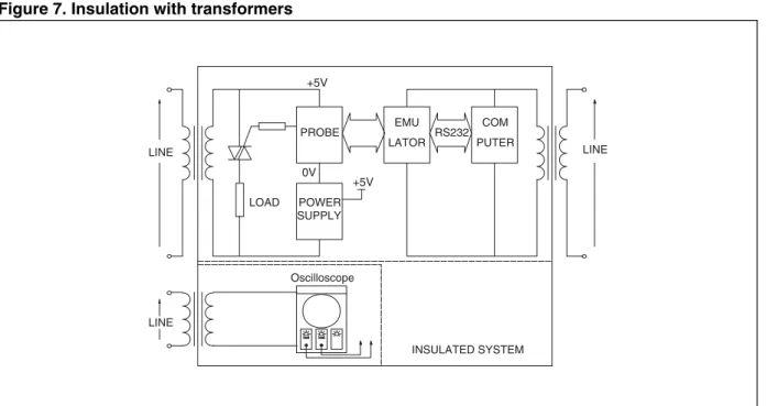
Another solution is to supply each equipment connected to the board from the mains through an insulation transformer. If an oscilloscope is used, it also has to be separately insulated.
The main advantage of this system is that we do not need to modify the target system during the debug-ging phase and it can be used with the microcontroller.
When a transformer is used between line and triac it should be noted that the line impedance is modified and then the behavior of the triac, load and line set can be different (waveform of current).
LINE
LOAD
Pulse transformer
Figure 7. Insulation with transformers
SUMMARY
New LOGIC LEVEL and SNUBBERLESS triacs can be connected directly to the microcontroller without buffers or insulation.
Furthermore, low cost power supplies without a transformer are becoming more common. There is an in-creasing number of applications supplied directly from the mains, and the microcontroller is directly con-nected to it.
During the debugging phase when connecting the development tool, a galvanic insulation is absolutely necessary.
This insulation can be done in 3 ways: 1. With optotriacs:
– Need modifications on the target system – Need external power supply
2. With pulse transformer:
– Need modifications (transistor to drive the pulse transformer) – Need an external power supply
– Cannot drive small loads 3. With insulation transformer :
– No modification on the application board.
– Modification of the line impedance due to the transformer between line and load.
Therefore a microcontroller operating on the mains with a triac may be directly connected to the line.
LINE LINE
+5V +5V
PROBE
POWER SUPPLY
EMU LATOR
COM PUTER 0V
LOAD
RS232
INSULATED SYSTEM LINE
REVISION HISTORY
Table 1. Revision History
Date Revision Description of Changes
May-1992 1 First Issue
Information furnished is believed to be accurate and reliable. However, STMicroelectronics assumes no responsibility for the consequences of use of such information nor for any infringement of patents or other rights of third parties which may result from its use. No license is granted by implication or otherwise under any patent or patent rights of STMicroelectronics. Specifications mentioned in this publication are subject to change without notice. This publication supersedes and replaces all information previously supplied. STMicroelectronics products are not authorized for use as critical components in life support devices or systems without express written approval of STMicroelectronics.
The ST logo is a registered trademark of STMicroelectronics. All other names are the property of their respective owners