7 Level Hybrid Neutral Point Flying Capacitor Multilevel Inverter
D Parvathi Devi*1 K Anil Kumar2
M.Tech Student, Department of EEE, KIET, Kakinada, India.1 Asst. Professor, Department of EEE, KIET, Kakinada, India.2
Abstract-This work proposes another seven-level hybrid topology joining components of neutral point braced and flying capacitor inverters. The proposed topology gives a tradeoff between various part checks to accomplish a decent loss dissemination, evade coordinate arrangement association of semiconductor gadgets, keep the adjusted operation of dc-connection capacitors while keeping the quantity of expensive segments, for example, capacitors and switches low. The required balance methodology is created and the operation of the proposed topology is contemplated. The elements of the proposed topology are examined and contrasted with other accessible topologies. Reenactment results are given to check the execution of the converter for medium voltage applications. Recreation comes about check through MATLAB/SIMULINK condition.
Key words- flying capacitor, Neutral point, Matlab.
INTRODUCTION
Multilevel inverters have picked up enthusiasm amid the most recent three decades because of the expanding interest for medium to high voltage converters for an assortment of high power applications. Diverse topologies have been proposed to fit the prerequisites of various applications. For medium voltage inverters, Cascade H-connect (CHB), impartial point clipped (NPC), and flying capacitor (FC) are the essential topologies. Among them, NPC and FC give a typical dc-interface which is a strict prerequisite for some applications. FC inverter utilizes capacitors to create yield voltage levels. The accessibility of intra-phrasal excess states in this topology can give both capacitor voltage adjusting and control misfortune circulation among switch. Be that as it may, expanded number of flying capacitors at larger amounts that builds the underlying expense and support extra charges and reductions the dependability of the inverter alongside the capacitor pre charge in a few applications are the principle disadvantages of this topology.
NPC inverter utilizes diodes to brace the voltage levels produced at the dc-interface capacitors to the yield.
Inordinate number of diodes, lopsided operation of dc-connection's voltage divider capacitors, and uneven dissemination of misfortune among switches are significant issues of this topology. Space vector calculations are accessible to ease the uneven misfortune and capacitor voltage issues in view of the inverter's working condition. Dynamic NPC (ANPC) enhances the misfortune appropriation of NPC by supplanting diodes with dynamic switches giving option unbiased point way.
Half and half topologies are suitable arrangements where higher number of levels is required. Joining the benefits of CHB, FC, and NPC, half breed inverters can give misfortune and voltage adjusting while at the same time keeping the quantity of segments low. Cases of half and half topologies joining FC and NPC can be found in , some of which has effectively discovered mechanical applications. The 5-level FC-ANPC is a case of cross breed topologies that advanced toward the business. The ACS2000 group of medium voltage drives, popularized by ABB, utilizes this topology with both dynamic and uninvolved front end arrangements. The primary preferred standpoint of this topology is the utilization of a solitary flying capacitor to create the yield five levels. Contrasted with different topologies that give a typical dc-connect, FC-ANPC has given an adequate tradeoff between the cost, execution, and dependability for 5-level applications. The burdens of FC-ANPC are high number of switches, arrangement association of high voltage switches, and poor misfortune conveyance.
This venture proposes another 7-level crossover topology in view of FC and NPC inverters. The objective of the proposed topology is to defeat the weaknesses of the conventional FC-ANPC. In this way, similarly, the proposed topology gives better misfortune dispersion, stays away from direct arrangement association of high voltage switches, and wipes out 2 switches per stage leg. These points of interest come at the cost of an extra capacitor and 6 diodes. In any case, the lifetime of every capacitor is relied upon to delay because of the half cycle operation and lower rms current.
In this venture, the design and operation of the proposed topology is portrayed in segment II. In segment III, related bearer based and non-transporter based balance
7 Level Hybrid Neutral Point Flying Capacitor Multilevel Inverter
D Parvathi Devi*1 K Anil Kumar2
M.Tech Student, Department of EEE, KIET, Kakinada, India.1 Asst. Professor, Department of EEE, KIET, Kakinada, India.2
Abstract-This work proposes another seven-level hybrid topology joining components of neutral point braced and flying capacitor inverters. The proposed topology gives a tradeoff between various part checks to accomplish a decent loss dissemination, evade coordinate arrangement association of semiconductor gadgets, keep the adjusted operation of dc-connection capacitors while keeping the quantity of expensive segments, for example, capacitors and switches low. The required balance methodology is created and the operation of the proposed topology is contemplated. The elements of the proposed topology are examined and contrasted with other accessible topologies. Reenactment results are given to check the execution of the converter for medium voltage applications. Recreation comes about check through MATLAB/SIMULINK condition.
Key words- flying capacitor, Neutral point, Matlab.
INTRODUCTION
Multilevel inverters have picked up enthusiasm amid the most recent three decades because of the expanding interest for medium to high voltage converters for an assortment of high power applications. Diverse topologies have been proposed to fit the prerequisites of various applications. For medium voltage inverters, Cascade H-connect (CHB), impartial point clipped (NPC), and flying capacitor (FC) are the essential topologies. Among them, NPC and FC give a typical dc-interface which is a strict prerequisite for some applications. FC inverter utilizes capacitors to create yield voltage levels. The accessibility of intra-phrasal excess states in this topology can give both capacitor voltage adjusting and control misfortune circulation among switch. Be that as it may, expanded number of flying capacitors at larger amounts that builds the underlying expense and support extra charges and reductions the dependability of the inverter alongside the capacitor pre charge in a few applications are the principle disadvantages of this topology.
NPC inverter utilizes diodes to brace the voltage levels produced at the dc-interface capacitors to the yield.
Inordinate number of diodes, lopsided operation of dc-connection's voltage divider capacitors, and uneven dissemination of misfortune among switches are significant issues of this topology. Space vector calculations are accessible to ease the uneven misfortune and capacitor voltage issues in view of the inverter's working condition. Dynamic NPC (ANPC) enhances the misfortune appropriation of NPC by supplanting diodes with dynamic switches giving option unbiased point way.
Half and half topologies are suitable arrangements where higher number of levels is required. Joining the benefits of CHB, FC, and NPC, half breed inverters can give misfortune and voltage adjusting while at the same time keeping the quantity of segments low. Cases of half and half topologies joining FC and NPC can be found in , some of which has effectively discovered mechanical applications. The 5-level FC-ANPC is a case of cross breed topologies that advanced toward the business. The ACS2000 group of medium voltage drives, popularized by ABB, utilizes this topology with both dynamic and uninvolved front end arrangements. The primary preferred standpoint of this topology is the utilization of a solitary flying capacitor to create the yield five levels. Contrasted with different topologies that give a typical dc-connect, FC-ANPC has given an adequate tradeoff between the cost, execution, and dependability for 5-level applications. The burdens of FC-ANPC are high number of switches, arrangement association of high voltage switches, and poor misfortune conveyance.
This venture proposes another 7-level crossover topology in view of FC and NPC inverters. The objective of the proposed topology is to defeat the weaknesses of the conventional FC-ANPC. In this way, similarly, the proposed topology gives better misfortune dispersion, stays away from direct arrangement association of high voltage switches, and wipes out 2 switches per stage leg. These points of interest come at the cost of an extra capacitor and 6 diodes. In any case, the lifetime of every capacitor is relied upon to delay because of the half cycle operation and lower rms current.
procedures are exhibited and altered to suit the proposed topology. Area IV gives a correlation between the proposed topology and different topologies that are accessible for 5-level setup. In segment V, the reenactment aftereffect of a contextual analysis is exhibited to check the operation of the proposed topology for medium voltage application.
II. THE PROPOSED TOPOLOGY AND OPERATION
The proposed topology incorporates a dc-connection that is normal among the three stages. The dc-interface gives three voltage levels +2E, 0, and - 2E for the stage legs. Since every one of the stages have comparative arrangement, just a single stage leg of the proposed topology has been appeared in Fig. 1. Every one of the parts appeared in the figure have rise to working voltage E i.e. one fourth of the dc-connect voltage Vdc. The flying capacitors CA1 and CA2 are controlled to remain charged at the objective voltage E.
The accessible conditions of one stage leg are appeared in table I. To create level 2E, all the top arm switches SA1, SA2, SA3, SA4 ought to turn on. For level E, two decisions are accessible i.e. either through dc-connection's sure point (EP) or through dc-connection's nonpartisan point (E0). This repetition can be utilized to adjust the voltage of CA1. Level 0 is created through clasping the dc connection's unbiased indicate the yield (00). Negative states can be produced comparably because of the symmetry of the topology.
The operation of this topology is basically like topologies, for example, stacked multicell (SMC) converter where the positive and negative stacks work autonomously. Henceforth, the positive stack capacitor CA1 is utilized and adjusted amid the positive cycle and rest amid the negative cycle, while the negative stack capacitor CA2 is utilized and adjusted amid the negative cycle and rest amid the positive cycle. Thus, the flying capacitors will see the exchanging recurrence as opposed to line recurrence and in this manner the capacitor size is not very huge. Like the three-level NPC inverter, if the three periods of the heap are adjusted, the nonpartisan point voltage will be consistent in principle.
Notwithstanding, the voltage may marginally float away because of the lopsidedness in the components' spillage current. Furthermore, albeit little, there is constantly some awkwardness among the stages. A steady voltage float, despite the fact that little, can cause higher voltage crosswise over piece of the gadgets which can be deadly. By the by, this float can be repaid by infusing a little regular mode to the three stages. An essential element of
among exchanging gadgets. Consequently, exchanging misfortune which is the significant constraining element of inverter's warm execution is conveyed among the switches. As the principle result, the tradeoff between exchanging recurrence and current de rating is made strides. This gives the chance to either build the appraised current and energy of the inverter or increment the exchanging recurrence bringing about lower capacitor measure and enhanced voltage waveform quality.
III. MODULATION TECHNIQUES
Different adjustment strategies might be adjusted for the proposed topology. Bearer based regulation with sinusoidal or altered reference and in addition non-transporter based procedures for example, space vector adjustment and particular consonant disposal might be utilized to produce the door signals. The decision of a balance method is generally a tradeoff among the necessities of the application, unpredictability of the product, and cost of the control equipment.
Fig. 1. A phase leg of the proposed 5-level hybrid topology
TABLE I.
Sʹ1, Sʹ2, Sʹ3, Sʹ4 are switched complementary to S1, S2,
S3, S4 respectively. i>0 represents outbound current and i<0 represents inbound current. N.A. stands for Not Affected. For the 7-level topology +3E and -3E states increasesand S5,S’5 switches&C3 capacitor increases.
A. Carrier-Based Modulation
Carrier set’s arrangement and reference waveform’s
shape are the main sources of varieties in carrier-based modulation techniques for multilevel inverters. As for
carrier set’s arrangement, level shifted carriers LSC and
phase shifted carriers PSC are the two main categories that are respectively suitable for diode-clamped and multi-cell structures. Two members in the LSC family, alternative phase opposition disposition APOD and phase disposition PD are
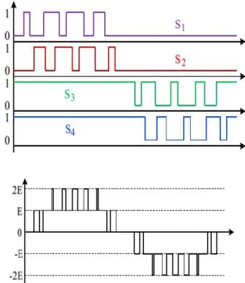
Fig. 2. Carrier- based modulation using PSC with sinusoidal reference for single phase application. (a) Reference and carriers arrangement. (b) Gate signals. (c)
Output waveform.
known to generate the best results for singe-phase and three phase applications, respectively. PSC in its original form has been shown to generate a PWM waveform that matches with APOD. Also a modified version of PSC with dynamic phase shift has been shown to match with PD [16]. The reference for single-phase applications is usually a simple sinusoidal waveform. For three-phase applications, a variety of reference waveforms are available due to thepossibility of common mode injection in three-phase structure. This flexibility has been used to serve different purposes such as increased dc link utilization, lower THD, lower Loss, and neutral point voltage control.
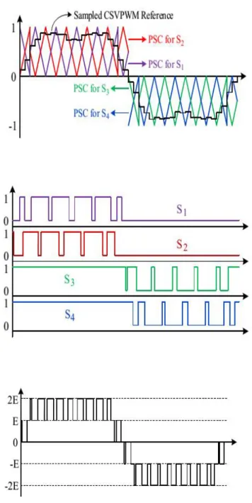
Fig. 3. Carrier-based modulation using modified PSC with sampled CSVPWM reference for three phase application.
(a) Reference and carriers arrangement. (b) Gate signals. (c) Output waveform.
For three-phase case, similar approach may be adopted except that, to generate a PD scheme equivalent, the
positive cycle carriers should have π/2 phase shift
compared to thenegative cycle carriers. Also, the carriers incorporate a dynamic phase shift which for sampled
reference waveforms always adds up by π/2 at the carrier
band transitions. For thereference waveform, centered
carrier period can provide similar output performance as SVM. Figure 4 illustrates the modulationtechnique using sampled CSVPWM along with modified PSC for the proposed inverter.
B. Non-Carrier-Based Modulation
For non-carrier-based modulation techniques such as SVM and SHE, the output PWM waveform may be generated first and then decomposed to the required switching signals. Figure 4 illustrates the required procedure to generate the gate signals for each phase leg. The 5-level PWM waveform is first separated to positive and negative cycle 3-level PWMs. Using state machine decoder, each cycle is then decomposed to two 2-level PWMs i.e. the required gate signals for each FC cell.
Fig. 4. Non-carrier-based modulation for a phase leg of the proposed inverter.
It is important to note that this procedure is independent of the adopted modulation technique. Therefore, it can be used with carrier-based modulation techniques as well as non carrier-based. This might be a good alternative when the complexity of the carrier-based technique is relatively high e.g. for PD scheme.
IV. COMPARISON WITH OTHER TOPOLOGIES
A Comparison between the proposed topology and different 5-level topologies in terms of component count and loss distribution is listed in table II. The 5-level NPC has low switch count but the major problems are unbalanced operation of dc-link capacitors, poor loss distribution among switches, and excessive number of diodes. 5-Level FC provides low switch count and excellent loss distribution but requires high number of flying capacitors that can adversely affect the initial cost, maintenance and replacement surcharges, and reliability
switch count and high frequency switches in series are the main issues of this topology.
The 5-Level FC ANPC provides a good balance between the number of semiconductors and capacitors. The major issue with this topology is the poor loss distribution among the switches. The topology proposed in this paper, provides a tradeoff between different component counts to achieve a good loss distribution, avoid direct series connectionof semiconductor devices, keep the balanced operation of dc link capacitors while keeping the number of costly components such as capacitors and switches as small as possible.
TABLE II. COMPARISON OF DIFFERENT TOPOLOGIES
The component counts in this table are per phase leg.
V. SIMULATION DESIGN AND RESULTS
To verify the operation of the proposed topology and the performance of the modulation techniques provided in section III, a model is developed and simulated with MATLAB software. The performance of the natural balancing technique for a three phase 12kV inverter supplying a 5MVA load at power factor of 0.7 is shown in Fig. 5. Centered space vector modulation (CSVPWM) is used at modulation index of 1.09
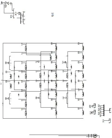
Fig6:SIMULATION BLOCK DIAGRAM OF 7-LEVEL INVERTER
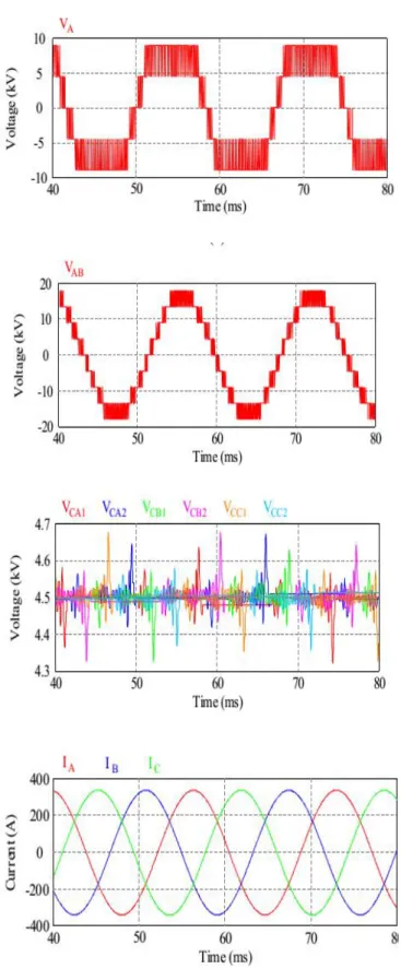
Fig. 8. Simulation results. (a) Phase voltage (b) Line voltage (c) Flying capacitor voltages (d) Load current frequency 5kHz. The dc-link voltage is set at 18kV and
flying capacitors are 330µF. It can be seen that even without an RLC balance booster, the capacitor voltage
errors are limited to less than 4%.
Fig. 9: Simulation results. (a) Phase voltage (b) Line voltage (c) Flying capacitor voltages (d) Load current frequency 5kHz
VI. CONCLUSION
REFERENCES
[1] Roozbeh Naderi and Keyue Smedley” A New Hybrid
Active Neutral Point Clamped Flying Capacitor
Multilevel Inverter”IEEE 2015
[2] S. Kouro, M. Malinowski, K. Gopakumar, J. Pou, L. G. Franquelo, J. Rodriguez, M. A. Pérez, and J. I. Leon,
“Recent Advances and Industrial Applications of
Multilevel Converters,” IEEE Trans. Ind. Electron., vol. 57, no. 8, pp. 2553–2580, Aug. 2010.
[3] M. Malinowski, K. Gopakumar, J. Rodriguez, and M.
A. Pérez, “A Survey on Cascaded Multilevel Inverters,”
IEEE Trans. Ind. Electron., vol. 57, no. 7, pp. 2197–2206, Jul. 2010.
[4] J. Rodriguez, “Multilevel inverters: a survey of topologies, controls, and applications,” IEEE Trans. Ind. Electron., vol. 49, no. 4, pp. 724–738, Aug. 2002.
[5] J. Rodriguez, S. Bernet, P. K. Steimer, and I. E.
Lizama, “A Survey on Neutral-Point-Clamped Inverters,”
IEEE Trans. Ind. Electron., vol. 57, no. 7, pp. 2219–2230, Jul. 2010.
[6] J. Rodriguez, S. Bernet, B. Wu, J. O. Pontt, and S.
Kouro, “Multilevel Voltage-Source-Converter Topologies for Industrial Medium-Voltage Drives,”IEEE Trans. Ind. Electron., vol. 54, no. 6, pp. 2930–2945, Dec. 2007.
[7] B. P. McGrath, T. Meynard, G. Gateau, and D. G.
Holmes, “Optimal Modulation of Flying Capacitor and
Stacked Multicell Converters Using a State Machine
Decoder,”IEEE Trans. Power Electron., vol. 22, no. 2, pp. 508–516, Mar. 2007.
[8] H. Sepahvand, M. Khazraei, K. Corzine, and M.
Ferdowsi, “Startup Procedure and Switching Loss
Reduction for a Single-Phase Flying Capacitor Active