Received dat e: 2002-07-17; R evision received dat e: 2002-03-11
Foundation item: A eronaut ical Science Emphasis foundation of China( 98Z52001) , D elt a Pow er Elect ronics Science & Education D evelopment Fund
A rt icle U RL: ht t p: / / ww w . hkx b. n et . cn/ cja/ 2003/ 02/ 0097/
Direct Torque Control System and Sensorl ess Technique of
Permanent Magnet Synchronous Motor
HU Y u-w en1, T IAN Cun1
, YOU Zhi-qing1
, T ang L i-xin2
, M . F . Rahman2 (1. A ero-P ow er Sci T ech Cent er, N anj ing Univer sity of A eronautics and
A st ronautics, N anj ing 210016, China)
(2. School of Elec. Eng. A nd T ele. , T he U niversity of N ew Sout h W ales, Sy dney A ustralia)
Abstract: T he direct torque contr ol theor y has achieved g reat success in the control of induction motor s. How ever, in the DT C dr ive system of Permanent M ag net Synchronous M achine ( PM SM ) pr oposed a few years ago, ther e are many basic theoretical problems that must be clarified. T his pa-per describes an investigatio n about the effect of the zer o voltage space v ector s in the DT C sy stem of PM SM and points out that if using t he zero voltage space vectors rat ionally , not only can the DT C sy stem be driven successfully but also the tor que r ipple is reduced and the perfo rmance of the sy stem is impr oved. T his paper also st udies the senso rless technique in the DT C system of P M SM and con-figures the DT C system o f P M SM w ith sensor less technique including zero voltage space v ecto rs. N umer ical simulations and ex per iment al tests have pr oved the theo ry corr ect . In the conditio n of sensor -less, the DT C sy stem of PM SM is wide-rang ely speed adjusting, and the ratio o f speed adjustment is 1∶100.
Key words: power electr onics; dir ect tor que contr ol; permanent magnet motor s; sensor less; st ator flux linkage 无速度传感器永磁同步电机直接转矩控制系统. 胡育文,田淳,游志青,汤立新, M . F . Rahman. 中 国航空学报(英文版) , 2003, 16( 2) : 97- 102. 摘 要: 详细阐述了零矢量在永磁直接转矩控制系统中的作用,指出如果合理应用零矢量,不仅能 使永磁电机( P M SM )的DT C系统正常运行,而且能减少转矩脉动的频率和改善系统的性能。还研 究了PM SM 的DT C系统的无速度 传感器技术,构建了包含零矢量在内的无速度传感器P M SM的 DT C系统。仿真和实验都证明了理论的正确性。在无速度传感器的条件下, PM SM 的DT C系统实 现了宽范围调速,调速比达到了1∶100。 关键词:电力电子; 直接转矩控制; 永磁电机; 无速度传感器; 定子磁链 文章编号: 1000-9361( 2003) 02-0097-06 中图分类号: T M 921. 5 文 献标识码: A
T he DT C for induction machines proposed in the middle of 1980' s has been used in many appli-cations already. In 1990' s, many at t empt s have been m ade to implem ent t he idea of the D T C of in-duction to PM SM , how ever, the current con-trollers w ere not eliminated in these st rategies and could not cont rol t he torque direct ly by volt ag e space vect ors[ 1]. Only the DT C theory of PM SM proposed in 1997 has t he same advant ag es as t he DT C of an induction machine[ 2]. N ot just so,
many potent ial advant ages w ere found in t his scheme: f or example, the f ield-w eakening cont rol becomes easier because the st at or flux linkage can be controlled direct ly in t he DT C syst em of a PM SM[ 3]; sensorless cont rol becom es possible be-cause t he met hod does not need accurate rot or posi-tion inf ormat ion. In recent y ears, the m odif ied st rat egy of the DT C sy stem of P MSM , w hich is named Space V ector Modulat ion ( SV M ) , has been st udied further to reduce the t orque ripple[ 4]. T his
is a st rat egy t o produce mult iple volt age space vec-tors in t he sampling int erval. For convenience, this st rat eg y is called SV M -D T C, and the t radi-tional st rateg y, w hich produces only one volt ag e space vect or, is called Basic DT C. How ever, t he DT C syst em of PMSM has many basic theoret ical problem s t hat hav e not been clarif ied yet. F or ex-am ple, what kind of role exact ly do t he zero volt-ag e space v ect ors play on t he DT C system of PM SM ? It show s clearly in R ef . [ 2] t hat zero volt-ag e space vectors should not be used in the DT C syst em of PM SM w hen Basic DT C is adopt ed; otherw ise, t he system cannot w ork properly. So, there are no zero voltage space vectors in t he corre-sponding sw itch table but six ot her volt ag e space vectors. How ever, for t he SV M-DT C, w hy does the syst em run in order when using t he zero volt-ag e space vect ors? Certainly, some abnormal st at us could be emerged w hile debug ging t he SV M -DT C control program. Is it because of t he zero volt ag e space vect ors? T herefore, w hat t he zero volt ag e space vectors act as in the DT C sy stem of PM SM is one import ant theoret ical problem. If t his prob-lem is not solved, it cannot be said t hat a perf ect theory on t he DT C of a PMSM is established.
T he sensorless cont rol is an import ant t ech-nique. In the F ield O rient ed Cont rol sy stem of PM SM , the sensorless cont rol scheme has been show n up in literat ure, while, in the DT C sy stem , it has just began t o be st udied. DT C does not need accurate rot or position information, w hich leads to much easier im plement of sensorless control in t he DT C than in the Field Orient ed Cont rol of PM SM .
T his paper w ill carry out deeply research f rom the aspects of basic t heory of DT C of PMSM and the sensorless cont rol, etc; at t he same t ime, a ra-tio of w ide-range speed adjust ment of 1∶100 is re-alized in t he experim ent device.
1
Basic T heory of DT C of PM SM
If controlling s, let s = const ant , and ne-glect ing the st at or resist ance, t he t orque of t he PM SM and it s diff erent ial coeff icient can bede-rived[ 2] T = 3 2p[ D(ixsin + iycos ) -Q(ixcos - iysin ) ] = 3 2p s iy ( 1) dT dt = 3p s 4LDLQ[ 2 fLQ cos -2 s (LQ- LD) cos2 ] = 3p s 4LD [ 2 fcos -2 s ( 1 - LD/LQ) cos2 ] ( 2) w herep is the N umber of pole pairs; sand fare t he st at or flux linkag e and rot or flux linkag e; D and Qare t he components of the st at or flux link-ag e on t he ax is of D andQ; ix and iyare the com-ponent s of t he axis of x andy. T he load angle is t he ang le bet ween t he stat or f lux s and f. Here,
f = constant , because the rotor is PM ex cit ed. LD, LQ are D-ax is and Q-ax is inductance respec-tively.
Eq. ( 2) implies t hat t he torque increases with t he increase in subject t o som e conditions. By changing quickly, the t orque can be changed quickly t oo.
In fact , any change consists of tw o part s: angular change sof sand ang ular change f of
f.
= s + f ( 3)
s can be cont rolled by select ing the proper volt age space vect ors. s= 0, w hen zero voltag e space vectors are select ed.
f is due t o the motion of t he rotor. T he fast er t he rotor rotat es, t he larger t he f is. If t he rotat ing speed is zero, f= 0.
2
Effect of the Zero Voltage
Space Vectors
= s+ f= ang (UiTs) - !fTs ( 4) w hereUi is a v olt age space v ect or; Ts is sampling int erval. If zero voltage space vectors are selected, t hen it is seen t hat = f= - !fTs. T his m eans t hat w ill decrease and hence the developed torque w ill be reduced, w hich is exact ly t he sam e as in t he induct ion machine syst em . T hus, it should be ac-cepted naturally t hat if t he cont rol mode of the
in-duction machine is adopt ed, the syst em would also w ork properly. A nd t hen, the cont rol switch table for t he positive direction operation is show n in T able 1. Ref . [ 2] indicat es t hat the syst em w ill be oft en in a prot ect ed condition and operat es out of order if P MSM is under the cont rol of t his t able.
Only w hen zero voltage space vectors are eliminat-ed, can t he motor w ork properly, t hat is t o replace T able 1 w it h T able 2. T he condit ion of t he neg a-tive direction is similar t o that of the posit ive direc-tion, w hich has been discussed above.
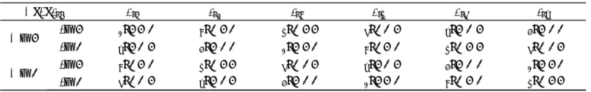
Tabl e 1 The switch tabl e for the positive direction operation
∀,#,∃(N) ∃( 1) ∃( 2) ∃( 3) ∃( 4) ∃( 5) ∃( 6)
∀ = 1 #= 1 U2( 1 1 0) U3( 0 1 0) U4( 0 1 1) U5( 0 0 1) U6( 1 0 1) U1( 1 0 0) #= 0 U7( 1 1 1) U0( 0 0 0) U7( 1 1 1) U0( 0 0 0) U7( 1 1 1) U0( 0 0 0)
∀ = 0 #= 1 U3( 0 1 0) U4( 0 1 1) U5( 0 0 1) U6( 1 0 1) U1( 1 0 0) U2( 1 1 0) #= 0 U0( 0 0 0) U7( 1 1 1) U0( 0 0 0) U7( 1 1 1) U0( 0 0 0) U7( 1 1 1)
The t able is exactly t he same as t he one in t he induct ion mot or[ 5].
Table 2 The switch table for the positive direction operation without using zero voltage space vectors
∀,#,∃(N) ∃( 1) ∃( 2) ∃( 3) ∃( 4) ∃( 5) ∃( 6)
∀ = 1 #= 1 U2( 1 1 0) U3( 0 1 0) U4( 0 1 1) U5( 0 0 1) U6( 1 0 1) U1( 1 0 0) #= 0 U6( 1 0 1) U1( 1 0 0) U2( 1 1 0) U3( 0 1 0) U4( 0 1 1) U5( 0 0 1)
∀ = 0 #= 1 U3( 0 1 0) U4( 0 1 1) U5( 0 0 1) U6( 1 0 1) U1( 1 0 0) U2( 1 1 0) #= 0 U5( 0 0 1) U6( 1 0 1) U1( 1 0 0) U2( 1 1 0) U3( 0 1 0) U4( 0 1 1)
In T able 1 and T able 2, ∀ and#are t he out-put s of the hyst eresis controller for t he flux linkag e and torque, respectively. If ∀ = 1, then the actual flux linkage is smaller t han the ref erence value. T he same is true f or the torque. ∃( 1)-∃( 6) are region numbers f or t he st at or f lux linkage positions[ 2, 5].
U0-U7are t he volt age space vect ors.
T herefore, Ref . [ 2] concludes t hat zero volt-ag e space vect ors w ork dif ferent ly in t he induct ion machine and PM SM, and zero voltage space vec-tors cannot be used in the PM SM . Ex planat ion cannot be given at t hat t im e, but experiment show s it clearly.
However, in recent years, zero voltage space vectors have been used again nat urally w ith sat isf y-ing experimental result s when SV M -DT C st rategy is studied further. Why do bot h t he experim ent s come t o t he contradictory conclusion? For the sake of the im provement of t he DT C t heory in PM SM , it is necessary t o make clear w hat role zero voltage space vect ors play on t he D T C syst em of PM SM.
sand fshould have t o be calculat ed care-fully in order to make clear the role of the zero volt age space vectors in sy nchronous m ot ors. It can be seen t hat w hen t he rot or speed is less t han, say , 5000 r/ min, fis so small t hat it can be ne-glect ed. F or example, if !f= 3000 r / min, Ts=
100%s, only equals - 1. 8°. If driving a heavy load, is about 90°, so t hat f/ = 2% , t here-fore, change of is very small. If !f= 300 r/ m in,
f/ = 0. 2% only. D ue t o t his reason, t he change of torque caused by f is also very small.
On t he ot her hand, according t o t he ex peri-mental result , average change of set of f by t he non-zero volt ag e space vect ors in sampling interval Ts, i.e. s, becom es about 9°-18°, which is 10-100 times t hat of f. T hus, the zero volt ag e space vectors in t he DT C sy stem of a PM SM hold t he t orque rat her than decrease it . T his is t rue on-ly in t he case t hat the rot at ing speed is not too high. If t he speed ex ceeds 10 000 rev/ min, de-creased t orque cont ribut ed by the zero volt ag e space vect ors w ill cause more t han 6°of chang e in during Ts of 100%s. T heref ore t he decrease in t orque cont ribut ed by t he zero volt age space vec-tors should be considered.
3
A Novel Cont rol Strategy of
DT C of P M SM
Considering t hat the zero volt age space vectors have t he ability t o hold t he f unct ion holding t orque. T his novel st rategy including zero volt ag e space vectors is show n below
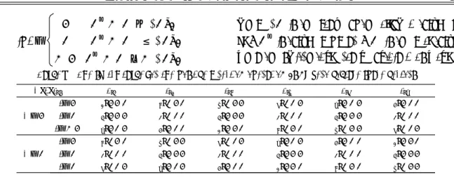
if #=
1 T*e - Te> T/ 2 0 T*e - Te ≤ T/ 2 - 1 T*e - Te< - T/ 2
w here T is the range of t he allow ed torque rip-ple; Te* is t orque reference; Teis the real torque. T hen t he sw itch table can be obtained as T able 3.
Tabl e 3 The switch tabl e f or the positive direction operation using zero vol tage space vectors
∀,#,∃(N) ∃( 1) ∃( 2) ∃( 3) ∃( 4) ∃( 5) ∃( 6) ∀ = 1 #= 1 U2( 1 1 0) U3( 0 1 0) U4( 0 1 1) U5( 0 0 1) U6( 1 0 1) U1( 1 0 0) #= 0 U7( 1 1 1) U0( 0 0 0) U7( 1 1 1) U0( 0 0 0) U7( 1 1 1) U0( 0 0 0) #= - 1 U6( 1 0 1) U1( 1 0 0) U2( 1 1 0) U3( 0 1 0) U4( 0 1 1) U5( 0 0 1) ∀ = 0 #= 1 U3( 0 1 0) U4( 0 1 1) U5( 0 0 1) U6( 1 0 1) U1( 1 0 0) U2( 1 1 0) #= 0 U0( 0 0 0) U7( 1 1 1) U0( 0 0 0) U7( 1 1 1) U0( 0 0 0) U7( 1 1 1) #= 0 U5( 0 0 1) U6( 1 0 1) U1( 1 0 0) U2( 1 1 0) U3( 0 1 0) U4( 0 1 1)
4
Sensorless Control T echnique
4.1 Orientation of the rotor pol e initial position In the DT C cont rol, only by t he acquisit ion of w hich region w here t he init ial posit ion of t he pole lies am ong the six regions, can the space volt ag e vectors be select ed. T herefore, com pared w ith t he Field Oriented Cont rol st rat egy , DT C strategy re-quest s much less accuracy of t he init ial posit ion, w hich is t he advant age of D T C strategy. U nder the situat ion that t he load is not aff ect ed by t he ini-tial rotat ing direct ion st rict ly, t he init ial posit ion w ill be orient ated easily by using the f ollow ing method.
Switch on t he lower IGBT of the phaseB and C, and at t he same time, control bot h the upper and the low er t ransist ors of t he phaseA in w ay of Chopping control ( t he dut y is 0. 1) . T hen t he flux linkage sw ill be formed in t he direct ion of axis A in t he motor, w hich causes the rot or pole t o turn to t he phase A of the motor, and the init ial posi-tion of the rot or pole is orient at ed simultaneously.
4.2 Sensorl ess control scheme
In t he st able condit ion, t he stator f lux linkag e of synchronous mot ors rotates at t he sam e speed as the rot or, that is !s= !r. In the static ax is of the stat or , t here is !s= d∃s dt = d dt arctan Q D = Q D- D Q 2 D+ 2Q for D = UD - iDRs Q= UQ- iQRs then !r = !s= (UQ - iQRs) D2 - (UD- iDRs) Q D+ 2Q
w hereUQandUDare t he com ponent s of the t erm i-nal voltageU on t he ax is of QandD, respect ively, w hich can be calculated by t heUDCon t he D C side and the space v ect ors in t he sam ple int erval; Dand Qare the cont rolling variables in t he DT C st rategy and have been calculat ed during t he cont rol. A c-cording to t he formula above, t he rotor rot at ing speed can be easily obt ained. However, it should be noted t hat the f orm ula only applies to calculat-ing t he rot at calculat-ing speed in t he stable condition. Be-cause !r is not equal to !s t otally in t he dynamic condit ion, some m odulat ion should have to be done.
5
Simulation and Experim ental T est
T he parameters of t he PMSM are given in t he appendix. T he block diagram of a P MSM drive w it h DT C is shown as Fig 1, w here the f lux est i-mator can be expressed as
D(k) = D(k- 1) + (UD(k- 1) - RiD)Ts Q(k) = Q(k- 1) + (UQ(k- 1) - RiQ)Ts
(k) = 2D(k) + Q2(k)
DSP T MS320C32 is used for real t im e cont rol of the PM SM.
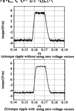
Fig. 2 is t he simulation result s of the torque ripple under the control st rat eg y including and ex-cluding zero voltage space vect ors, that is, Fig . 2 ( a) corresponds to the control method in T able 2 and Fig. 2( b) to that in T able 3.
Fig . 2 Simulation result s of tor que ripple It can be seen in t he f igure that the torque ripple is much more in the st rateg y w it hout using zero volt age space vectors t han t he one w it h using zero volt ag e space vect ors, w hich m eans that t he zero volt age space vect ors ex actly have the abilit y to hold t he funct ion holding torque. In t his w ay, the sw it ching t im es of t he transist or w ill be re-duced sharply, and t he consumption w ill be de-creased w it h lower dist urbance.
It also show s some simulation result s of t he dynamic response under t he cont rol strat egy in-cluding zero volt age space vectors. It can be ob-served that t he response t ime of t orque chang e from 5N m to - 5N m is 2ms only, which is t he sam e as t hat in t he cont rol w ithout using zero volt-ag e space vectors, and therefore, the dy namic re-sponse will not be w orsened by using zero volt ag e space vect ors.
Fig. 3 is t he experim ental result s of t he dy-namic response under the control strategy including
zero voltage space vectors. It is proved correct that t he response t ime of a t orque chang e f rom 5N m t o - 5N m is only 2ms, which is thoroughly sim i-lar t o t he results of simulation.
Ch1: tor que reference
Ch2: tor que response 1div = 4N m torque r esponse( - 5N m to 5N m) Fig . 3 T he experimental r esults
Fig. 4 show s t he speed-tracking curve of t he DT C sy stem of PM SM including t he zero volt ag e space vectors w ith using sensorless technique.
Ch1: speed r eterence 1div = 500r / min Ch2: speed r espo nse 1div= 500r/ min
Fig. 4 Speed-tracking curve in the sensor less conditio n It can be derived from t his figure that al-though the f ormula t o est im at e t he speed, which is adopt ed in t he sensorless cont rol, is relat ively sim-ple, it cont ribut es to a good performance when t racking the speed reference.
F ig . 5 Speed err or in the sensor less co ndition Fig. 5 indicates the speed error in t he DT C Permanent M agnet S yn chronous M ot or
syst em of PMSM w it h using sensorless cont rol. T his m otor' s rat ed speed is 1500 r/ min. It can reach t he max im speed 2000 r/ min w it h t he aid of t he field-w eakening cont rol, and can f all to the m inimum speed 20 r/ m in by using nov el f ilt er technique w hen t he mot or rotates at low speed. In the mot ion cont rol of this syst em , the ratio is up to 1!100, t he error ratio is less t han 2% and below 1% w hen the motor is running at high speed.
6
Conclusions
( 1) By dividing the control scheme of the torque to include regimes of increase, decrease and hold, and using t he zero voltage space vectors to hold t he t orque, t he DT C system of PM SM can not only w ork properly , but also improve t he per-formance of the syst em . T heref ore t he zero volt ag e space vect ors should be used and should not be for-saken, in t he D T C syst em of P MSM . T hus, one can draw t he conclusion that zero volt ag e space vectors should be used in t he cont rol of bot h Basic DT C and SV M -DT C, w hich w ill solve t he previ-ous cont radict ion.
( 2) Wit h t he help of t he f ilter, t he sensorless Basic DT C st rat egy including the zero volt ag e space vectors can decrease largely t he f requency of the t orque ripple and decelerat e to 20r/ min at low speed. T he rat io in t he m otion cont rol can reach 1 !100.
Appendix
Parameters of the machine used in simulation
Voltag eUn: 220 V Rated pow erPn: 1 kW
Rated speedWr: 1500 r/ min Rat ed curr entI: 2 A
D-axis inductanceLD: 0. 1133H Q-ax is inductanceLQ: 0. 1295H
Stato r resistanceRs: 20. 51& Magnet f lux linkage f: 0. 6115W b
Rat ed tor queT 5 N m Number of po le pairsp: 2
References
[ 1] French C, A carnley P. Direct t orque control of permanent magnet drive [ A ] . In Proc of IE EE Indust ry A pplication Societ y A nnual M eet ing[ C] . Florida, U SA , 1995. 199-206.
[ 2] Zhong L, R ahman M F, Hu Y W. A nalysis of direct t orque cont rol in permanent magnet synchronous drives[ J] . IEEE Trans on Power Elect ronics, 1997, 12 ( 3 ) : 529 -536.
[ 3] Rahman M F, Zhon g L, Lim K W. A direct t orque con-trolled in terior permanent magnet synchron ous m ot or drive incorporating f ield w eakening [ J ] . IEEE T rans On Indust ry A pplicat ions, 1998, 34( 6) : 1246- 1253.
[ 4] Tang L, Zh ong L, Rah man M F, et al. A novel direct t orque cont rol scheme for interior permanent magnet syn-chronous machine drive syst em w it h low ripple in torque and flux , and f ixed swit chin g f requency[ A ] . IEE E PES C, 33rd
[ C] . 2002. 529- 534.
[ 5] Takahashi I. A new quick-response and h igh -eff icien cy con-trol st rat egy of an induct ion mot or[ J ] . IEE E Trans on In-dustry A pplicat ion, 1986, 22( 5) : 820- 827.
Biographies:
HU Yu-wen Bo rn in 1944, a pr ofesso r in the D epartment o f Electrical and Elect ronic Eng ineer ing . T el: ( 025 ) 4892867, E-mail: huy uw en @ nuaa. edu. cn.
TIAN Chun Born in 1973, she
re-ceiv ed Ph. D. fro m N anjing U niv . of A er o. & A str o. in 2001. Her research interest is direct ed t owar ds electricit y and electr onics t echnolog y, mo dern technolo gy of speed regulation, etc.
YOU Zhi-qing Born in 1977, she r eceiv ed B. S. fr om N anjing U niv. of A ero. & Astro . in 2000. She is now studying fo r master deg ree.
Tang Li-xin He is now pursuing Doctor deg ree in Scho ol of Elec. Eng . & T ele of U niver sity of N ew South Wales, A ustralia.
M.F.Rahman He is a v ice pr ofessor in School of Elec. Eng. & T ele of U niver sity o f N ew South W ales, Sydney A ustralia.