40
© Global Society of Scientific Research and Researchers http://asrjetsjournal.org/
Image Processing Based Object Height Recovery to
Reconstruct 3D Objects
Dr. Ali Khleif
a, Mr. Ahmed Shnawa
b*
a,bProduction and Metallurgy Engineering Department, University of Technology, Baghdad-Iraq a
Email: [email protected]
b
Email: [email protected]
Abstract
An approach for automatic 3D object re-construction using object’s shadow. This research apply and utilize machine vision technology to develop a non-contact and rapid measurement system capable of measuring and reconstruct three-dimensional object attributes with an appropriate accuracy and to facilitating the possibility of reconstruction of three-dimensional objects by processing two-dimensional images. Machine vision consists of two main parts: the first part is eye in hand configuration that used to capture 2D image to the object from a top view with constant distance from the platform that carry the object. The second part is the light source which positioned at a predefined distance to generate shadow of object. To use this technology in an optimum way it needs image processing and computations in the form of a software that can meet our requirements of applying this technology. By using pixel by pixel scanning to extract image feature using MATLAB program and achieve image processing technique to get useful information from image very close to real measurements are gained. The technique is tested on three different objects that have different shape, size and material. The developed algorithm that make use of object height information for the directions associated with the incident light and the generated object shadows founded the maximum error in sample one is (0.0779) in length attribute and the minimum error that well be found (0.0543)in width attribute with sample two.
Keywords: Image Processing; computer vision; 3D object re-construction.
--- * Corresponding author.
41
1.IntroductionOne of the main challenges in modern machine vision is to develop techniques that are, inexpensive, fast and accurate can handle objects with arbitrary appearance and needed little or no user intervention [1]. Machine vision uses cameras, processing hardware and software algorithms to automate complex or mundane visual inspection tasks and precisely guide handling equipment during product assembly. With the development of the modern technology and industry, the performance and the reliability of the work pieces are more and more remarkably requested than before. Because the manual measurement which has some defects such as, slow efficiency, high cost, fatigability labor intensity and etc. all these defects are not able to content the need of the modern industry measurement, high precision and high efficiency. The vision measurement has incomparable virtues, such as consistency, accuracy, repetition and etc. Digital close range photogrammetry is extensively used because of its efficiency and significant decreasing time needed to collect data and process them and also applicability in different environmental conditions [2]. It is often the case that users create 3D object models using Computer Aided Design (CAD), however CAD systems require highly trained professional users and usually takes much time to create complicated models, hence they present a bottleneck in real applications [3]. Alternatively, vision-based techniques to obtain 3D object model data automatically by observing real objects may establish a beneficial solution that is of great significant in reverse engineering applications. Application of computer vision, shadow and 3D object reconstruction has been set as the common focus of many published articles. Kuang and his colleagues (2013) [4] discussed method based on the modulation of shadow areas by using the Otsu method to find out a threshold value and then use it to realize the binarization for the modulation image of the object extracted from the deformed fringes. The entire modulation distribution of the object can be used in pixel matching instead of the traditional marking method and finished the binarization for the modulation patterns with the Otsu method finding out the threshold value. By the correlation operation between the template cut from the first binarization pattern and the modulation of the other frame binarization patterns, the amount of the object shifting can be calculated. On this basis, pixel matching has been accomplished and the measured object can be reconstructed finally. This way can satisfy the demand of high accuracy and fast measurement. Tian and his colleagues (2014) [5] proposed method for extracting depth information with an aperture-rotating camera. The proposed method was applicable for arbitrary rotation angle by making use of pixel registration to get pixel shift angle, and calculating the pixel shift along this angle. Consumption time for shift angle was reduced by means of sampling. The proposed method was reduced the computation time from about 1 h to 1 min. Experimental results showed that the depth value have error of 5%. System. Chotikakamthorn (2015) [6] discussed the problem of near point light source location estimation. The process described in this research was based on a relationship between the cast shadow edge, the shadow casting surface, and the light source. The method works directly on optical-depth image pair available from an RGB-D camera. Experimental results with real images are included. Larger variation in the distance-type error was observed, that can cause noticeable difference in shadow. Zavala and his colleagues (2015) [7] presented a technique for 3D objects reconstruction using a webcam cameras to get sequence of images the cameras were mounted so that their axes remain orthogonal, both toward the subject. A mechanical device, controlled in angular position, allows movement of the webcam as they acquire an image sequence. Different views of the silhouette of the object were extracted from the images. The silhouettes processing to generate a 3D point cloud
42
and generate a mesh using Delaunay triangulation techniques. They performed the 3D reconstruction using a GUI developed in Visual C++ and also controlling the angular position of the cameras and the algorithm for the image processing. The results of the reconstruction process were modeled in a virtual environment to get a real view of the object. Gaoliang and his colleagues (2016) [8] proposed an on-line detection system based on computer vision to solve the instable and time consuming problem in detecting O-rings. They were used the detection algorithms based on computer vision technology to control the quality of O-rings. A machine vision system was evaluated through inspecting a series of O-rings by analyze the captured images and perform the measurement and inspection processes. Experimental results show the measurement accuracy rate of inner diameter with 95% and thickness with 100% was achieved. Khleif and his colleagues (2016) [9] proposed vision measurement system which consists of a camera carried on hand of a robot, which captured 2D image to the object from two sides with a constant distance of the objects. They used MATLAB program to achieve image processing. The resulted dimensions are found closer to real object dimensions that are measured using a digital vernier and 3d digital probe. Last step includes 2D image manipulating using the proposed algorithms to reconstruct the 3D objects depending on the resulted information (number of pixels). G. Wang and his colleagues (2016) [10] presented a new perspective shape from shading (SFS) for reconstructing the three-dimensional shape of hybrid surfaces. A hybrid reflectance model composed of a linear combination of Oren-Nayar model and Ward model was used to express the hybrid surfaces. A new imaging model incorporating a near point light source located at the optical center of the camera, a perspective camera projection, and the hybrid reflectance model was established. Image irradiance equation was formulated as a non-linear partial differential equation (PDE), which is related to a static Hamilton- Jacobi equation considering the boundary conditions. The viscosity solution of the resultant Hamilton-Jacobi equation was approximated by using numerical Hamiltonian and first-order and high-order fixed-point iterative sweeping method. Gadelmawla (2017) [11] presented a new non-contact automatic measurement system for measuring and inspecting various types of screw threads. Many image processing and computer vision algorithms have been developed to analyze the captured images and perform the measurement and inspection processes. 18 features could be measured by the proposed vision system. The system has been calibrated for both imperial and metric units, verified by measuring a standard ISO metric thread plug gage. After comparing the results of the measurements with the standard values, the maximum difference between the standard and measured values is ±5.4 𝜇𝜇m. Ahmed and his colleagues (2017) [12] developed stereo vision system to measure the distance of detected object without the need for pixel by pixel search methodology. The methodology consist of the system will implement equation for finding the real distance of detected objects, this detection done by feature extraction method. The system can be applicable in wide real life applications because of its high accuracy, low power consumes, cost effective and easy to be embedded with other systems such as navigation systems in robotic Experiments were performed on both synthetic and real images and the results demonstrate the effectiveness of the proposed approach.
2.Implemented vision system
A vision system consists of two main parts, hardware and a developed software, has been used. The hardware is used to capture images for objects to be measured and the software is used to analyze the captured images and perform the measurement and reconstruction processes. The vision system that was used in this paper consists of five components. This section describes the hardware setup used for the experimental work.
43
1- Camera with system for supporting it.2- Lighting with system for gripping it. 3- Personal computer with MATLAB.
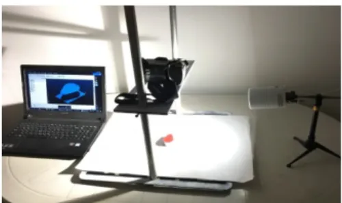
A hardware model is designed and built to simulate the function of the eye-in-hand configuration. A mechanical mechanism is constructed which can move in three linear movements and three rotational movements. This mechanism is referred to as the Cartesian mechanism. Figure (1) shows a photograph of the developed experimental setup.
Figure 1: A photograph of the experimental setup
2.1.System setup
As shown in figure (2), the hardware consists of three items. The first item is the Cartesian mechanism, this mechanism has the capability to move in x, y, and z directions. Also, rotational movements can be performed using the mechanism. The platform is a lower part which is made with (50 * 50 cm2 ) iron plate and thickness (4 mm) with tow slot to achieve y movement, it is fastened on a plane surface. The carriage or the tow bars carry the plane that hold the camera using a joint which allow both linear and rotational motion of the linkages. These linkages allow the camera holder to move in z and y directions, also the camera can move in x direction depending on the slot that hold the camera. A camera holder was developed to hold the digital camera, it can be fixed by using the bolt. The developed mechanism can be manually adjusted. The second item is a CCD color camera, in this work the images were acquired using a digital camera model Canon EOS 600D. This camera able to capturing images with a resolution of (3456 * 5184) pixels width and height respectively with 24 bit depth and 2.3 MB size using a JPG format. The third item is a lighting mechanism, is a light-emitting diode with (10) watt and cool white rays, in this work, the location of light source was verified first to achieve good post-processing of the image.
44
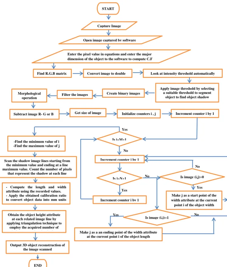
Figure 3: Flow chart of the adopted algorithm
3.The development algorithms for 3D shape reconstruction
The proposed technique acquires 3D features of the object using a single image. Several computer vision and image processing algorithms have been developed and applied to the captured image to perform the
Is i=M+1
Is j=N+1 Is image (i,j)=0 -Find the minimum value of i
-Find the maximum value of j
Increment counter j by 1
Increment counter i by 1
Make j as a start point of the width attribute at the current point i of the object width Scan the shadow image lines starting from
the minimum value and ending at a line maximum value. Count the number of pixels
that represent the shadow at each line
- Compute the length and width attribute using the recorded values. - Apply the obtained calibration ratio to convert object data into mm units
Obtain the object height attribute at each related image line by applying triangulation technique to
employ the acquired number of i l i h h d
END
Is image (i,j)=1
Output 3D object reconstruction of the image scanned
START
Capture Image
Open image captured by software
Enter the pixel value in equations and enter the major dimension of the object to the software to compute C.F
Find R.G.B matrix Convert image to double Look at intensity threshold automatically
Apply image threshold by selecting a suitable threshold to segment
object to find object shadow Create binary images
Filter the images Morphological
operation
Subtract image R- G or B Get size of image Initialize counters i , j Increment counter i by 1
Make j as a an ending point of the width attribute at the current point i of the object length
No Yes No No Yes Yes Yes No
45
measurement and reconstruction processes. Figure (3) represent the flowchart of applying these algorithms.
3.1.Setting of the lighting system
Lighting is a very important factors in many machine vision applications, Correct lighting system can improve the contrast of input images greatly thus increasing the overall system performance, the image is very sensitive to the lighting, so the type and position of light is very effected on the quality of image. The lighting system which uses a single light source, therefore, set in an oblique direction relative to the horizon. A close distance to the scene is implemented in the light setup, hence, only parallel light rays may be assumed to intercept the object. Reflected light is then reaching the camera due to the diffused reflection, to overcome this phenomenon the object was coated by spray cans colored red to avoid the reflected and shiny. Where adequate intensity is gained. , location of lighting source plays an important role in applications of object extraction. Figure (4) illustrates the effects of lighting position on the object extraction process. Where at each captured image the location of lighting source goes further away of object. In figure (4), the process of object extraction is enhanced at each location until certain position, where more increase in height will lead to inaccurate object extraction. This can be explained as follows: when lighting source goes away from the object, the area of the projected light will increase but the light intensity will decrease, and these effected on images when to separated it to binary”.
a) b) c) d)
Figure 4: Effect of lighting position on objects a) near light, b) parallel rays light c) Farther away in x and y axis, d) good position
3.2.The proposed triangulation technique
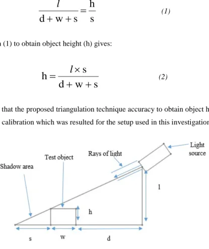
The proposed triangulation technique is based on the trigonometric relationships, the technique implies the determination of the height of an object from two known points as shown in Figure (5). A single light source is used to focus a narrow beam at an object to form, as possible, a parallel ray of light on the object. For the purpose of this work, orthographic light projection is needed, however it was approximated, and thus approximation errors within accepted range may result. The perpendicular distance between the light source and the base line is denoted by (l), while the distance between the object edge and the light source along the base line is denoted by (d), and knowing that (h), (w), and (s) represent the object height, width, and shadow length respectively. The relationship formulation of similar triangles could be stated as follows:
46
s
h
s
w
d
+
+
=
l
(1)Re-arranging equation (1) to obtain object height (h) gives:
s
w
d
s
h
+
+
×
=
l
(2)It is essential to know that the proposed triangulation technique accuracy to obtain object height depends mainly on the applied camera calibration which was resulted for the setup used in this investigation.
Figure 5: Principles of the triangulation technique
3.3.Image processing algorithm
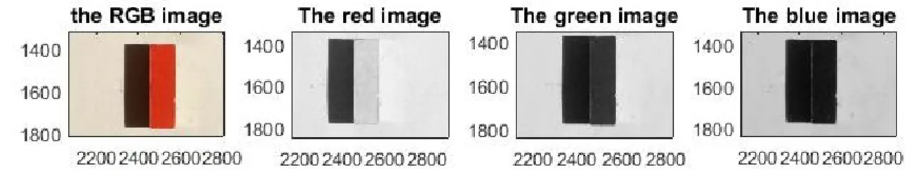
The aim of the image processing algorithms is to extract the coordinates of the pixels that constitute the objects attribute. These coordinates will be utilized by developed computer vision algorithms to measure the objects feature. The captured image consists mainly of three different areas see Figure (6):
(a) The background (relative to the object) platform area, where each pixel has high contrast (high gray level).
(b) The shadow area of the object, where each pixel has low contrast (low gray level). (c) The area of the object, where each pixel has median contrast (median gray level).
This different in areas cause difficulties when convert the image to binary, the simple threshold method is difficult to separate object from shadow and background. The captured image in converted into three matrix to reduce the algorithm operation time, easily separated the object, shadow and background, and results get more accurate in measurement as shown in the figure (6). Selected a suitable threshold value depending on the images histogram and convert images to binary. Images was pass through preprocessing and morphological operation to extract components that are useful in the representation and description of region shape. Using subtracting images to calculate object’s width and height and a morphological dilation and erosion see figure (7).
47
Figure 6: The captured image and converted to three matrix
Figure 7: Subtracting images (a) object with shadow (b) just object
The algorithm depends on input image of the object to be reconstructed, the image captured (from the top view) is of the test object, which is here a block gauge shown in Figure (8), the image was captured using a camera height of (300 mm) from the platform with focal length (18 mm) and without room ambient light, and using a light height of (625 mm) and a light distance from the object of (610 mm). The image is converted by thresholding depending on the histogram into binary image to enable the detection of the object features. Figure (9) shows the block gauge image using ambient lighting. Compute object with, length by special cod using MATLAB program and calculated height from triangulation method.
a) b)
48
Figure 9: Block gauge image using ambient lighting
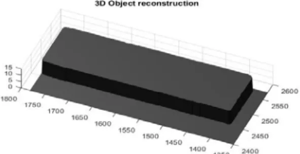
Both the object and shadow images are then subjected to further processing by computing local heights at each object pixel location to obtain 3D object reconstruction. Figure (10) show the result of 3D object reconstruction created based on the block gauge image shown in Figure (8) to provide the important information concerning the block gauge length and width respectively and on the block gauge shadow image shown in Figure (8.b) to provide the information concerning the shadow length that represent plug gauge height. Figure (10) present acceptable alternating gain and loss of information, with less than (0.07 mm) in difference between the peaks on the edges.
Figure 10: 3D block gauge component reconstruction
4.Experimental Results
Further experiments were performed on more complex surfaces and shapes, to assess and confirm the accuracy and the precision of this work approach to acquire 3D information and to prove the feasibility of the proposed approach for a variety of real objects.
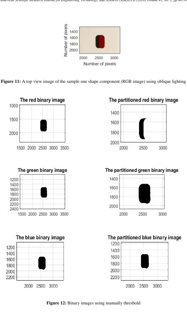
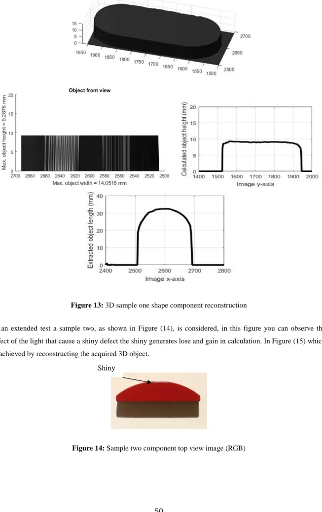
Sample one was used as shown in figure (11). Casting shadow unlike in projection of the real object related to insufficient illuminant angle, and to overcome this problem an investigation is conducted to select the maximum shadow value resulting from the experiments which is found to be equal to (113.6326 pixels). Otsu's method chooses a threshold that minimizes the intraclass variance of the threshold black and white pixels, so these method will not separate the background and foreground in binary images in an accuracy as a result. Figure (12) show a binary images with threshold selected manually. Figure (13) demonstrates the extracted and calculated component desired features as a 3D reconstruction view with acceptable dimensions and depth recovery in comparison with real sample one shape component.
49
Figure 11: A top view image of the sample one shape component (RGB image) using oblique lighting
Figure 12: Binary images using manually threshold
50
Figure 13: 3D sample one shape component reconstruction
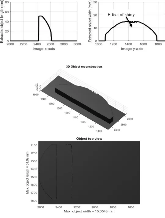
In an extended test asample two, as shown in Figure (14), is considered, in this figure you can observe the effect of the light that cause a shiny defect the shiny generates lose and gain in calculation. In Figure (15) which is achieved by reconstructing the acquired 3D object.
Figure 14: Sample two component top view image (RGB) Shiny
51
Figure 15: 3D sample two component reconstruction
5.System Verification
This section explains the calibration and the accuracy of the vision system used. In addition, the verification of the system accuracy and resulting errors are explained.
5.1.System calibration
A calibration process is very critical and an important factors in applications of computer and machine vision systems, images must be calibrated to achieve approximate dimensional image presentation. Camera calibration is the heart of this measuring system. All measurements performed on digital images refer to a pixel coordinate
52
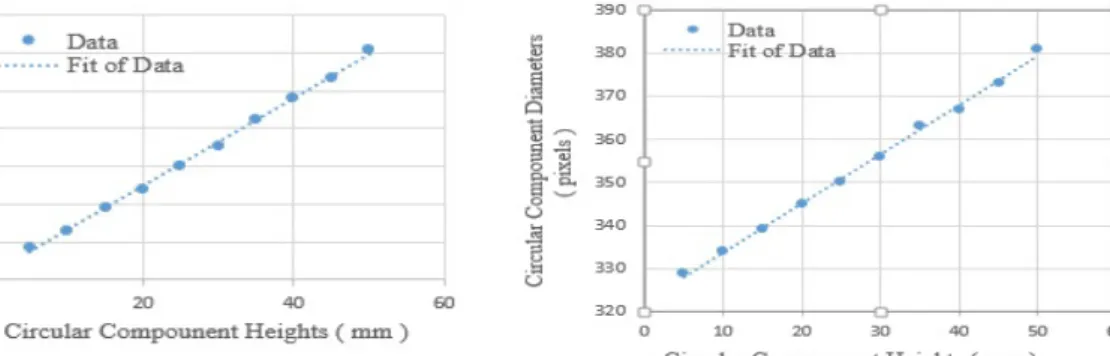
system, whereas real world measurements refer to the metric coordinate system, hence, calibration was made and results obtained over a number of experimental runs using the equipment setup described in section (2.1). The camera was calibrated using the top view of a circular standard shaft of (25 mm) diameter with deferent height from (5 – 50 mm) to achieve the scale factor. The diameter of the shaft in (pixel) is calculated using a program in MATLAB. A set of images is obtained using different object heights with stationary camera height (300 mm) and focal length (18 mm), the exposure time 1/25 sec., ISO speed 6400, resolution unit 2 and F-stop equal to F/5.6 these internal parameter of camera will be stationary for any image captured, each image is then processed to get the diameter of the circular component in pixel units. Figure (16) graphs the results needed for acquiring the mathematical presentation of the equation that best fits the acquired results, also show the components that used for calibrations.
C.F. or S.F. = 𝑎𝑎𝑎𝑎𝑎𝑎𝑎𝑎𝑎𝑎𝑎𝑎 (𝑠𝑠𝑎𝑎𝑎𝑎𝑠𝑠𝑠𝑠𝑎𝑎𝑠𝑠𝑠𝑠)𝑠𝑠𝑑𝑑𝑎𝑎𝑑𝑑𝑑𝑑𝑎𝑎𝑑𝑑𝑠𝑠
𝑠𝑠𝑛𝑛.𝑛𝑛𝑜𝑜 𝑝𝑝𝑑𝑑𝑝𝑝𝑑𝑑𝑎𝑎𝑠𝑠 𝑛𝑛𝑜𝑜 𝑎𝑎ℎ𝑑𝑑 𝑛𝑛𝑜𝑜𝑜𝑜𝑑𝑑𝑎𝑎𝑎𝑎 (3)
a) b)
Figure 16: The relation of circular component diameters and circular component heights and their linear fitting, a) for x-axis, b) for y-axis of the circulars c) circular components used
It is worth noting that due to the linear characteristic of obtained measurements, iterations are performed to find best equation that fits the data, where the best obtained mathematical relationship is:
y = 1.1915x + 320.53 for x-dia. (5)
y = 1.1406x + 322.33 for y-dia. (6)
Where (y) presents acquired entity diameter within the image in (pixel) units and (x) presents the object height in (mm) units.
53
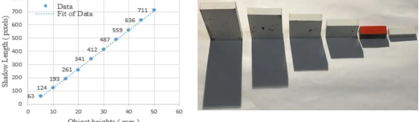
To evaluate the assumed case in which only parallel rays of light intercepts the object, a set of experimental tests were conducted. Camera height was positioned at (30 cm) and light source height and distance respectively (62.5 cm) (61.5 cm), however a number of objects having different object height were used. Figure (17) shows acquired results and components used to estimate there calibration equation.
a) b)
Figure 17: Results of shadow length and object heights and their linear fitting b) components used
Where linear relationship is obtained, hence to find any object height in (mm) units using its acquired shadow then the following expression is used:
y = 14.539x - 21.133 (7)
Where (y) representing the no. of pixels of object height that calculates in MATLAB by prepare a special program and (x) represent the object height in (mm) units.
5.2.System accuracy
The accuracy of the employed vision system can be affected by four factors the first factor is the size of the measured objects, the second factor is the size of the captured image, the third factor is the light used and distance of light from object, and finally distance of the object to camera and type of camera used. For the first factor, increasing the size of the measured object increases the pixel size, i.e. decreases the accuracy of measurement. For the second factor, increasing the size of the captured image decreases the pixel size, i.e. increases the accuracy of measurement and increases the processing time. For the third factors, the light affected on the object to be scanned and cause shiny that will effect on the threshold value and cause zigzag edge in binary image and this reflected on the dimension and reconstructed objects shaped. For the forth factors, if the camera moved away from the object the pixels will be decreases and vice versa. Figure (18) shows the relationship between the pixel size and both of the size of the captured image and the processing time. From the figure, it can be notice that the images with size of 4.2 Mp (2048*2048 pixels) can produce a resolution of 4 µm/pixel for major diameter in a reasonable processing time (3.85 sec.).
54
Figure 18: Relationship between the captured image size and both pixel size and processing time.
5.3.System verification
To verify the proposed vision system, an ISO mile-metric block gauge with nominal major dimensions equals to (9 mm ), (30 mm), and (10 mm) in width, length, and height respectively, and (9.0395 mm ), (30.0419 mm), and (10.0683 mm) in width, length, and height respectively was measured by the proposed vision system. The measurement process was performed by the proposed software, and all of the measurements were recorded. The features of the ISO mile-metric block gauge were calculated according to its basic geometry. Table (1) shows a comparison between the values of the object features for both the real objects and the measured features by the developed system. The differences between the real objects and measured features are listed in the same table.
Furthermore, from the conducted experiments, it is found that the proposed algorithm in this work is capable of making precise 3D reconstruction, surface, shape and measurements for a number of real objects in different shapes and with various changes in materials, heights, and sizes using their single top view image.
The results of the experiments using the block gage component indicate that the maximum difference between the real dimensions and calculated dimensions is less than (0.0683mm) which occurs in the height attribute set. Whereas the error (0.0876) that well be found in width attribute of the sample one component. Also, the maximum error in height attribute of the sample two reached to (0.0543).
Table 1: A comparison between the values of the attributes for both real objects and the attributes measured by the vision system (the maximum deviation value of each attribute set resulting of the test is recorded)
No. Object Name Attribute (MM) Verner Caliber Value Machine Vision Value E=|Verner - Machine| 1 Block gauge Width 9 9.0395 0.0395 Length 30 30.0419 0.0419 Height 10 10.0683 0.0683 2 Sample one Width 14.11 14.0516 0.0584 Length 32.3 32.3779 0.0779 Height 9.2 9.2876 0.0876 3 Sample two Width 15 15.0543 0.0543 Length 51 51.02 0.02 Height 13 13.006 0.006 0 5 10 15 20 0 2 4 6 8 10 12 0 2 4 6 8
P
ro
cessi
n
g
T
im
e
(sec.
)
P
ix
el
s S
iz
e
(µ
m)
Image Size (Miga Pixels)
55
6.ConclusionThe goal of computer vision is to extract useful information from image. In this work, eye-in-hand configuration was investigated to suit computer vision and image processing applications to reconstruct objects using inexpensive equipment as a new non-contact measurement system. Although the goal of 3D objects reconstructing from a single captured image is remain challenging problem, the suggested methodology succeeded to achieve close to real measurements of different object shapes and material. The novel application of this work by using shadow (to obtain objects height) in object reconstruction process helps to be faster, more intelligent and more inexpensive than the other proposed algorithms. The results concluded:
1. Camera calibration is the first step in this work.
2. The extracted features have errors caused by the fit the centre of lens of camera and object also it is planes.
3. The selection of threshold value is very critical, because it succeeded in distinguishing the object in the scene without any prior information about the object or the scene.
4. Thresholding value leads to loss of some of object information, so affecting the accuracy of the proposed method.
5. Using scanning program with MATLAB to compute number of pixels in two dimensions image and converted to millimeter units lead to measure the object attributes with very low error and low cost. 6. Results also showed that the system is applicable to handle different shape objects including those
having various changes in materials, colors, heights, and sizes.
7. These close to actual measurements were gained due to the well control of light, suitable selected image threshold value, and the careful setting of calibration.
8. It can be observed that the points close to the object boundary are more prone to false feature extraction than the points inside the object surface area due to the image quality and the selected value of image threshold.
The overall accuracy of the system was found to be (0.4539 mm) using the achieved setup and the adopted imaging hardware. The errors resulted can be easily modified in MATLAB to get perfect object. These erroneous points may have a cumulative effect on the feature attribute assignment process and therefore may affect the process of 3D objects re-construction.
References
[1] M. C. Martin, "Genetic programming for real world robot vision," in Intelligent Robots and Systems, 2002. IEEE/RSJ International Conference on, 2002, pp. 67-72.
[2] A. Zamirroshan, "DESIGNING SOFTWARE FOR 3D OBJECT MODELLING USING DIGITAL CLOSE RANGE PHOTOGRAMMETRY."
[3] D. Page, A. Koschan, S. Voisin, N. Ali, and M. Abidi, "3D CAD model generation of mechanical parts using coded-pattern projection and laser triangulation systems," Assembly Automation, vol. 25, pp.
56
230-238, 2005.[4] K. Peng, Y. Cao, Y. Wu, and Y. Xiao, "A new pixel matching method using the modulation of shadow areas in online 3D measurement," Optics and Lasers in Engineering, vol. 51, pp. 1078-1084, 2013.
[5] Z. Tian, D. Weng, Y. Wang, Y. Liu, and Y. Zhang, "Depth information extraction with an aperture-rotating camera," Optik-International Journal for Light and Electron Optics, vol. 125, pp. 4009-4013, 2014.
[6] N. Chotikakamthorn, "Near point light source location estimation from shadow edge correspondence," in Cybernetics and Intelligent Systems (CIS) and IEEE Conference on Robotics, Automation and Mechatronics (RAM), 2015 IEEE 7th International Conference on, 2015, pp. 30-35.
[7] J. Zavala, G. Gonzalez, E. Castillo, C. Isaza, and K. Anaya, "Three-dimensional Reconstruction of Objects Obtained by Two Orthogonal Cameras," IEEE Latin America Transactions, vol. 13, pp. 3162-3168, 2015.
[8] G. Peng, Z. Zhang, and W. Li, "Computer vision algorithm for measurement and inspection of O-rings," Measurement, vol. 94, pp. 828-836, 2016.
[9] Dr. Ali Abbar Khleif and Athraa M.Salih Ahmed, ''3D Object Modeling Using Eye on Hand Approach,'' Eng. and tech. journal, vol.34, part (A), No.3, 2016.
[10] G. Wang and J. Cheng, "Three-dimensional reconstruction of hybrid surfaces using perspective shape from shading," Optik-International Journal for Light and Electron Optics, vol. 127, pp. 7740-7751, 2016.
[11] E. Gadelmawla, "Computer vision algorithms for measurement and inspection of external screw threads," Measurement, vol. 100, pp. 36-49, 2017.
[12] A. A. Ahmed, M. K. Elbashir, and A. A. Osman, "Distance alert system using Stereo vision and feature extraction," in Communication, Control, Computing and Electronics Engineering (ICCCCEE), 2017 International Conference on, 2017, pp. 1-5.