Application Note
This document provides information to programmers to write optimal code for the MPC750, MPC7400, and
MPC7450 microprocessors that implement the PowerPC™ architecture, with particular emphasis on the MPC7450, which is significantly different from previous designs. The target audience includes performance-oriented writers of both compilers and hand-coded assembly.
This document is a companion to the PowerPC Compiler Writer’s Guide (CWG), with major updates for new
implementations not covered by that work; it is not a guide for making a basic PowerPC compiler work. For compiler guidelines, see the CWG. (However, many of the code sequences suggested in the CWG are no longer optimal, especially for the MPC7450.)
For details on the three different microprocessors and compiler guidelines, consult the following references: • MPC750 RISC Microprocessor Family User’s
Manual
• MPC7410 and MPC7400 RISC Microprocessor User’s Manual
• MPC7450 RISC Microprocessor Family User’s Manual
• The PowerPC Compiler Writer’s Guide (available on the IBM web site)
Contents
1 Terminology and Conventions . . . .2
2 Processor Overview . . . .4
3 Overview of Target Microprocessors . . . .7
4 MPC7450 Microprocessor Details . . . .16
5 Dispatch Considerations . . . .26
6 Issue Queue Considerations . . . .29
7 Completion Queue . . . .31
8 Numeric Execution Units . . . .32
9 FPU Considerations . . . .33
10 Memory Subsystem (MSS) . . . .42
11 Microprocessor Application to Optimal Code . . . .44
12 Optimized Code Sequences . . . .52
Appendix AMPC7450 Execution Latencies . . . .60
Appendix BRevision History . . . .75
MPC7450 RISC Microprocessor
Family Software Optimization Guide
Document Number: AN2203 Rev. 2, 06/2007
Table 1 lists the three main processors referenced in this document and their derivatives. The derivative list is not necessarily complete and is subject to change.
1
Terminology and Conventions
This section provides an alphabetical glossary of terms used in this document. Because of the differences in the MPC7450, many of these definitions differ slightly from those for previous processors that
implement the PowerPC architecture, particularly with respect to dispatch, issue, finishing, retirement, and write-back:
• Branch prediction—The process of guessing the direction or target of a branch. Branch direction prediction involves guessing whether a branch will be taken. Target prediction involves guessing the target address of a bclr branch. The PowerPC architecture defines a means for static branch prediction as part of the instruction encoding.
• Branch resolution—The determination of whether a branch prediction is correct. If it is, the instructions after the predicted branch that may have been speculatively executed can complete (see completion). If the prediction is incorrect, instructions on the mispredicted path and any results of speculative execution are purged from the pipeline and fetching continues from the correct path. • Complete—An instruction is in the complete stage after it executes and makes its results available for the next instruction (see finish). At the end of the complete stage, the instruction is retired from the completion queue (CQ). When an instruction completes, it is guaranteed that this instruction and all previous instructions can cause no exceptions.
• Dispatch—The dispatch stage decodes instructions supplied by the instruction queue, renames any source/target operands, determines to which issue queue each non-branch instruction is dispatched, and determines whether the required space is available in both that issue queue and the completion queue.
• Fall-through folding (branch fall-through)—Removal of a not-taken branch. On the MPC7450, not-taken branch instructions that do not update LR or CTR can be removed from the instruction stream if the branch instruction is in IQ3–IQ7.
• Fetch—The process of bringing instructions from memory (such as a cache or system memory) into the instruction queue.
• Finish—An executed instruction finishes by signaling the completion queue that execution is complete and results are available to subsequent instructions. For most execution units, finishing occurs at the end of the last cycle of execution; however, FPU, IU2, and VIU2 instructions finish at the end of a single-cycle finish stage after the last cycle of execution.
• Folding (branch folding)—The replacement of a branch instruction and any instructions along the not-taken path with target instructions when a branch is either taken or predicted as taken.
Table 1. Microarchitecture List
First Implementation Derivatives (Similar Devices)
MPC750 MPC740, MPC745, MPC755
MPC7400 MPC7410
• Issue—The pipeline stage reads source operands from rename registers and register files. This stage also assigns and routes instructions to the proper execution unit.
• Latency— The number of clock cycles necessary to execute an instruction and make the results of that execution available to subsequent instructions.
• Pipeline—In the context of instruction timing, refers to the interconnection of the stages. The events necessary to process an instruction are broken into several cycle-length tasks so work can be performed on several instructions simultaneously—analogous to an assembly line. As an instruction is processed, it passes from one stage to the next. When it does, the stage becomes available for the next instruction.
Although an individual instruction can take many cycles to make results available (see latency), pipelining makes it possible to overlap processing so that the throughput (number of instructions processed per cycle) is increased.
• Program order—The order of instructions in an executing program; more specifically, the original order in which program instructions are fetched into the instruction queue from the cache.
• Rename registers—Temporary buffers for holding results of instructions that have finished execution but have not completed.
• Reservation station—A buffer between the issue and execute stages that allows instructions to be issued even though the results of other instructions on which the issued instruction may depend are not available.
• Retirement—Removal of a completed instruction from the CQ.
• Speculative instruction—Any instruction that is currently behind an unresolved older branch. • Stage—An element in the pipeline where specific actions are performed, such as decoding an
instruction, performing an arithmetic operation, or writing back the results. Typically, the latency of a stage is one processor clock cycle. Some events, such as dispatch, writeback, and completion, happen instantaneously and may be thought to occur at the end of a stage.
An instruction can spend multiple cycles in one stage. For example, an integer multiply takes multiple cycles in the execute stage. When this occurs, subsequent instructions may stall.
An instruction can also occupy more than one stage simultaneously, especially in the sense that a stage can be viewed as a physical resource—for example, when instructions are dispatched they are assigned a place in the CQ at the same time they are passed to the issue queues.
• Stall—An instruction cannot proceed to the next stage.
• Superscalar—A superscalar processor can issue multiple instructions concurrently from a
conventional linear instruction stream. In a superscalar implementation, multiple instructions can be in the execute stage at the same time.
• Throughput—The number of instructions that are processed per cycle. For example, a series of
mulli instructions have a throughput of one instruction per clock cycle.
• Write-back—Write-back (in the context of instruction handling) occurs when a result is written into the architecture-defined registers (typically the GPRs, FPRs, and VRs). On the MPC7450, write-back occurs in the clock cycle after the completion stage. Results in the write-back buffer cannot be flushed. If an exception occurs, results from previous instructions must write back before the exception is taken.
2
Processor Overview
This section describes the high-level differences between the MPC750, the MPC7400, and the MPC7450. Also, it describes the pipeline differences in these three processors.
2.1
High-Level Differences
To achieve a higher frequency, the MPC7450 design reduces the number of logic levels per cycle, which extends the pipeline. More resources are added to reduce the effect of the pipeline length on performance. These pipeline length and resource changes can make an important difference in code scheduling. Table 2 describes high-level differences between MPC750, MPC7400, and MPC7450 processors.
Table 2. High-Level Differences
Microprocessor Feature MPC750 MPC7400 MPC7450
Basic Pipeline Functions
Logic inversions per cycle 28 28 18
Pipeline stages up to first execute 3 3 5
Minimum total pipeline length 4 4 7
Pipeline maximum instruction throughput 2 + 1 branch 2 + 1 branch 3 + 1 branch Pipeline Resources
Instruction queue size 6 6 12
Completion queue size 6 8 16
Rename register (integer, vector, FP) 6, N/A, 6 6, 6, 6 16, 16, 16
Branch Prediction Resources/Features
Branch prediction structures BTIC, BHT BTIC, BHT BTIC, BHT, LinkStack
BTIC size, associativity 64-entry, 4-way 64-entry, 4-way 128-entry, 4-way
BTIC instructions/entry 2 2 4
BHT size 512-entry 512-entry 2048-entry
Link stack depth N/A N/A 8
Unresolved branches supported 2 2 3
Branch taken penalty (BTIC hit) 0 0 1
Minimum branch mispredict penalty (cycles) 4 4 6
Available Execution Units Integer execution units 1 IU1, 1 IU1/IU2,
1 SRU, 1 LSU 1 IU1, 1 IU1/IU2, 1 SRU, 1 LSU 3 IU1, 1 IU2/SRU, 1 LSU
Floating-point execution units 1 double-precision FPU 1 double-precision FPU 1 double-precision FPU
Vector execution units N/A 2-issue to VPU and
VALU (VALU has VSIU, VCIU, VFPU subunits)
2-issue to any 2 vector units (VSIU,
Typical Execution Unit Latencies
Data cache load hit (integer, vector, float) 2, N/A, 2 2, 2, 2 3, 3, 4
IU1 (add, shift, rotate, logical) 1 1 1
IU2: multiply (32-bit) 6 6 4
IU2: divide 19 19 23
FPU: single (add, mul, madd) 3 3 5
FPU: single (divide) 17 17 21
FPU: double (add) 3 3 5
FPU: double (mul, madd) 4 3 5
FPU: double (divide) 31 31 35
VSIU N/A 1 1
VCIU N/A 3 4
VFPU N/A 4 4
VPU N/A 1 2
L1 Instruction Cache/Data Cache Features
L1 cache size (instruction, data) 32-Kbyte, 32-Kbyte
L1 cache associativity (instruction, data) 8-way, 8-way
L1 cache line size 32 bytes
L1 cache replacement algorithm Pseudo-LRU
Number of outstanding data cache misses (load/store)
1 (load or store) 8 (any combination load/store)
5 load/1 store
Additional On-Chip Cache Features
Additional on-chip cache level None None L2
Additional on-chip cache size N/A N/A 256-Kbyte
Additional on-chip cache associativity N/A N/A 8-way
Additional on-chip cache line size N/A N/A 64 bytes
(2 sectors per line)
Additional on-chip cache replacement algorithm N/A N/A Pseudo-random
Off-Chip Cache Support
Off-chip cache level L2 L3
Off-chip cache size 256-Kbyte, 512-Kbyte,
1-Mbyte
512-Kbyte, 1-Mbyte, 2-Mbyte
1-Mbyte, 2-Mbyte
Off-chip cache associativity 2-way 2-way 8-way
Off-chip cache line size/sectors per line 64B/2, 64B/2, 128B/4 32B/1, 64B/2, 128B/4 64B/2, 128B/4
Off-chip cache replacement algorithm FIFO FIFO Pseudo-random
Table 2. High-Level Differences (continued)
2.2
Pipeline Differences
The MPC7450 instruction pipeline differs significantly from the MPC750 and MPC7400 pipelines. Figure 1 shows the basic pipeline of the MPC750/MPC7400 processors.
Figure 1. MPC750 and MPC7400 Pipeline Diagram
Table 3 briefly explains the pipeline stages.
Figure 2 shows the basic pipeline of the MPC7450 processor, and Table 4 briefly explains the stages.
Figure 2. MPC7450 Pipeline Diagram
Table 4 briefly explains the MPC7450 pipeline stages.
Table 3. MPC750/MPC7400 Pipeline Stages
Pipeline Stage Abbreviation Comment
Fetch F Read from instruction cache
Branch execution BE Execute branch and redirect fetch if needed
Dispatch D Decode, dispatch to execution units, assigned to rename register, register file read Execute E, E0, E1, ... Instruction execution and completion
Write-back WB Architectural update
F
E0 BE
Branch IU1 LSU
WB E1 WB E D F F D
Branch IU1 LSU
BE F1 F2 I E F1 F2 D I E1 E2 F2 F1 D C C E0 WB WB
The MPC7450 pipeline is longer than the MPC750/MPC7400 pipeline, particularly in the primary load execution part of the pipeline (3 cycles versis 2 cycles). Faster processor performance often requires designs to operate at higher clock speeds. Clock speed is inversely related to the work performance of the processor. Therefore, higher clock speeds imply less work to be performed per cycle, which necessitates longer pipelines. Also, increased density of the transistors on the chip has enabled the addition of
sophisticated branch-prediction hardware, additional processor resources, and out-of-order execution capability. This industry trend should continue for at least one more microprocessor generation. The longer pipelines yield a processor more sensitive to code selection and ordering. Because hardware can add additional resources and out-of-order processing ability to reduce this sensitivity, the hardware and the software must work together to achieve optimal performance.
3
Overview of Target Microprocessors
This section provides a high-level overview of the three target microprocessors, with first-order details that are useful in developing a compiler model of the microprocessor.
3.1
MPC750 Microprocessor
Figure 3 shows a functional block diagram of the MPC750.
Table 4. MPC7450 Pipeline Stages
Pipeline Stage Abbreviation Comment
Fetch1 F1 First stage of reading from instruction cache Fetch2 F2 Second stage of reading from instruction cache Branch execute BE Execute branch and redirect fetch if needed
Dispatch D Decode, dispatch to IQs, assigned to rename register Issue I Issue to execution units, register file read
Execute E, E0, E1, ... Instruction execution
Completion C Instruction completion
Figure 3. MPC750 Microprocessor Block Diagram A d di ti on a l F e a tur e s • T im e B a s e Co u n te r/ De c re m e n te r • C loc k Mul tip lie r • J T AG /C O P In te rf a c e • T h e rma l/ P o w e r Ma na ge me nt • P e rf or m a nc e Mo ni to r + + F et cher Bran ch P ro cessi n g BT IC 64-E n tr y + x ÷ FP S C R CR FP S C R L2C R CT R LR BH T Dat a M M U In st ru ct io n M M U Not in t he M P C740 EA PA + x ÷ In st ru ct io n Un it Un it In st ru ct ion Q ueue (6 -W or d) 2 I ns tr uc tions Res er vat ion S tat io n R es er vat ion S tat io n R es er vat ion S tat ion In te ge r U n it 1 S yst em Reg ist er Un it Dis pat ch Unit 64-B it (2 In st ru ct io ns ) SR s ITL B (S hadow) IB A T Arr ay 32-K b yt e I C ac he T ags 128-B it (4 In st ru ct io ns ) Res er vat ion S tat ion 32-B it F loa ti n g -P oi nt Un it R e name B u ffer s (6 ) FP R Fi le 32-B it 64-B it 64-B it R e se rv at io n S tat io n (2 -En try ) Loa d/ S tor e U n it (E A Calc ulat ion) S tor e Q ueue GP R F ile R enam e B uf fer s (6 ) 32-B it SR s (O riginal) DTLB DB A T A rra y 64-B it Co mp le ti o n Un it Reor der B uf fer (6 -E nt ry) T ags 32 -K by te D Cac h e 60x Bu s In te rf ac e Un it In st ru ct ion F et ch Q ueue L1 Cas tout Q ueue D at a Load Q ueue L2 C o nt ro lle r L2 T ags L 2 Bu s In te rf ac e Un it L2 Cas tout Q u eue 32-B it A ddr es s B us 64 -Bi t D at a Bu s 17-B it L2 A ddr es s B us 64-B it L2 Dat a B u s In te ge r U n it 2 64-B it
Instructions are fetched from the instruction cache and placed into a six-entry IQ. When the fetch pipeline is fully utilized, as many as four instructions can be fetched to the IQ during each clock cycle, subject to cache block wrap restrictions.
3.1.1
Dispatch
The bottom two IQ entries are available for dispatch, which involves the following operations:
• Renaming—Six rename registers are available for integer operation and six more are available for floating-point operations.
• Dispatching—A reservation station must be available for the correct execution unit. • CQ check—An entry must be available in the six-entry CQ.
• Branch check—A branch instruction must have executed before being dispatched. Section 3.1.4, “Branches,” provides additional information.
3.1.2
Execution
An instruction in the bottom of a reservation station is available for execution. Execution involves the following operations:
• Busy check—The unit must be available. For example, some units are not fully pipelined. • Operand check—All source operands must be available before any execution can start.
• Serialization check—If the instruction is execution serialized, it must wait to become the oldest instruction in the machine (bottom of the CQ entry) before it can start execution.
3.1.3
Completion
The bottom two CQ entries are available for completion, which involves the following operations: • Finish check—Only instructions that have finished or are in the last stage of execution are eligible
for finishing.
• Rename check—The MPC750 can write back only two rename registers per cycle. Some
instructions, such as a load-with-update, have multiple renamed targets. If a load-with-update and an add instruction are in the bottom two CQ entries, the add cannot complete because the load-with-update already requires two rename-register-writeback slots for the subsequent cycle.
NOTE
In the MPC750, execution and completion can occur simultaneously for single-cycle execution instructions.
3.1.4
Branches
Branches are handled differently from other instructions. Branch instructions must be executed by the branch unit before they can be dispatched. The BPU searches the six-entry IQ for the oldest unexecuted branch and executes it. If the branch instruction does not update the architectural state by setting the link or count register, it is eligible for folding. In branch execution, the instruction is folded immediately if the branch is taken. In this case, folding removes the branch instruction from the IQ, so the branch instruction
does not reach the dispatcher. If the branch is not taken, the dispatcher must dispatch the branch. However, the branch is not allocated in the CQ, so no completion is required either.
If the branch is either b or bc, a taken branch can get instructions from the BTIC. The BTIC lookup is automatically performed based on the instruction address of the executing branch, and produces instructions starting at the branch target address. The BTIC supplies two instructions for that cycle, as opposed to the normal four from the instruction cache. Indirect branches, such as bcctr or bclr, do not get instructions from the BTIC. Thus, a taken branch incurs a one-cycle fetch bubble when it executes.
3.1.5
MPC750 Compiler Model
A good compiler scheduling model for the MPC750 includes the two-instruction-per-clock-cycle dispatch limitation, a base model of the CQ with a maximum of six instructions with
two-instruction-per-clock-cycle completion limitation, and execution units—SRU, IU1, IU2, FPU, and LSU with typical unit execution latencies as given in Table 1.
A full model incorporates full table-driven latency/throughput/serialization specifications given instruction by instruction in Appendix A, “MPC7450 Execution Latencies.” The notion of reservation stations (particularly, the second LSU reservation station) should be added.Rename registers limitations for the GPRs are also needed to allow more accurate modeling of the load/store-with-update instructions.
3.2
MPC7400 Microprocessor
The MPC7400 microprocessor is similar to the MPC750 microprocessor. The primary differences include the following attributes:
• Eight-entry CQ (although rename registers are still limited to six)
• Vector units (and instructions), which implement the Altivec extensions to the PowerPC architecture
• Better latency and pipelining on double-precision floating-point operations • Increased pipelining of load/store misses in the LSU
Figure 4 shows a functional block diagram of the MPC7400.
3.2.1
Vector Unit
The MPC7400 can dispatch two vector instructions per cycle: one to the VPU and one to the VALU. The VPU is a single-cycle execution unit unlike the VALU that has three independent subunits, each with different latencies, as follows:
• The VSIU subunit handles simple integer and logical operations with single-cycle latency per instruction.
• The VCIU handles complex integer instructions (mostly multiplies) with a latency of three clocks and a throughput of one instruction per cycle.
• The VFPU subunit handles vector floating-point instructions with a latency of four clocks and a throughput of one instruction per cycle.
Figure 4. MPC7400 Microprocessor Block Diagram + + F et cher Bran ch P ro cessi n g BT IC (64-E nt ry ) + x ÷ FP S C R VS C R FP S C R L2CR CT R LR PA EA + x ÷ In st ru ct io n Un it Un it In st ru ct io n Q ue ue (6 -W o rd ) 2 I ns tr uc tio n s Res er vat ion In te g er S yst em Dis pat ch Unit 64-B it ( 2 I ns tr uc tions ) 128-B it (4 In st ru ct ions ) 32 -B it F loa ti ng-P o in t U n it 32 -B it 64-B it Res er vat ion Lo ad /S to re U n it (E A Calc ul at ion) F in is hed 32-B it Co mp le ti o n Un it Com p le tion Q ue ue (8 -E nt ry) T ags 32-K by te D Cac he M emo ry S u b syst em In st ru ct io n Dat a Reload L2 C o nt ro lle r L2 T ags B u s I n te rf ace U n it L2 Ca s to u t 32-B it A d dr es s B us 64 -Bi t D at a Bu s 18-B it L2 A ddr es s B us 64-B it L2 Dat a B us In te g er St at io n Res er vat io n St at io n Res er vat ion St a tio n Reg ist er U n it U n it 1 U ni t 2 Res er vat ion St a tio n FP R Fi le 6 Renam e Bu ffe rs S tat ion ( 2-E nt ry ) GP R F ile 6 Renam e Bu ffe rs VC IU V ect o r V ect o r A L U R es er vat ion St at io n Res er vat ion St a tio n Pe rm u te VR F ile 6 Renam e Bu ffe rs Un it 64-B it R eload T able VS IU VF PU 128-B it 128-B it A bilit y t o c om plet e u p Com pl et ed In st ru ct io n M M U SR s (S hado w) 1 28-E n tr y IB A T A rra y IT LB BH T (512-E nt ry ) L2 M is s Da ta T rans ac tion T able Ta g s 32-K by te I C ac h e D at a Reload Queue In st ru ct io n Reload Q ueu e to tw o ins tr uc tions per c loc k Dat a M M U SR s (O riginal) 1 28-E n tr y DB A T A rra y DT LB Loa d F old L1 S tor es S tor es O pe rat ions L2 Dat a T rans ac tion Ve ct or T ouc h Q ueue A ddi ti on a l Fe a tu re s • T im e B a s e C o u n te r/ D e c re m e n te r • C loc k M u lt ip lier • J T AG /C O P In te rf a c e • T h e rm a l/ P o w e r Ma na ge m e n t • P e rf or m a n c e M o ni to r
3.2.2
MPC7400 Compiler Model
A good compiler scheduling model for the MPC7400 includes the dispatch limitations of two instructions per clock, a base model of the CQ with a maximum of eight instructions, the completion limitation of two instructions per clock, and the execution units—SRU, IU1, IU2, FPU, VPU, VALU (VSIU, VCIU, VFPU), and LSU with typical execution unit latencies as given in Appendix A, “MPC7450 Execution Latencies.” A full model incorporates full table-driven latency/throughput/serialization specifications given
instruction by instruction in Appendix A, “MPC7450 Execution Latencies.” The concept of reservation stations (especially the second LSU reservation station) should be added. The rename registers limitations are much more important than in the MPC750, since the number of rename registers (six) does not match the number of completion entries (eight).
3.3
MPC7450 Microprocessor
Different resource sizes, issue queues, and the splitting of the completion and execution stages are the main differences between the MPC7450 and the MPC750/MPC7400 models. Also, the MPC7450 can dispatch up to three instructions per cycle (compared to two on the MPC7400) and can complete a maximum of three instructions per cycle (compared to two on the MPC7400).
With the addition of extra integer units, the MPC7450 has more integer computing capacity available for scheduling. The MPC7450 has three single-cycle IUs (IU1a, IU1b, IU1c) that execute all integer
(fixed-point) instructions (addition, subtraction, logical operations—AND, OR, shift, and rotate) except multiply, divide, and move to/from special-purpose register instructions. Note that all IU1 instructions execute in one cycle, except for some instructions like tw[i] and sraw[i][.], which take two. In addition, it has one multiple-cycle IU (IU2) that executes miscellaneous instructions including the CR logical operations, integer multiplication and division instructions, and move to/from special-purpose register instructions. The issue requirements for the vector subunits are also improved which is described in detail in Section 6.2, “Vector Issue Queue (VIQ).”
The longer pipeline of the MPC7450 is more sensitive to branch mispredictions. Taken branches of MPC7450 cause a single-cycle fetch bubble, whereas most taken branches on the MPC750/MPC7400 were nearly free. The MPC7450 also changes the load-use latency, which is critical to adjust to achieve best performance on many applications. Also, serialized instructions are more costly in terms of
performance on this microprocessor.
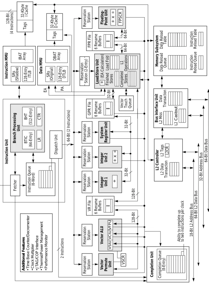
Figure 5. MPC7450 Microprocessor Block Diagram + In te g er R es erv at ion St at io n Uni t 2 + Int ege r Re se rv at io n St at ion Un it 2 + + x ÷ FP S C R FP S C R PA + x ÷ Ins tru c ti o n Uni t In st ruc tio n Q ueue (12 -W ord) 3 I ns truc tions Re se rv at io n In te g e r 128-B it (4 I n st ruc tio ns ) 32-Bi t F loa ti ng-Po in t U n it 64 -Bit Re se rv ati o n Loa d/S tore U n it (E A C al cul at io n) F inis h ed 32 -Bit Com pl e ti on Uni t C om plet ion Queue (16 -Ent ry ) Ta g s 32-Kb yt e D C a ch e L 3 C ach e C o n tr o ll er S yst em Bu s In te rf ace 36-B it Add res s Bus 6 4-Bit D at a Bus 18-Bit 64-Bit D at a In te g er St at ions ( 2) R es erv at ion St at io n R es erv at ion S tat ions (2) FP R Fi le 16 R e nam e Buf fe rs S tat io ns ( 2 -E nt ry ) GPR F ile 16 R enam e B uffe rs R es e rv at io n St at ion VR F ile 16 R ena m e Bu ffe rs 64 -Bit 128 -Bit 12 8-Bit C om ple te s up t o t hree ins tr uc tions per c lo ck c yc le Co mp le te d In st ru ct io n M M U SR s (S ha dow ) 1 28-E n tr y IBAT Array IT L B T ags 32-K by te I C a ch e St ores St ores Lo ad M is s Vec to r T ouc h Qu eue (3 ) VI Q F IQ B ran ch P ro ces si n g U n it CT R LR BT IC (128 -Ent ry ) BH T (2 048-Ent ry ) F e tc her GI Q (6 -Ent ry /3 -I ss u e) (4-E nt ry /2 -I ss ue) (2-Ent ry /1 -I ss ue) Di sp at ch Un it 2 56-K b y te U n if ie d L 2 C ach e/ C ach e C o n tr o ller D a ta MMU SR s (O rigina l) 128-E n tr y D BAT Array DT L B V ec tor T ou ch E ngi ne 32-Bi t EA L 1 C as tout St a tus L 2 Sto re Qu e u e (L 2SQ ) E xt ernal SR AM L3C R (8-B it Pari ty ) A ddres s Vecto r FP U R es erv at ion St at io n R es erv at ion St a tio n R es erv at io n St at ion Ve cto r In te g e r Un it 1 V ecto r Int ege r Un it 2 Vect o r Per mu te Un it Lin e St a tus Ta g s B us A ccu mu la to r Ta g s Bloc k 0 (32-By te ) St at u s Bloc k 1 (32 -By te ) B loc k 0/ 1 L ine Me m o ry S u bs y st em L1 L oad Queu e ( LLQ) L1 Load M is s (5) C ac h eable St ore In st ruc tion F et ch ( 2) R eques t (1) L 1 S erv ic e Q u eu es Snoop Pu sh / In te rv en tio ns L1 St ore Queu e L1 C as tou ts Pus h Ca st ou t Que ue Bus St ore Qu eue L2 Pr ef e tc h (3) Bus A cc um ulat or (1 or 2 M by te ) (LSQ ) L1 Pus h (4) (9) Un it 2 U n it 1 + X A d dit iona l Fe a tur e s • T im e B a s e C o u n te r/ D e c re m e n te r • C loc k M u lt ip lier • J T AG /C O P In te rf a c e • T h er ma l/ P o w e r Man a g e me nt • P e rf or ma nc e Mon it o r
3.3.1
Dispatch
The bottom three IQ entries are available for dispatch, which involves the following:
• Renaming—16 rename registers are available for each of the integer, floating-point, and vector operations.
• Dispatching—Available issue queue entries must be available for each dispatched instruction. • CQ check—An entry must be available in the 16-entry CQ.
• Branch check—A branch instruction must execute before it is dispatched. Section 3.3.8, “Branches,” provides more information on branching.
3.3.2
Issue Queues
Each issue queue handles issuing slightly differently and is described separately as follows.
3.3.3
General-Purpose Issue Queue
The six-entry general-purpose issue queue (GIQ in Figure 5) handles integer instructions, including all load/store instructions. The GIQ accepts as many as three instructions from the dispatch unit each cycle. All IU1s, IU2, and LSU instructions (including floating-point and AltiVec loads and stores) are dispatched to the GIQ. Instructions can be issued out-of-order from the bottom three GIQ entries (GIQ2–GIQ0). An instruction in GIQ1 destined to one of the IU1s does not have to wait for an instruction stalled in GIQ0 that is behind a long-latency integer divide instruction in the IU2. The primary check is that a reservation station must be available.
3.3.4
Floating-Point Issue Queue
The two-entry floating-point issue queue (FIQ) can accept one dispatched instruction per cycle for the FPU, and if an FPU reservation station is available, it can also issue one instruction from the bottom FIQ entry.
3.3.5
Vector Issue Queue
The four-entry vector issue queue (VIQ) accepts as many as two vector instructions from the dispatch unit each cycle. All AltiVec instructions (other than load, store, and vector touch instructions) are dispatched to the VIQ. The bottom two entries are allowed to issue as many as two instructions to the four AltiVec execution unit’s reservation stations, but unlike the GIQ, instructions in the VIQ cannot be issued out of order. The primary check determines if a reservation station is available.
NOTE
The VIQ can issue to any two vector units, unlike the MPC7400. For example, the MPC7450 can issue to the VSIU and VCIU simultaneously, whereas the MPC7400 allows pairing between the VPU and one of the other three VALU subunits.
3.3.6
Execution
The instruction in the bottom of the reservation station is available for execution. Execution involves the following:
• Busy check—The unit must not be busy. For example, some units are not fully pipelined and so cannot accept a new instruction on every clock.
• Operand check—All source operands must be available before any execution can start.
• Serialization check—If the instruction is execution serialized, it must wait to become the oldest instruction in the machine (bottom of the CQ entry) before it can start execution.
The MPC7450 has two more IUs than the MPC750/MPC7400. However, the integer unit capabilities have changed slightly from the MPC750/MPC7400 to the MPC7450, as shown in Table 5. Appendix A, “MPC7450 Execution Latencies,” compares latencies between MPC750, MPC7400, and MPC7450 for various instructions.
3.3.7
Completion
The bottom three CQ entries are available for retiring instructions. Completion involves the following operations:
• Finish check—Only instructions that finish can complete (except store instructions, which finish and complete simultaneously to allow pipelining).
• Rename check—An MPC7450 can write back only three rename registers per cycle. Some instructions, such as load-with-update, have multiple renamed targets. If a load-with-update is followed by two adds, only the load-with-update and the first add can complete at the same time (although all three instructions are finished executing). The load-with-update requires two of the three rename-register-writeback resources. Due to this resource constraint, the second add waits until the second cycle is completed.
3.3.8
Branches
Branches are handled differently from other instructions. Branch instructions must be executed by the branch unit before they can be dispatched. The BPU searches the bottom eight entries of the IQ for the oldest unexecuted branch and executes it. A branch instruction is eligible for folding if it does not update the architectural state by setting the link or count register. In branch execution, the instruction is folded immediately if the branch is taken. In this case, folding removes the branch instruction from the IQ, so the branch instruction does not reach the dispatcher. If the branch is not taken, the dispatcher must dispatch the branch, and the branch is placed in the CQ.
Table 5. MPC750/MPC7400 vs. MPC7450 Integer Unit Breakdown
Instruction Class MPC750/MPC7400 MPC7450
add, subtract, logical, shift/rotate IU1 or IU2 IU1 (any of 3)
mul, div IU2 IU2
NOTE
Note that in the MPC750, the dispatched (fall-through) foldable branches are not allocated in the CQ.
If the branch is either b or bc, a taken branch can get instructions from the BTIC. The BTIC lookup is automatically performed based on the instruction address of the executing branch and produces
instructions starting at the branch target address. Taken branches have a minimum one-cycle fetch bubble, since the BTIC supplies four instructions on the following cycle. Indirect branches such as bcctr or bclr do not get instructions from the BTIC. Thus, taken branches incur a two-cycle fetch bubble when they execute. From a code performance point of view, the need for biasing the branch to be fall-through has increased to avoid the 1- or 2-cycle fetch bubble of a taken branch. The longer pipeline makes the MPC7450 more sensitive to branch misprediction than earlier designs.
3.3.9
MPC7450 Compiler Model
A good scheduling model for the MPC7450 should take into account the dispatch limitations of the three instructions per cycle, the 16-entry CQ’s completion limitation of three instructions per cycle, and the various execution units with the latencies discussed earlier.
A full model would also incorporate the full table-driven latency/throughput/serialization specifications for each instruction listed in Appendix A, “MPC7450 Execution Latencies.” The usage and availability of reservation stations and rename registers should also be incorporated. Finally, attention should be given to the issue limitations of the various issue queues—for example, it is important to note that AltiVec instructions must be issued in-order out of the vector issue queue. This means that a few poorly scheduled instructions can potentially stall the entire vector unit for many cycles.
4
MPC7450 Microprocessor Details
This section describes many architectural details of the MPC7450 and gives examples of the pipeline behavior. These attributes are also described in the MPC7450 RISC Microprocessor Family User’s Manual.
4.1
Fetch/Branch Considerations
The following is a list of branch instructions and the resources required to avoid stalling the fetch unit in the course of branch resolution:
• The bclr instruction requires LR availability for resolution. However, it uses the link stack to predict the target address in order to avoid stalling the fetch unit.
• The bcctr instruction requires CTR availability.
• The branch conditional on counter decrement and the CR condition require CTR availability, or the CR condition must be false.
• A fourth conditional branch instruction cannot be executed following three unresolved predicted branch instructions.
4.2
Fetching
Branches that target an instruction at or near the end of a cache block can cause instruction supply problems. Consider a tight loop branch where the loop entry point is the last word of the cache block, and the loop contains a total of four instructions (including the branch). For this code, any MPC750/MPC7400 class machine needs at least two cycles to fetch the four instructions, because the cache block boundary breaks the fetch group into two groups of accesses. For the MPC750/MPC7400, realigning this loop to not cross the cache block boundary significantly increases the instruction supply.
Additionally, on the MPC7450 this tight loop encounters the branch-taken bubble problem. That is, the BTIC supplies instructions one cycle after the branch executes. For the instructions in the cache block crossing case, four instructions are fetched every three cycles. Aligning instructions to be within a cache block increases the number of instructions fetched to four every two cycles. For loops with more
instructions, this branch-taken bubble overhead can be better amortized or in some cases can disappear (because the branch is executed early and the bubble disappears by the time the instructions reach the dispatch point). One way to increase the number of instructions per branch is software loop unrolling.
NOTE
The BTIC on all MPC750/MPC7400/MPC7450 microprocessors contains targets for only b and bc branches. Indirect branches (bcctr and bclr) must go to the instruction cache for instructions, which incurs an additional cycle of fetch latency (another branch-taken bubble).
In future generations of these high performance microprocessors, expect a further bias—instruction fetch groupings that do not cross quad-word boundaries are preferable. In particular, this means that branch targets should be biased to be the first instruction in a quad word (instruction address = 0xxxxx_xxx0) when optimizing for performance (as opposed to code footprint).
4.2.1
Fetch Alignment Example
The following code loop is a simple array accumulation operation.
xxxxxx18 loop: lwzu r10,0x4(R9)
xxxxxx1C add r11,r11,r10
xxxxxx20 bdnz loop
The lwzu and add are the last two instructions in one cache block, and the bdnz is the first instruction in the next. In this example, the fetch supply is the primary restriction. Table 6 assumes instruction cache and BTIC hits. The lwzu/add of the second iteration are available for dispatch in cycle 3, as a result of a BTIC hit for the bdnz executed in cycle 1. The bdnz of the second iteration is available in the IQ one cycle later (cycle 4) because the cache block break forced a fetch from the instruction cache. Overall, the loop is limited to one iteration for every three cycles.
Table 6. MPC7450 Fetch Alignment Example
Instruction 0 1 2 3 4 5 6 7 8 9 10 11
lwzu (1) D I E0 E1 E2 C
add (1) D I — — — E C
Performance can be increased if the loop is aligned so that all three instructions are in the same cache block, as in the following example.
xxxxxx00 loop: lwzu r10,0x4(r9)
xxxxxx04 add r11,r11,r10
xxxxxx08 bdnz loop
The fact that the loop fits in the same cache block allows the BTIC entry to provide all three instructions. Table 7 shows pipelined execution results (again assuming BTIC and instruction cache hits). While fetch supply is still a bottleneck, it is improved by proper alignment. The loop is now limited to one iteration every two cycles, increasing performance by 50 percent.
Loop unrolling and vectorization can further increase performance. These are described in Section 11.4.3, “Loop Unrolling for Long Pipelines,” and Section 11.4.4, “Vectorization.”
4.2.2
Branch-Taken Bubble Example
The following code shows how favoring taken branches affects fetch supply.
xxxxxx00 lwz r10,0x4(r9) xxxxxx04 cmpi 4,r10,0x0 xxxxxx08 bne 4, targ lwzu (2) D I E0 E1 E2 C add (2) D I — — — E C bdnz (2) F1 F2 BE D — — — C lwzu (3) D I E0 E1 E2 C add (3) D I — — — E bdnz (3) F1 F2 BE D — — —
Table 7. MPC7450 Loop Example—Three Iterations
Instruction 0 1 2 3 4 5 6 7 8 9 lwzu (1) D I E0 E1 E2 C add (1) D I — — — E C bdnz (1) BE D — — — — C lwzu (2) D I E0 E1 E2 C add (2) D I — — — E C bdnz (2) BE D — — — — C lwzu (3) D I E0 E1 E2 C add (3) D I — — — E bdnz (3) BE D — — — —
Table 6. MPC7450 Fetch Alignment Example
xxxxxx0C stw r11,0x4(r9)
xxxxxx10 targ add (next basic block)
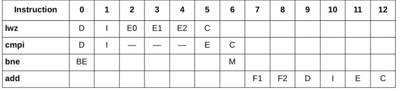
This example assumes the bne is usually taken (that is, most of the data in the array is non-zero). Table 8 assumes correct prediction of the bne, and cache and BTIC hits.
Rearranging the code as follows improves the fetch supply.
xxxxxx00 lwz r10,0x4(r9)
xxxxxx04 cmpi 4,r10,0x0
xxxxxx08 beq 4,targ
xxxxxx0C targ2 add (next basic block)
...
yyyyyy00 targ stw r11,0x4(r9)
yyyyyy04 b targ2
Using the same assumptions as before, Table 9 shows the performance improvement. Note that the first instruction of the next basic block (add) completes in the same cycle as before. However, by avoiding the branch-taken bubble (because the branch is usually not taken), it also dispatches one cycle earlier, so that the next basic block begins executing one cycle sooner.
4.3
Branch Conditionals
The cost of mispredictions increases with pipeline length. The following section shows common problems and suggests how to minimize them.
4.3.1
Branch Mispredict Example
Table 10 uses the same code as the two previous examples but assumes that the bne mispredicts. The compare executes in cycle 5, which means the branch mispredicts in cycle 6 and the fetch pipeline restarts at that correct target for the add in cycle 7. This particular mispredict effectively costs seven cycles (add dispatches in cycle 2 in Table 8 and in cycle 9 in Table 10).
Table 8. Branch-Taken Bubble Example
Instruction 0 1 2 3 4 5 6
lwz D I E0 E1 E2 C
cmpi D I — — — E C
bne BE
add D I E — C
Table 9. Eliminating the Branch-Taken Bubble
Instruction 0 1 2 3 4 5 6
lwz D I E0 E1 E2 C
cmpi D I — — — E C
beq BE D — — — — C
4.3.2
Branch Loop Example
CTR should be used whenever possible for branch loops, especially for tight inner loops. After the CTR is loaded (using mtctr), a branch dependent on the CTR requires no directional prediction in any of the MPC750/MPC7400 devices. Additionally, loop termination conditions are always predicted correctly, which is not so with the normal branch predictor.
xxxxxx18 outer_loop:addi. r6,r6,#FFFF xxxxxx1C cmpi 1,r6,#0 xxxxxx20 inner_loop:addic. r7,r7,#FFFF xxxxxx24 lwzu r10,0x4(r9) xxxxxx28 add r11,r11,r10 xxxxxx2C bne inner_loop xxxxxx30 stwu r11,0x4(r8) xxxxxx34 xor r11,r11,r11 xxxxxx38 ori r7,r0,#4 xxxxxx3C bne cr1,outer_loop
For the example, assume the inner loop executes four times per outer iteration. On a MPC7450 and also on MPC750/MPC7400 microprocessors, inner loop termination is always mispredicted because the branch predictor learns to predict the inner bne as taken, which is wrong every fourth time. Table 11 shows that the misprediction causes the outer loop code to be dispatched in cycle 13. If the branch had been correctly predicted as not taken, these instructions would have dispatched five cycles earlier in cycle 8. Table 11 shows this example transformed when using CTR for the inner loop.
Table 10. Misprediction Example
Instruction 0 1 2 3 4 5 6 7 8 9 10 11 12
lwz D I E0 E1 E2 C
cmpi D I — — — E C
bne BE M
The following code uses the CTR, which shortens the loop because the compare test (done by the addic. at xxxxxx20 in the previous code example) is combined into the bdnz branch. Note that in the previous example, the outer loop required an addi/cmpi sequence to save the compare results into CRF1, rather than an addic., since the inner loop used CRF0. In the example below, since the inner loop no longer uses CRF0, the outer loop compare code can be simplified to just an addic. instruction.
xxxxxx1C outer_loop:addic. r6,r6,#FFFF xxxxxx20 inner_loop:lwzu r10,0x4(r9) xxxxxx24 add r11,r11,r10 xxxxxx28 bdnz inner_loop xxxxxx2C mtctr r7 xxxxxx30 stwu r11,0x4(r8) xxxxxx34 xor r11,r11,r11 xxxxxx38 bne 0,outer_loop
Table 11. Three Iterations of Code Loop
Instruction 0 1 2 3 4 5 6 7 8 9 10 11 12 13 14 addi D I E C cmp D I — E C addic (1) F2 D I E C lwzu (1) F2 D I E0 E1 E2 C add (1) F2 D I — — — E C bne (1) F2 BE addic. (2) D I E — C lwzu (2) D I E0 E1 E2 C add (2) D I — — — E C bne (2) BE addic. (3) D I E — C lwzu (3) D I E0 E1 E2 C add (3) D I — — — E C bne (3) BE addic. (4) D I E — C lwzu (4) D I E0 E1 E2 C add (4) D I — — — E C bne (4) BE M stwu F1 F2 D I xor F1 F2 D I ori F1 F2 D I bne F1 F2 BE
As Table 12 shows, the inner loop termination branch does not need to be predicted and is executed as a fall-through branch. Instructions in the outer loop start dispatching in cycle 8, saving five cycles over the code in Table 11. Note that because mtctr is execution serialized, it does not complete until cycle 16; nevertheless, the CTR value is forwarded to the BPU by cycle 11. This early forwarding starts for a
mtctr/mtlr when the instruction reaches reservation station 0 of the IU2 and the source register for the mtctr/mtlr is available.
4.4
Static Versus Dynamic Prediction Trade-Offs
On the MPC750/MPC7400/MPC7450 microprocessors, using static branch prediction (clearing
HID0[BHT]) means that the hint bit in the branch opcode predicts the branch and the dynamic predictor (the BHT) is ignored.
In general, dynamic branch prediction is likely to outperform static branch prediction for several reasons. With static branch prediction, the compiler may have guessed wrongly about a particular branch. With dynamic branch prediction, the hardware can detect the branch’s dominant behavior after a few executions and predict it properly in the future. Dynamic branch prediction can also adapt its prediction for a branch whose behavior changes over time from mostly taken to mostly not taken.
Table 12. Code Loop Example Using CTR
Instruction 0 1 2 3 4 5 6 7 8 9 10 11 12 13 14 15 16 17 addic D I E C lwzu (1) F2 D I E0 E1 E2 C add (1) F2 D I — — — E C bdnz (1) F2 BE D — — — — C lwzu (2) D I E0 E1 E2 C add (2) D I — — — E C bdnz (2) BE D — — — — C lwzu (3) D I E0 E1 E2 C add (3) D I — — — E C bdnz (3) BE D — — — — C lwzu (4) D I E0 E1 E2 C add (4) D I — — — E C bdnz (4) BE D — — — — C mtctr D I E C stwu D I E0 — — — — — — C xor — D I E — — — — — C bne BE
Sometimes static prediction is superior, either through informed guessing or through available
profile-directed feedback. Run-time for code using static prediction is more nearly deterministic, which can be useful in an embedded system.
4.5
Using the Link Register (LR) Versus the Count Register (CTR) for
Branch Indirect Instructions
On the MPC7450, a bclruses the link stack to predict the target. To use the link stack correctly, each branch-and-link (bl) instruction must be paired with a branch-to-link-register (blr) instruction. Using the architected LR for computed targets corrupts the link stack. A number of compilers are currently
generating code in this format.
In general, the CTR should be used for computed target addresses and the LR should be used only for call/return addresses. If using the CTR for a loop conflicts with a computed goto, the computed goto should be used and the loop should be converted to a GPR form.
Note that the PowerPC Compiler Writer’s Guide (Section 3.1.3.3) suggests using either CTR or LR for a computed branch, and suggests that using the LR is acceptable when the CTR is used for a loop. This suggestion is inappropriate for the MPC7450. For the MPC7450, the rules given in the preceding paragraphs should be followed.
When generating position-independent code, many compilers use an instruction sequence such as the following to obtain the current instruction address (CIA).
bcl 20,31,$+4 mflr r3
Note that this is not a true call and is not paired with a return. The MPC7450 is optimized so the link stack ignores position-independent code when the bcl 20,31,$+4 form is used. This conditional call, which is used only for putting the instruction address in a program-visible register, does not force a push on the link stack and is treated as a non-taken branch.
4.5.1
Link Stack Example
The following code sequence is a common code sequence for a subroutine call/return sequence, where
main calls foo, foo calls ack, and ack possibly calls additional functions (not shown).
main: ... mflr r5 stwu r5,-4(r1) bl foo 5 add r3,r3,r20 .... foo: stwu r31,-4(r1) stwu r30,-4(r1) .... mflr r4 stwu r4,-4(r1) bl ack add r3,r3,r6 .... 0 lwzu r30,4(r1)
1 lwzu r31,4(r1)
2 lwzu r5,4(r1)
3 mtlr r5
4 bclr
ack: ....
(possible calls to other functions) ....
lwzu r4,4(r1) mtlr r4 bclr
The bl in main pushes a value onto the hardware managed link stack (in addition to the architecturally-defined link register). Then the bl in foo pushes a second value onto the stack.
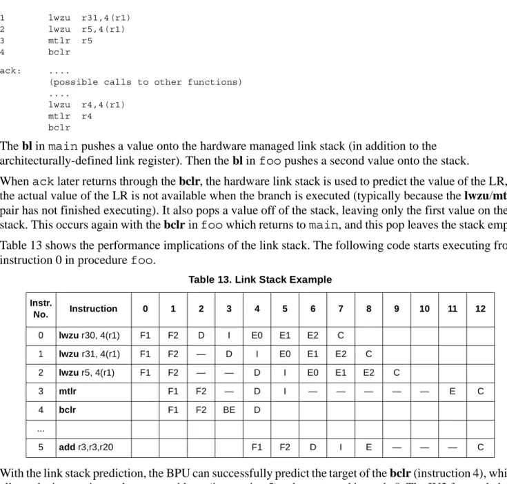
When ack later returns through the bclr, the hardware link stack is used to predict the value of the LR, if the actual value of the LR is not available when the branch is executed (typically because the lwzu/mtlr pair has not finished executing). It also pops a value off of the stack, leaving only the first value on the stack. This occurs again with the bclr in foo which returns to main, and this pop leaves the stack empty. Table 13 shows the performance implications of the link stack. The following code starts executing from instruction 0 in procedure foo.
With the link stack prediction, the BPU can successfully predict the target of the bclr (instruction 4), which allows the instruction at the return address (instruction 5) to be executed in cycle 8. The IU2 forwarded the LR value to the BPU in cycle 9 (which implies that the branch resolution occurs in cycle 10), even though it is not able to execute from an execution serialization viewpoint until cycle 11.
Without the link stack prediction, the branch would stall on the link register dependency and not execute until after the LR is forwarded (that is, branch execution would occur in cycle 10), which allows
instruction 5 not to execute until cycle 15 (seven cycles later than it executes with link stack prediction).
4.5.2
Position-Independent Code Example
Position-independent code is used when not all addresses are known at compile time or link time. Because performance is typically not good, position-independent code should be avoided when possible. The following example expands on the code sequence, which is described in Section 4.2.4.2, “Conditional
Table 13. Link Stack Example
Instr. No. Instruction 0 1 2 3 4 5 6 7 8 9 10 11 12 0 lwzu r30, 4(r1) F1 F2 D I E0 E1 E2 C 1 lwzu r31, 4(r1) F1 F2 — D I E0 E1 E2 C 2 lwzu r5, 4(r1) F1 F2 — — D I E0 E1 E2 C 3 mtlr F1 F2 — D I — — — — — E C 4 bclr F1 F2 BE D ... 5 add r3,r3,r20 F1 F2 D I E — — — C
Branch Control” in the Programming Environments for 32-Bit Implementations of the PowerPC Architecture.
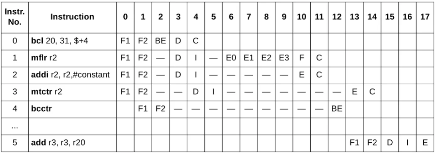
Because a return (bclr) is never paired with this bcl (instruction 0), the MPC7450 takes two special actions when it recognizes this special form (“bcl 20,31,$+4”):
• Although the bcl does update the link register as architecturally required, it does not push the value onto the link stack. Not pairing a return with this bcl prevents the link stack from being corrupted, which would likely require a later branch mispredict for some later bclr.
• Because the branch has the same next instruction address whether it is taken or fall-through, the branch is forced as a fall-through branch. This avoids a potential branch-taken bubble and saves a cycle.
The instruction address is available for executing a subsequent operation (instruction 2, addi) in cycle 10, primarily due to the long latency of the execution serialized mflr. However, the data has to be transferred back to the BPU through the CTR register, which prevents the bcctr from executing until cycle 12, so its target instruction (5) cannot start execution until cycle 17.
Note that it is important that instructions 3 and 4 be a mtctr/bcctr pair rather than a mtlr/bclr pair. A bclr would try to use the link stack to predict the target address, which would almost certainly be an address mispredict. This would be even more costly than the 7-cycle branch execution stall for instruction 4 shown in this example. In addition, an address mispredict would require that the link stack be flushed, which would mean that bclr instructions that occur later in the program would have to stall rather than use the link stack address prediction. This would further degrade performance.
4.5.3
Computed Branch and Function Pointer Examples
Computed branches are used in switch statements with enough different entries to warrant a table-lookup approach (instead of creating a series of if-else tests). The following example shows a typical
implementation of such a switch statement using the CTR register. Source code in C:
switch(x){
Table 14. Position-Independent Code Example
Instr. No. Instruction 0 1 2 3 4 5 6 7 8 9 10 11 12 13 14 15 16 17 0 bcl 20, 31, $+4 F1 F2 BE D C 1 mflr r2 F1 F2 — D I — E0 E1 E2 E3 F C 2 addi r2, r2,#constant F1 F2 — D I — — — — — E C 3 mtctr r2 F1 F2 — — D I — — — — — — — E C 4 bcctr F1 F2 — — — — — — — — — BE ... 5 add r3, r3, r20 F1 F2 D I E
case 0: /* code for case 0. */ break;
case 1: /* code for case 1. */ break;
case 2: /* code for case 2. */ break;
...
default: /* code for default case. */ break;
}
Assume r6 holds the address of SWITCH_TABLE for the following assembly code:
lwz r4,x
slwi r4, r4, 2 # Multiply by 4 to create word index.
lwzx r5, r4, r6 # r5 = SWITCH_TABLE[r4].
mtctr r5 # Move r5 to CTR.
bctr # Perform indirect branch.
Function pointers and virtual function calls should also use the CTR for their indirection, to avoid corrupting the hardware link stack. The following example shows a typical indirect function call. Note that the CTR is used to hold the target address, and the link form of the branch (bctrl) is used to save the return address.
Source code in C:
extern int (*funcptr)(); ...
a = funcptr();
Assume r9 holds the address of funcptr for the following assembly code:
lwz r0, 0(r9) # Load the value at funcptr.
mtctr r0 # Move it to the CTR.
bctrl # Perform indir. branch, save return address.
4.6
Branch Folding
Branches that do not set the LR or update the CTR are eligible for folding. In all three architectures, taken branches are folded immediately. For the MPC750 or the MPC7400, non-taken branches are folded at dispatch. In the MPC7450, not-taken branches cannot be fall-through folded if they are in IQ0–IQ2; however, branches are removed in the cycle after execution if they are in IQ3–IQ7.
5
Dispatch Considerations
The following is a list of resources required for MPC7450 to avoid stalls in the dispatch unit (IQ0–IQ2 are the three dispatch entries in the instruction queue):
• The appropriate issue queue is available. • The CQ is not full.
• Previous instructions in the IQ must dispatch. For example, IQ0 must dispatch for IQ1 to be able to dispatch.
The following sections describe how to optimize code for dispatch.
5.1
Dispatch Groupings
MPC7450 can dispatch a maximum throughput of three instructions per cycle. The dispatch process includes a CQ available check, an issue queue available check, a branch ready check, and a rename check. The dispatcher can send three instructions to the various issues queues, with a maximum of three to the GIQ, two to the VIQ, and one to the FIQ. Thus only two instructions can be dispatched per cycle to the AltiVec units (VIU1, VIU2, VPU, and VFPU). Only one FPU instruction can be dispatched per cycle, so three fadds take three cycles to dispatch.
The dispatcher also enforces a rule that only one load/store instruction can dispatch in any given cycle. The dispatcher can rename as many as four GPRs, three VRs, and two FPRs per cycle, so a
three-instruction dispatch window composed of vaddfp, vaddfp, and lvewx could be dispatched in one cycle.
Note that a load/store update form instruction (for example, lwzu), requires a GPR rename for the update. This means that an lwzu needs two GPR rename registers and an lfdu needs one FPU rename and one GPR rename. The possibility that one instruction may need two GPR rename registers means that even though the MPC7450 has a 16-entry CQ and 16 GPR rename registers, GPR rename registers could run out even though there is space in the CQ, as when eight lwzu instructions are in the CQ. Eight CQ entries are available, but because all 16 GPR rename registers are in use, no instruction needing a GPR target can be dispatched.The restriction of four GPR rename registers in a dispatch group means that the sequence lwzu,
add, add can be dispatched in one cycle. The instruction pair lwzu, lwzu also uses four GPR rename
registers and passes this rule but is disallowed by the rule that enforces a dispatch of only one load/store per cycle.
Table 15 contains a code example that shows a dispatch stall due to rename availability.
Table 15. Dispatch Stall Due to Rename Availability
Instr.
No. Instruction 0 1 2 3 4 5 6 7 8 9 ... 25 26 27 28 29 30
0 divw r4,r3,r2 F1 F2 D I E0 E1 E2 E3 E4 E5 ... E21 E22 C WB
1 lwzu r22,0x04(r1) F1 F2 D I E0 E1 E2 — — — ... — — C WB 2 lwzu r23,0x04(r1) F1 F2 — D I E0 E1 E2 — — ... — — — C WB 3 lwzu r24,0x04(r1) F1 F2 — — D I E0 E1 E2 — ... — — — — C WB 4 lwzu r25,0x04(r1) F1 F2 — — D I E0 E1 E2 ... — — — — — C 5 lwzu r26,0x04(r1) F1 F2 — — — D I E0 E1 ... — — — — — 6 lwzu r27,0x04(r1) F1 F2 — — — — D I E0 ... — — — — — 7 lwzu r28,0x04(r1) F1 F2 — — — — — D I ... — — — — — 8 lwzu r29,0x04(r1) F1 F2 — — — — — — ... — — — — D I
Instruction 8 stalls in cycle 9 because it needs 2 rename registers, and 15 rename registers are in use (1 for the divw, and 2 each for instructions 1 through 7). Since only 16 GPR rename registers are allowed, instruction 8 cannot be dispatched until at least one rename is released.
When the div later completes (cycle 27 in example above), rename registers are released during the write-back stage, and instruction 8 can thus dispatch in cycle 29.
Note that this code uses lwzu instructions, which require two rename registers, only to shorten the contrived code example. In general, sequences of lwzu instructions should be avoided for performance reasons, since they throttle dispatch to one lwzu instruction per cycle and completion to two lwzu instructions per cycle.
5.2
Dispatching Load/Store Strings and Multiples
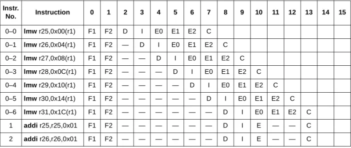
The MPC7450 splits load/store multiple instructions (lmw and stmw) and strings (lsw and stsw) into micro-operations at the dispatch point. The processor can dispatch only one micro-operation per cycle, which does not use the dispatcher to its full advantage. Using load/store multiple instructions is best restricted to cases where minimizing code size is critical or where there are no other available instructions to be scheduled, such that the under-utilization of the dispatcher is not a consideration.
Consider the following assembly instruction sequence:
0 lmw r25,0x00(r1) 1 addi r25,r25,0x01 2 addi r26,r26,0x01 3 addi r27,r27,0x01 4 addi r28,r28,0x01 5 addi r29,r29,0x01 6 addi r30,r30,0x01 7 addi r31,r31,0x01
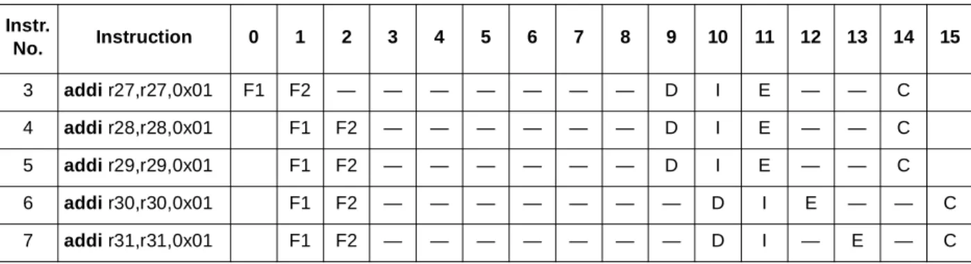
The load multiple instruction specified with register 25 loads registers 25–31. The MPC7450 splits this instruction into seven micro-operations at dispatch, after which the lmw executes as multiple operations, as Table 16 shows.
Table 16. Load/Store Multiple Micro-Operation Generation Example
Instr. No. Instruction 0 1 2 3 4 5 6 7 8 9 10 11 12 13 14 15 0–0 lmw r25,0x00(r1) F1 F2 D I E0 E1 E2 C 0–1 lmw r26,0x04(r1) F1 F2 — D I E0 E1 E2 C 0–2 lmw r27,0x08(r1) F1 F2 — — D I E0 E1 E2 C 0–3 lmw r28,0x0C(r1) F1 F2 — — — D I E0 E1 E2 C 0–4 lmw r29,0x10(r1) F1 F2 — — — — D I E0 E1 E2 C 0–5 lmw r30,0x14(r1) F1 F2 — — — — — D I E0 E1 E2 C 0–6 lmw r31,0x1C(r1) F1 F2 — — — — — — D I E0 E1 E2 C 1 addi r25,r25,0x01 F1 F2 — — — — — — D I E — — C 2 addi r26,r26,0x01 F1 F2 — — — — — — D I E — — C
Because the MPC7450 can dispatch only one LSU operation per cycle, the lmw is micro-oped at a rate of one per cycle and so in this example takes seven cycles to dispatch all the operations. However, when the last operation in the multiple is dispatched (cycle 8), instructions 1 and 2 can dispatch along with it. The use of load/store string instructions is strongly discouraged.
6
Issue Queue Considerations
Instructions cannot be issued unless the specified execution unit is available. The following sections describe how to optimize use of the three issue queues.
6.1
General-Purpose Issue Queue (GIQ)
As many as three instructions can be dispatched to the six-entry GPR issue queue (GIQ) per cycle. As many as three instructions can be issued in any order to the LSU, IU2, and IU1 reservation stations from the bottom three GIQ entries.
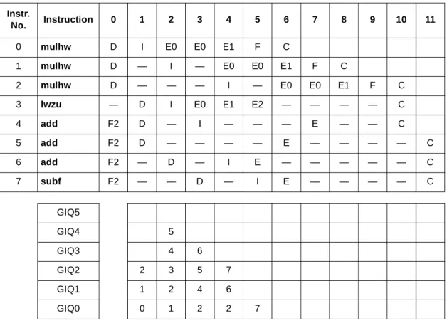
Issuing instructions out-of-order can help in a number of situations. For example, if the IU2 is busy and a multiply is stalled at the bottom GIQ entry (unable to issue because both IU2 reservation stations are being used), instructions in the next two GIQ entries can be issued to LSU or IU1s, bypassing that multiply. The following sequence is not well scheduled, but effectively, the MPC7450 micro-architecture dynamically reschedules around the potential multiply bottleneck.
0 xxxxxx00 mulhw r10,r20,r21 1 xxxxxx04 mulhw r11,r22,r23 2 xxxxxx08 mulhw r12,r24,r25 3 xxxxxx0C lwzu r13,0x4(r9) 4 xxxxxx10 add r10,r10,r11 5 xxxxxx14 add r13,r13,r25 6 xxxxxx18 add r14,r5,r4 7 xxxxxx20 subf r15,r6,r4
Table 17 shows the timing for the instruction in GIQ entries. Instruction 3 issues out-of-order in cycle 2; instructions 4 and 5 issue out-of-order in cycle 3.
Note that instruction 7 (subf) does not issue in cycle 4 because all three IU1 reservation stations have an instruction (4, 5, and 6). Instructions 4 and 5 are waiting in the reservation station for their source registers
3 addi r27,r27,0x01 F1 F2 — — — — — — — D I E — — C
4 addi r28,r28,0x01 F1 F2 — — — — — — D I E — — C
5 addi r29,r29,0x01 F1 F2 — — — — — — D I E — — C
6 addi r30,r30,0x01 F1 F2 — — — — — — — D I E — — C
7 addi r31,r31,0x01 F1 F2 — — — — — — — D I — E — C
Table 16. Load/Store Multiple Micro-Operation Generation Example (continued)
Instr.
to be forwarded from the IU2 and LSU, respectively. Because instruction 6 executes immediately after issue (in cycle 5), instruction 7 can issue in that cycle.
Similar examples could also be given for loads bypassing adds and multiplies bypassing loads. However, the ability to use out-of-order instructions is mostly across functional units and is extended somewhat for integer instructions beyond the functionality provided by MPC750 and MPC7400 processors.
6.2
Vector Issue Queue (VIQ)
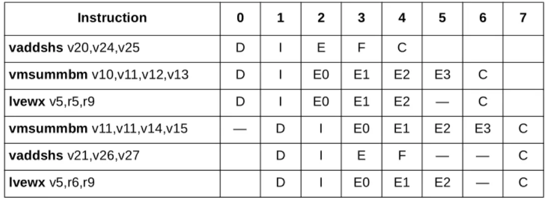
The four-entry vector issue queue (VIQ) handles all AltiVec computational instructions. Two instructions can dispatch to it per cycle, and it can issue two instructions in-order per cycle from its bottom two entries if reservation stations are available. The primary check is that a reservation station must be available.
NOTE
On the MPC7450, the VIQ can issue to any two vector units, as opposed to the MPC7400, which only allows pairing between VPU and one other unit.
Table 18 shows two cases where a vector add and a vector multiply-add (vmsummbm) start execution simultaneously (cycles 2 and 3). Note that the load-vector instructions go to the GIQ because its address source operands (rA and rB) are GPRs. This example also shows the MPC7450 ability to dispatch three instructions with vector targets in a cycle (cycles 0 and 1) as well as to retire three instructions with vector targets (cycle 7).
Table 17. GIQ Timing Example
Instr. No. Instruction 0 1 2 3 4 5 6 7 8 9 10 11 0 mulhw D I E0 E0 E1 F C 1 mulhw D — I — E0 E0 E1 F C 2 mulhw D — — — I — E0 E0 E1 F C 3 lwzu — D I E0 E1 E2 — — — — C 4 add F2 D — I — — — E — — C 5 add F2 D — — — — E — — — — C 6 add F2 — D — I E — — — — — C 7 subf F2 — — D — I E — — — — C GIQ5 GIQ4 5 GIQ3 4 6 GIQ2 2 3 5 7 GIQ1 1 2 4 6 GIQ0 0 1 2 2 7