Software Version 2.90
USER’S GUIDE TO:
PAGE
SECTION 1 - INTRODUCTION
10
TECHNICAL SUPPORT 11
SOFTWARE IMPROVEMENTS AND ADDITIONAL FEATURES 11
SECTION 2 - SOFTWARE INSTALLATIONS
22
PC requirements 22 SDK WINDOWS INSTALLATION 22 Windows Troubleshooting 24 SDK LINUX INSTALLATION 26 LABVIEW INSTALLATION 26 Linux Troubleshooting 27
SECTION 3 - READOUT MODES
28
INTRODUCTION 28
Full Vertical Binning 29
Single-Track 29
Multi-Track 30
Random-Track 31
Image 32
Cropped 33
SECTION 4 - ACQUISITION MODES
34
ACQUISITION MODE TYPES 34
Single Scan 35
Accumulate 36
Kinetic Series 37
Run Till Abort 39
Fast Kinetics 42
Frame Transfer 43
SDK
TABLE OF CONTENTS
Page 3
SECTION 7 - SHUTTER CONTROL
59
SHUTTER MODES 59
Fully Auto 59
Hold Open 59
Hold Closed 59
SHUTTER TYPE 60
SHUTTER TRANSFER TIME 61
SECTION 8 - TEMPERATURE CONTROL
63
SECTION 9 - SPECIAL GUIDES
64
CONTROLLING MULTIPLE CAMERAS 64
USING MULTIPLE CAMERA FUNCTIONS 65
DATA RETRIEVAL METHODS 67
How to determine when new data is available 67
Retrieving Image Data 69
DETERMINING CAMERA CAPABILITIES 70
Retrieving capabilities from the camera 70
Other Capabilities 74 Output Amplifiers 75 iCam 78 OptAcquire 80
SECTION 10 - EXAMPLES
84
INTRODUCTION 84RUNNING THE EXAMPLES 85
C 85
LabVIEW 85
Visual Basic 85
FLOW CHART OF THE FUNCTION CALLS NEEDED TO CONTROL ANDOR CAMERA 86
SECTION 11 - FUNCTIONS
91
AbortAcquisition 91 CancelWait 91 CoolerOFF 92 CoolerON 93 DemosaicImage 94 EnableKeepCleans 95 FreeInternalMemory 95 Filter_GetAveragingFactor 95 Filter_GetAveragingFrameCount 96 Filter_GetDataAveragingMode 96 Filter_GetMode 96Filter_GetThreshold 97 Filter_SetAveragingFactor 97 Filter_SetAveragingFrameCount 97 Filter_SetDataAveragingMode 98 Filter_SetMode 98 Filter_SetThreshold 98 GetAcquiredData 99 GetAcquiredData16 99 GetAcquiredFloatData 100 GetAcquisitionProgress 100 GetAcquisitionTimings 101 GetAdjustedRingExposureTimes 101 GetAIIDMAData 102 GetAmpDesc 102 GetAmpMaxSpeed 103 GetAvailableCameras 103 GetBackground 103 GetBaselineClamp 104 GetBitDepth 104 GetCameraEventStatus 105 GetCameraHandle 105 GetCameraInformation 106 GetCameraSerialNumber 106 GetCapabilities 107 GetControllerCardModel 123 GetCountConvertWavelengthRange 123 GetCurrentCamera 123 GetDDGPulse 124 GetDDGIOCFrequency 125 GetDDGIOCNumber 125 GetDDGIOCPulses 126 GetDetector 127 GetDICameraInfo 127 GetDualExposureTimes 127 GetEMCCDGain 128 GetEMGainRange 128 GetFastestRecommendedVSSpeed 129 GetFIFOUsage 129 GetFilterMode 129 GetFKExposureTime 130 GetFKVShiftSpeed 130 GetFKVShiftSpeedF 131 GetHardwareVersion 132 GetHeadModel 132 GetHorizontalSpeed 133
SDK
TABLE OF CONTENTS
Page 5
GetMCPGain 139 GetMCPGainRange 139 GetMCPVoltage 140 GetMetaDataInfo 140 GetMinimumImageLength 141 GetMostRecentColorImage16 142 GetMostRecentImage 143 GetMostRecentImage16 143 GetMSTimingsData 144 GetMSTimingsEnabled 144 GetNewData 144 GetNewData16 145 GetNewData8 145 GetNewFloatData 146 GetNumberADChannels 146 GetNumberAmp 146 GetNumberAvailableImages 146 GetNumberDevices 147 GetNumberFKVShiftSpeeds 147 GetNumberHorizontalSpeeds 147 GetNumberHSSpeeds 148 GetNumberNewImages 148 GetNumberPhotonCountingDivisions 149 GetNumberPreAmpGains 149 GetNumberRingExposureTimes 149 GetNumberIO 149 GetNumberVerticalSpeeds 151 GetNumberVSAmplitudes 151 GetNumberVSSpeeds 151 GetOldestImage 152 GetOldestImage16 152 GetPhysicalDMAAddress 153 GetPixelSize 153 GetPreAmpGain 153 GetPreAmpGainText 154 GetQE 154 GetReadOutTime 155 GetRegisterDump 155 GetRingExposureRange 155 GetSensitivity 156 GetSizeOfCircularBuffer 157 GetSlotBusDeviceFunction 157 GetSoftwareVersion 158 GetSpoolProgress 158 GetStatus 159 GetTemperature 160 GetTemperatureF 160 GetTemperatureRange 161 GetTemperatureStatus 161 GetTotalNumberImagesAcquired 161 GetIODirection 162 GetIOLevel 162 GetVersionInfo 163 GetVerticalSpeed 163 GetVirtualDMAAddress 164 GetVSSpeed 164 GPIBReceive 165GPIBSend 165 I2CBurstRead 166 I2CBurstWrite 166 I2CRead 167 I2CReset 167 I2CWrite 168 IdAndorDll 168 InAuxPort 168 Initialize 169 InitializeDevice 169 IsCoolerOn 170 IsCountConvertModeAvailable 170 IsInternalMechanicalShutter 170 IsAmplifierAvailable 171 IsPreAmpGainAvailable 171 IsTriggerModeAvailable 172 Merge 172 OA_AddMode 173 OA_DeleteMode 173 OA_EnableMode 174 OA_GetFloat 174 OA_GetInt 175 OA_GetModeAcqParams 175 OA_GetNumberOfAcqParams 176 OA_GetNumberOfPreSetModes 176 OA_GetNumberOfUserModes 176 OA_GetPreSetModeNames 177 OA_GetString 177 OA_GetUserModeNames 178 OA_SetFloat 179 OA_SetInt 179 OA_SetString 180 OA_WriteToFile 180 OutAuxPort 181 PrepareAcquisition 182 PostProcessCountConvert 183 PostProcessNoiseFilter 184 PostProcessPhotonCounting 185 SaveAsBmp 186 SaveAsCommentedSif 187 SaveAsEDF 187 SaveAsFITS 188 SaveAsRaw 188 SaveAsSif 189 SaveAsSPC 190
SDK
TABLE OF CONTENTS
Page 7
SetBackground 196 SetBaselineClamp 196 SetBaselineOffset 196 SetCameraStatusEnable 197 SetComplexImage 198 SetCoolerMode 199 SetCountConvertMode 200 SetCountConvertWavelength 200 SetCropMode 201 SetCurrentCamera 202 SetCustomTrackHBin 202 SetDACOutputScale 203 SetDACOutput 203 SetDataType 204 SetDDGAddress 204 SetDDGGain 204 SetDDGGateStep 204 SetDDGInsertionDelay 205 SetDDGIntelligate 205 SetDDGIOC 206 SetDDGIOCFrequency 207 SetDDGIOCNumber 208 SetDDGTimes 208 SetDDGTriggerMode 209 SetDDGVariableGateStep 209 SetDelayGenerator 210 SetDMAParameters 211 SetDriverEvent 212 SetDualExposureMode 213 SetDualExposureTimes 213 SetEMAdvanced 214 SetEMCCDGain 214 SetEMClockCompensation 215 SetEMGainMode 215 SetExposureTime 216 SetFanMode 216 SetFastKinetics 217 SetFastKineticsEx 218 SetFastExtTrigger 219 SetFilterMode 219 SetFilterParameters 219 SetFKVShiftSpeed 220 SetFPDP 220 SetFrameTransferMode 220 SetFullImage 221 SetFVBHBin 221 SetGain 222 SetGate 222 SetGateMode 223 SetHighCapacity 224 SetHorizontalSpeed 224 SetHSSpeed 225 SetImage 226 SetImageFlip 227 SetImageRotate 228 SetIsolatedCropMode 229 SetKineticCycleTime 230SetMCPGain 230 SetMCPGating 231 SetMessageWindow 231 SetMetaData 231 SetMultiTrack 232 SetMultiTrackHBin 233 SetMultiTrackHRange 233 SetNextAddress 234 SetNextAddress16 234 SetNumberAccumulations 234 SetNumberKinetics 234 SetNumberPrescans 235 SetOutputAmplifier 235 SetOverlapMode 236 SetPCIMode 237 SetPhotonCounting 238 SetPhotonCountingDivisions 238 SetPhotonCountingThreshold 238 SetPixelMode 239 SetPreAmpGain 240 SetRandomTracks 241 SetReadMode 242 SetRegisterDump 242 SetRingExposureTimes 243 SetSaturationEvent 244 SetShutter 245 SetShutterEx 246 SetShutters 247 SetSifComment 247 SetSingleTrack 247 SetSingleTrackHBin 248 SetSpool 249 SetSpoolThreadCount 250 SetStorageMode 250 SetTemperature 250 SetTriggerInvert 252 SetTriggerMode 252 SetIODirection 253 SetIOLevel 253 SetUserEvent 254 SetVerticalRowBuffer 254 SetVerticalSpeed 255 SetVirtualChip 255 SetVSAmplitude 256 SetVSSpeed 257
SDK
TABLE OF CONTENTS
Page 9
SECTION 13 - DETECTOR.INI
266
DETECTOR.INI EXPLAINED 266 [SYSTEM] 267 [COOLING] 268 [DETECTOR] 269 Format 269 DummyPixels 269 DataHShiftSpeed 269 DataVShiftSpeed 269 DummyHShiftSpeed 270 DummyVShiftSpeed 270 VerticalHorizontalTime 270 CodeFile 270 FlexFile 271 Cooling 271 Type 271 FKVerticalShiftSpeed 271 Gain 271 PhotonCountingCCD 271 EMCCDRegisterSize 272 iStar 272 SlowVerticalSpeedFactor 272 HELLFunction 272 HELLLoop1 272 ADChannels 272 AD2DataHSSpeed 272 AD2DumpHSSpeed 273 AD2BinHSSpeed 273 AD2Pipeline 273 iXon 273EXAMPLE DETECTOR.INI FILES 273
DH220 273 DV420 273 DV437 274 [CONTROLLER] 275 ReadOutSpeeds 275 PipeLine 275 Type 275
SECTION 1 - INTRODUCTION
The Andor Software Development Kit (SDK) gives the programmer access to the Andor range of CCD and Intensified CCD cameras. The key part of the SDK is the Dynamic Link Library (DLL) which can be used with a wide variety of programming environments, including, C, C++, C#, Visual Basic and LabVIEW. The library is compatible with Windows 2000, XP, Vista and Windows 7. A Linux version of the SDK is also available. Currently, Andor provides both 32-bit and 64-bit versions of the SDK, for Windows and Linux.
The SDK provides a suite of functions that allow you to configure the data acquisition process in a number of different ways. There are also functions to control the CCD temperature and shutter operations. The driver will automatically handle its own internal memory requirements.
To use the SDK effectively, the user must develop a software package to configure the acquisition, provide memory management, process the data captured, and create the user interface.
The manual is broken into several sections, and it is recommended that the user read Sections 1 - 10 before
starting to use the SDK. These sections describe the installation process, camera initialization/configuration and data capture.
Section 11 is a complete function reference detailing the function syntax, parameters passed and error codes
returned.
To further aid the user there is a comprehensive list of examples included with the SDK. The examples illustrate the use of C, Visual Basic and LabVIEW.
SDK
SECTION 1
Page 11
TECHNICAL SUPPORTContact details for your nearest representative can be found on our website.
SOFTWARE IMPROVEMENTS AND ADDITIONAL FEATURES
Version 2.90.30004.0
New features:
• USB iStar now supported
• Added function GetNumberPhotonCountingDivisions
• Added function GetPreAmpGainText
• Added 64-bit C# wrapper
• Added Shamrock C# wrapper
• Added 64-bit VB.NET header
• Added 64-bit LabVIEW support
•
Added support for 50kHz and 1MHz on iKonM-PV inspector systemBug fixes:
• GetKeepCleanTime not implemented for DV885
• The maximum binning should be limited by the size of the AD pipeline
• Recursive filter was not being reset between acquisitions.
• Frame Averaging filter was not working in frame transfer mode.
• Fixed crash on shudown with iKon-L
• Fixed crash if GetAcquisitionTimings is called for random tracks before tracks are set up.
• Removed some memory leaks
• Incorrect timings from GetAcquisitionTimings on Clara.
• Fixed saving random tracks to Fits.
• Luca S did not support temperature control.
• Minimum image length for a DU860 increased to 6 to avoid problems with isolated crop mode.
• Fixed SetPreAmpGain and IsPreAmpGainAvailable functions to check that the preamp gain index
parameter is within range.
•
Fixed data glitch on DV885 in frame transfer, external exposure mode (requires firmware upgrade)Version 2.88.30002.0
New features:
• Added SDK function IsCountConvertModeAvailable to limit acquisition settings available for count
convert.
• Added support for new iKon-L systems.
• Added support for new iKon-M systems.
• Added OptAcquire support for DV885 systems.
Bug fixes:
• Fixed race condition in WaitForAcquisitionTimeout.
• Image in crop mode on DU860 was shifting by 4 pixels for heights of less than 4.
• Fixed SR303 hardware issue where the step position of the wavelength drive will move when
powered on.
• SetPCIMode should return DRV_NOT_SUPPORTED when not using the CCI-23/CCI-24 card.
Version 2.88.30000.0
New features:
• Added OptAcquire feature to simplify configuration of iXon systems
• Added Count Convert feature to return data as photons or electrons
• Added Data Averaging feature for real time and post processing
• Added Spurious noise Filters for both real time and post processing
• Added Photon Counting post processing option
• Andor LabVIEW library updated to use version 8.0
• Added Dual Exposure Mode for iKon-L
• Updated SIFIO to enable the retrieval of calibration data
• Updated Shamrock SDK to include a calibration for Zolix spectrographs
• Added SDK function and capability for GetBaselineClamp
• Changed keep clean in FVB mode for iXon to prevent temperature drift
Bug fixes:
• Updated capability options for C#
• Updated Andor LabVIEW library
• Shutter open/close times fixed for Auto mode
• Fixed EM gain control when using multiple systems from the same executable
• Fixed isolated crop mode when data is being accumulated
• Fixed issues with control of multiple systems with multiple threads
• Fixed exposure time in software trigger mode when using large cycle time
• Fixed memory leak in GetAvailableCameras function
• Fixed random tracks stopping in video mode
Version 2.87.30000.0
New features:
• Clara E now supported
• Newton DU970/71P cameras now supported
• Cycle time reduced for imaging on Newton and iVac systems
• Number of accumulations can now be set in a kinetic series in overlap mode
• FVB cycle time reduced in crop mode provided only the height of the sensor has been cropped
Bug fixes:
• Clara near infra red mode not operating correctly when using FVB read mode
• Minimum exposure time increased to 1 millisecond for Clara near infra red mode
• Change to remove odd/even pixel noise after a number of accumulations in iDus
SDK
SECTION 1
Page 13
Version 2.86.30000.0
New features:
• Clara meta data now stored in sif file format
• Vertical and horizontal flip tags added to the FITS header
• Newton now supports multiple images per USB interrupt to reduce CPU load
• Support added for new revision of Newton DU920P
• Control of gate mode added to iStar floating toolbar
Bug fixes:
• Fixed bug where SetPhotonCountingThreshold was always returning DRV_NOT_SUPPORTED
• Fixed reported acquisition timings for external trigger non frame transfer mode
• Fixed the SDK flipper mirror issue (problem with the port numbers being used) and updated shipped
examples
• GetFIFOUsage is now thread safe
• USB driver for SR500 and SR750 updated to avoid conflicts with servo controllers
• Fixed External trigger, frame transfer, video mode operation
Version 2.85.30000.0
New features:
• Andor Clara image quality improved
• Option to run external exposure in a kinetic series for all cameras which support iCam
• Photon Counting check added to GetCapabilities
• Added kinetic cycle time tag to spooled tiff files
• PrepareAcquisition now returns an error if insufficient memory available
Bug fixes:
• SetSpool now returns DRV_NOT_AVAILABLE under Linux when trying to spool to FITS
• Fixed crash on initialize when no Andor cameras were connected
• Fixed problem with reinitializing Shamrock models SR500 and SR750
• Fixed problem where calling IsCoolerOn during an acquisition could stop the acquisition
• Fixed issue where events from a previous acquisition were not getting cleared
• Additional pixel shift removed from overlap mode on Clara
Version 2.84.30000.0
New features:
• Andor Clara now supported
SetDACOutput SetDACOutputScale GetNumberIO SetIODirection SetIOLevel GetIOLevel GetIODirection SetTriggerInvert IsAmplifierAvailable SetOverlapMode
SetMetaData GetMetaDataInfo Bug fixes:
• Spooled files beyond 4GB could not be opened
• Data was being lost when spooled files of small images went beyond 4GB
• Spooled FITS file had cycle time saved as 0
• IsPreAmpAvailable should use channel passed rather than current one
• Random tracks data corrupted for consecutive tracks for cameras other than iXon+
•
GetImages16 LabVIEW wrapper was calling wrong SDK functionVersion 2.83.30001.0
New features:
•
Added SetImageFlip and SetImageRotate functions to LabView wrapperBug fixes:
• Added ShamrockGetCalibration function to the Shamrock SDK help
Version 2.83.30000.0
New features:
• iVac systems now fully supported
• Shamrock spectrographs SR500 and SR750 now fully supported
• Fast kinetics now available for Luca-R
• Added High Capacity Mode support for DW936 cameras
Bug fixes:
• Fixes to Delphi header
• Fixed discrepancies between cycle times for multi-track and random track
• Fixed problem in fast kinetics when there was an odd number of super pixels
• Removed corrupted fire pulse in fast kinetics, external trigger
SDK
SECTION 1
Page 15
• Deprecated SetGain for SetMCPGain which is a more accurate naming convention
• Added Dud column support to SDK – allows SDK to be configured to interpolate bad columns
Bug fixes:
• Fixed minimum exposure for Luca-R
• Updated documentation – error code correction for get data functions.
• Fixed missing cases of GetTemperature in LabVIEW wrapper.
• Updated documentation – Corrected contact information.
• StartAcquisition now returns an error if horizontal binning does not divide evenly into range for
multi-tracks
• Fixed crash when StartAcquisition is called in random track mode before random tracks are setup
• Fixed default EM gain – Set to off when system initialized
• SetRandomTracks no longer returns an error if not in random track mode
• Image mode Linux example will now work with an InGaAs
• SetRandomTracks was not returning an error for certain incorrect track combinations
• Fixed SetBaselineClamp and SetBaselineOffset – The test for availability was not complete
• Fixed GetRingExposureRange - Now uses same limit as SetRingExposureTimes
• Fixed SetRandomTracks - Was failing for some valid tracks
• Fixed SetGain error code - Now returns DRV_NOT_SUPPORTED if not an ICCD
• Fixed bug in SetRandomTracks to prevent negative numbers for number of tracks with correct
return code
• GetAmpMaxSpeed now tests for NULL array parameter
• SetCustomTrackHBin returns DRV_NOT_SUPPORTED if not available for a system
• Fixed GetAmpDesc – Tests negative value for 3rd parameter – could cause crash
• Fixed GetAmpDesc – could return unterminated string
• Luca R cooler control was never supported but SDK returned DRV_SUCCESS - SDK functions
now return proper error codes
• Fixed bug in Initialisation/Shutdown cycling – could cause crash
• Extra fire pulse when using kinetic series external exposure on DU885
• Fixed incorrect data when using kinetic series external exposure on Luca-R
• Fixed external exposure trigger mode for Luca-S
Version 2.81.30004.0
New features:
• Improved noise performance on DZ936 cameras at 3 and 5MHz horizontal readout speeds
Bug fixes:
• None
Version 2.81.30003.1
New features:
Bug fixes:
• Fixed some documentation errors in LabVIEW context help
• Fixed Shamrock close and re-initialisation in C interface of Shamrock SDK
• Fixed Shamrock close operation in LabVIEW
Version 2.81.30002.0
New features:
• None
Bug fixes:
• Fixed cooling issue on Fibre Optic systems
• Fixed hot column issue on iXon DU888 cameras.
• Fixed crash in External Trigger on Newton
• Fixed DLL error on Windows Install program.
Version 2.81
New features:
• Improved shutdown in Linux during abnormal termination (Ctrl+C etc.) – signal handlers added
• CCI-24 support added to Linux SDK
Bug fixes:
• Removed Linux Device Driver compilation warnings for Kernel 2.6.23 and above.
• Crash could occur if GetAcquiredData was called before PrepareAcquisition or StartAcquisition.
• SetDriverEvent causes crash when called when system not initialized.
• GetImagesPerDMA did not return correct value unless PrepareAcquisition has been called.
• Timings incorrect for Frame Transfer in iCam mode.
• GetMostRecentImage[16] now returns correct data when used in Accumulate acquisition mode
• Fixed crash that would occur if GetNumberAvailableImages called before acquisition started
• Acquisitions now complete correctly if camera is reinitialised after being previously shutdown
SDK
SECTION 1
Page 17
• Added SetAccumulationCycleTime to LabVIEW library
• Random and multi tracks now available in frame transfer mode for iXon+
• SetNumberPrescans function added
• New timing functions added
GetKeepCleanTime
GetReadOutTime
Bug fixes:
• SetEMAdvanced was not working on Luca-R
• Random tracks external start was broken on a DU888
• InGaAs was not working in last release
• Multiple USB cameras could not be controlled
• Fast Kinetics external trigger was not working on early DV885 cameras
Version 2.79
New features:
• Memory allocation improved to allow larger kinetic series to be acquired without spooling
• Luca-R range supported
• iKon-L supported
• GetImageFlip and GetImageRotation added
• Multi tracks available in frame transfer mode for iXon+
• Random tracks available in frame transfer mode for iXon+
• Capability added to test for multi and random tracks in frame transfer
• SetMultiTrackHRange added
• Random tracks can now be configured with no gaps in between for iXon+
Bug fixes:
• Temperature drifting is now handled for all cameras
• GetTemperatureStatus did not return result for iXon
• Pixel values for last column on DU885 incorrect
• Fast kinetics, external trigger not operating correctly on a DU885
• Crash when initiailising multiple usb cameras
• Kinetic cycle time could not be set reliably
• Shutter timings not correct at 35MHz on a DU885
• SetShutter function not functioning correctly for iXon+
• Grams files created not compatible with certain software packages
• EM gain could not be turned off completely
• Glitches were found in fire pulse for FVB mode on iXon+
• Image flipping and rotation properties incorrect in sif file
• CCI-20 controller card not initialising (ERROR_ACK)
Version 2.78.5 New features:
• SetIsolatedCropMode added to LabVIEW library
• SaveAsTiffEx function added to provide choice of whether data is scaled Bug fixes:
SDK
SECTION 1
Page 19
Version 2.78
New features:
• Support for Luca 285 added.
• Data transfer from USB cameras improved.
• SetIsolatedCropMode function added to provide crop mode option (added for iXon+):
• Improved support for integrate on chip: Added
GetDDGIOCFrequency GetDDGIOCNumber SetDDGIOCNumber
• Option to export to raw data:
SaveAsRaw Bug fixes:
• SaveAsSif in SDK not storing readout speed correctly.
• Shutter now works correctly for Classic cameras when the software is run for the first time after rebooting PC.
• Data was wrapping at 65K if taking a kinetic series of accumulations.
Version 2.77
New features:
• Supports 32 and 64-bit Windows XP and Vista
• Moved to new USB device driver libUSB
• iCam: New Run Till Abort functionality for latest iXon (with CCI-23 controller card), and Luca
Cameras: SendSoftwareTrigger SetRingExposureTimes GetAdjustedRingExposureTimes GetNumberRingExposureTimes GetRingExposureRange IsTriggerModeAvailable
• New image manipulation functions:
SetImageFlip SetImageRotate
• Save as GRAMS SPC file format – SaveAsSPC
Version 2.76
New features:
• Additional capabilities added to GetCapabilities function
• GetAmpDesc function added
• Timeout added for WaitForAcquisition function
Bug fixes:
• Error returned if an invalid EM gain mode is selected
• Fixed issues with Fast Kinetics on an iXon
• Sometimes a camera was not ready to acquire when an acquisition event was sent
• Fixed initialization problem when a ‘.’ was in the path send to Initialize() function
Version 2.75
New features:
• Spooling to FITS, SIF and TIFF now available.
• SetBaselineOffset function added
• SetShutterEx added to control both an internal and external shutter through a DV8285
• SaveAsSif now handles spooled files Bug Fixes:
• GetNumberHSSpeeds now includes error checking for classics
• GetCapabilities returns correct bit depth for an iDus
• IsPreAmpGainAvailable now indicates yes for classic cameras as long as the gain index is zero and other parameters are valid
• EMGain Capability now returned correctly for iDus, Newton, USB iStar
• SaveAsBmp was not working in latest version
Version 2.74
SDK
SECTION 1
Page 21
Version 2.73
New features:
• Support for Newton and SurCam range of Cameras
Bug fixes:
• GetMostRecentImage does not now prevent access to images previous to the one obtained
SECTION 2 - SOFTWARE INSTALLATIONS
PC requirementsPlease consult the Specification Sheet for your camera for the minimum and the recommended PC requirements.
SDK WINDOWS INSTALLATION
The installation of the Andor SDK software is a straightforward process, the steps for which are outlined below. Before proceeding with the installation, it is recommended that you read the remainder of this section first.
1. Insert the CD supplied with the SDK, and execute the "SETUP.EXE" program. This will take you through the complete installation process. You will be prompted to select the type of camera you have purchased as the installation needs to configure, were required, the "Detector.ini" file appropriately. You will also be requested to select a destination directory; this should be a directory that all users planning to use the SDK have full read/write privileges to. The directory will be created if it does not already exist. It is recommended that if you are performing an upgrade or reinstall that you do it to a clean directory.
Example programs will be copied into sub-directories of the installation directory specified above.
2. If not already installed, proceed with installing camera hardware. Consult your User guide for details. You may have to restart the PC to complete the installation
3. Navigate to the directory ‘<destination directory>\Examples\C’ directory. Go into any
sub directory and run the ‘.exe’ file that you see there. If this runs successfully then your installation has completed. If it does not run with a successful message please consult the troubleshooting guide later in this section.
The installation process will copy the following files into the specified base directory:
ATMCD32D.DLL (32-bit Dynamic Link Library) ATMCD64D.DLL (64-bit Dynamic Link Library)
DETECTOR.INI (Classic CCD, ICCD and iStar cameras only) ATMCD32D.H ( C, C++ only)
SDK
SECTION 2
Page 23
run as a stand-alone program.
A device driver required to support the camera will also be installed. The actual driver installed will depend on the camera type and operating system version, i.e.:
• For PCI systems the driver file is atmcdwdm.sys for 32-bit operating systems, or
atmcdwdm64.sys for 64-bit operating systems.
• For USB cameras the driver file is libusb0.sys for 32-bit operating systems, or libusb0_x64.sys for 64-bit operating systems.
NOTE: Do not have more than one example or other SDK software (e.g. Andor Solis™, iQ™) running at the same time.
Windows Troubleshooting
Installing on Windows 7
• Some users have experienced difficulty installing the SDK on Windows 7, if so please see the Window 7 Driver Installation Guide.
If you are running a PCI camera
• Check that the Andor Technology PCI driver appears in the Ensure that an Andor section in exists
in the Device Manager and that an Andor Technology PCI driver appears in it. To access the Device Manager, go to the Control Panel and click on the “System” control. From here, select the Hardware tab and then click on the Device Manager button.
• Shut down the PC and ensure that the PCI card is seated correctly
• For 32-bit OS, ensure that the file atmcdwdm.sys file appears in the
C:\WINDOWS\system32\drivers directory. The latest version is 4.29.0.0
• For 64-bit OS, ensure that the file atmcdwdm64.sys file appears in the
C:\WINDOWS\system32\drivers directory. The latest version is 4.29.0.0
• If the Windows NT driver atmcd.sys is in the “Drivers” directory delete it and restart the PC.
If you are experiencing communication problems with the Andor USB cameras carry out the following
actions:
• Confirm that the PC being used is USB 2.0 compatible and that a USB 2.0 port is being used for the
camera
• Check the power to the iDus camera.
• Check the USB cable from the PC to the iDus camera.
• Ensure that a LibUSB-Win32 Devices section exists in the Device Manager and tab and that your
camera is listed. To access the Device Manager, go to the Control Panel and click on the “System” control. From here, select the Hardware tab and then click on the Device Manager button. If the entry does not exist or there is an exclamation mark beside it carry out the following actions
1. Power the camera off and on and after the new hardware is detected, follow the instructions to install a driver for the new device. When asked for a location, point to the directory where the
software was installed.
2. If there is a USB device with an exclamation mark beside it and you cannot account for this device then it is probably the Andor camera and the driver is not installed. Install the driver as
SDK
SECTION 2
Page 25
SDK LINUX INSTALLATION
The first step is to unpack the archive that you have received. With the following steps replace <version> with the version number of the archive you have. E.g. 2.15
1. Open a terminal
2. Change the directory to where the andor-<version>.tar.gz file is located
3. Type 'tar -zxvf andor-<version>.tar.gz'
A new directory named 'andor' is created.
To install the SDK run the script ‘install_andor’ from the ‘andor’ directory. See the ‘INSTALL’ file located in the same directory, for further information.
LABVIEW INSTALLATION
When you install the SDK onto a machine with LabVIEW installed, the SDK DLL and LabVIEW files are automatically copied into the LabVIEW install directory.
All Andor SDK function wrappers are present in a LabVIEW library file, "atmcd32d.llb", installed in your “user.lib” directory in you LabVIEW install folder.
The library can be added to any of your palette views. Instructions for adding the SDK to your palette view are described below.
Note: Depending on the version of LabVIEW you are using, the menu structure may be different. Please
consult your LabVIEW manual for general help on adding LLBs if you have any issues.
1) Select the menu item "Tools -> Advanced -> Edit Palette Views..." 2) Right Click on the Functions tool bar & select "Insert -> Submenu..." 3) In the dialog select "Link to LLB library..."
4) Navigate to the user.lib directory and select "atmcd32d.llb" - The submenu with all SDK functions has been added
5) Right click on the new palette view and select "Rename Submenu..." 6) Change the name to "Andor SDK"
SDK
SECTION 2
Page 27
Linux Troubleshooting If you are having trouble running your camera under the Linux operating system please check the following
before contacting Technical Support
For PCI,
• Check that the device driver is loaded. Type ‘/sbin/lsmod’ – andordrvlx should be listed.
For USB,
• Check that libUSB is available, ‘whereis libusb’
• Check that the Andor device is listed in the /proc/bus/usb/devices file.
SECTION 3 - READOUT MODES
INTRODUCTIONAndor systems are based on a detector known as a Charged Coupled Device (CCD). The detector is divided
up as a 2-dimensional array of pixels, each capable of detecting light. For example, systems based on an
EEV 30-11 CCD chip have 1024 X 256 pixels, where each pixel is 26µm2 (all examples given in this manual
assume an EEV 30-11 based system). This 2-dimensional nature allows the device to be operated using a
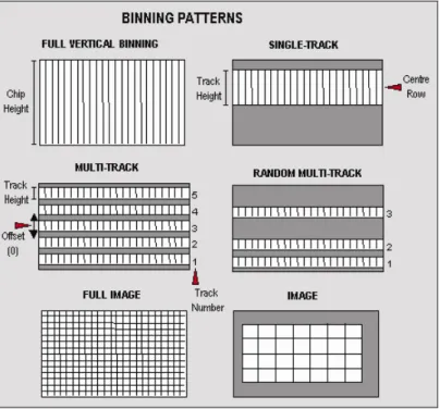
number of different binning patterns. We refer to these binning patterns as Readout Modes.
Andor has several different readout modes as follows:
• Full Vertical Binning (FVB)
• Single-Track
• Multi-Track
• Random-Track
• Image
• Cropped
Figure 1 shows the binning patterns :
SDK
SECTION 3
Page 29
Full Vertical Binning Full Vertical Binning (FVB) is the simplest mode of operation. It allows you to use the CCD chip as a Linear Image Sensor (similar to a photo diode array). The charge from each column of pixels is vertically binned into the shift register. This results in a net single charge per column. Therefore, for a 30-11 CCD an acquisition using FVBwill result in 1024 data points.
To set-up a Full Vertical Binning acquisition call: SetReadMode(0)
Figure 2: Full Vertical Binning
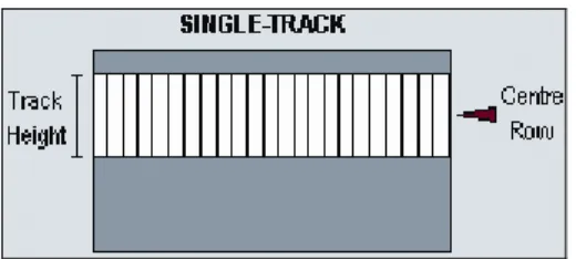
Single-Track
Single-Track mode is similar to the Full Vertical Binning mode discussed previously in that upon completion
of an acquisition you will have a single spectrum. However, that is where the similarities end.
With Single-Track you can specify not only the height (in pixels) of the area to be acquired but also its vertical position on the CCD. To ensure the best possible Signal to Noise ratio all the rows within the specified area are binned together into the shift register of the CCD and then digitized.
Figure 3: Single-track
Single-Track mode is useful because you are able to precisely define only the area of the CCD sensor that is illuminated by light. This is particularly important in low light level applications as it allows you to minimize the contribution of dark current in the measured signal. Also, if you are using an imaging spectrograph, such as the Shamrock, with a multiple core fiber, this mode allows you to select a single fiber for examination.
To set-up a Single-Track acquisition you need to call the following functions:
SetReadMode(3);
SetSingleTrack(128,20);
NOTE: If a non frame-transfer camera is used, a shutter may be required to prevent light (which would otherwise fall on the CCD-chip outside the specified track) from corrupting the data during binning.
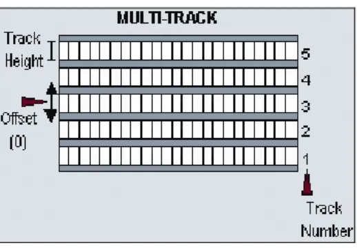
Multi-Track Multi-Track mode allows you to create one or more tracks (each of which behaves like the Single-Track above). With Multi-Track you specify the number of tracks and the track height. The driver internally sets the actual position of each track so that the tracks are evenly spaced across the CCD. The tracks can be vertically shifted, en masse, by specifying a positive or negative offset about a central position. For greater
control over the positioning of the tracks use Random-Track mode.
Figure 4: Multi-Track
Multi-Tracks will allow you to simultaneously acquire a number of spectra, delivered typically via a fiber bundle. If you are using a non-frame transfer camera and a continuous source, you will need to use a shutter
to avoid streaking the spectra during the binning process. Please refer to SECTION 8 - SHUTTER
CONTROL for further information.
To set-up a Multi-Track acquisition you need to call the following functions:
SetReadMode(1);
SetMultiTrack(5,20,0,bottom, gap);
The SetMultiTrack function also returns the position of the first pixel row of the first track “bottom”, together
with the gap between tracks, “gap”. This allows the user to calculate the actual position of each track.
NOTE:
1. Before using Multi-Track mode with fiber bundles it is often useful to acquire a full resolution image of the output. Having observed the vertical position and spacing of the individual spectra, you can vary track height and offset accordingly.
2. Imaging spectrographs vertically invert input light (i.e. light from the top fiber will fall on the
SDK
SECTION 3
Page 31
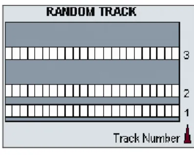
Random-Track In Random-Track mode the position and height of each track is specified by the user, unlike Multi-Track mode were the driver sets the position of each track automatically.
Figure 5: Random-Track
Random-Track will allow you to simultaneously acquire a number of spectra, delivered typically via a fiber bundle. Unless you are acquiring data from a pulsed source you will need to use a shutter to avoid streaking the spectra during the binning process. To set-up a Random-Track acquisition you need to call the following functions:
SetReadMode(2); int position[6]; position[0] = 20;
position[1] = 30; //end of track 1, 11 rows height position[2] = 40; //start of track 2
position[3] = 40; //end of track 2, 1 row height position[4] = 100; //start of track 3
position[5] = 150; //end of track 3, 51 rows height
SetRandomTracks(3,position);
The SetRandomTracks function validates all the entries and then makes a local copy of the tracks positions. For the array of tracks to be valid the track positions MUST be in ascending order.
NOTES:
1. A track of 1 row in height will have the same start and end positions.
2. Before using Random-Track mode with fiber bundles it is often useful to acquire a Full Resolution Image of the output.
3. Having observed the vertical positions of the individual spectra set the Random-Track mode accordingly.
4. Imaging spectrographs vertically invert input light (i.e. light from the top fiber will fall on the bottom track on the CCD-chip.)
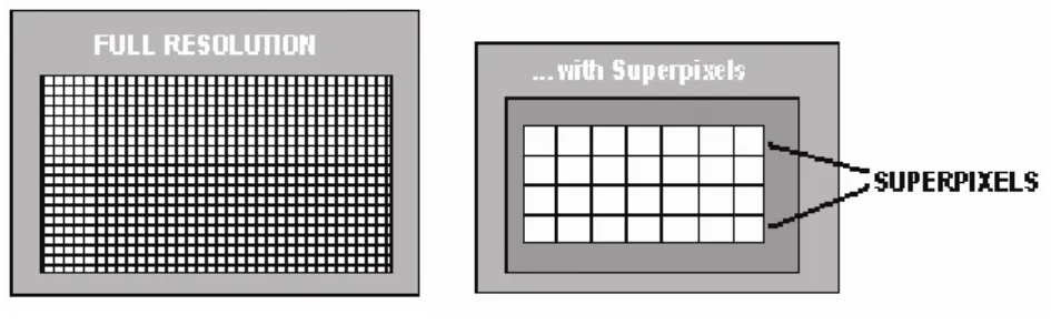
Image In Image mode the CCD is operated much like a camera. In this mode you get a measured value for each pixel on the CCD, in effect allowing you to ‘take a picture’ of the light pattern falling on the pixel matrix of the CCD. To prevent smearing the image, light must be prevented from falling onto the CCD during the readout
process. Please refer to SECTION 8 - SHUTTER CONTROL for further information.
Figure 6: Image mode
To reduce the file size and increase the speed of readout it is possible to specify a sub-area of the CCD to be read out. It is also possible to bin pixels together horizontally and vertically to create super pixels.
To set up a “Full Resolution Image” acquisition you need to call the following functions:
SetReadMode(4);
SetImage(1,1,1,1024,1,256);
To acquire a sub-area with lower left co-ordinates of (19, 10), with binning of 4 in both the horizontal and vertical directions, and 100x16 pixels in the acquired image you would call the SetImage function with the following parameters:
SetImage(4,4,19,118,10,25);
By a process of binning charge vertically into the shift register from several rows at a time (e.g. 4) and then binning charge horizontally from several columns of the shift register at a time (e.g. 4) the ANDOR SDK system is effectively reading out charge from a matrix of super pixels which each measure 4 x 4 real pixels. The result is a more coarsely defined image, but faster processing speed, lower storage requirements, and a better signal to noise ratio (since for each element or super pixel in the resultant image, the combined charge from several pixels is being binned and read out, rather than the possibly weak charge from an individual pixel).
SDK
SECTION 3
Page 33
Cropped In Cropped mode, we can "fool" the sensor into thinking it is smaller than it actually is, and readout continuously at a much faster frame rate. The spectral time resolution is dictated by the time taken to readout the smaller defined section of the sensor.
If your experiment dictates that you need fast time resolution but cannot be constrained by the storage size of the sensor, then it is possible to readout the EMCCD in a "cropped sensor" mode, as illustrated below.
Figure 7: Cropped mode
To set up the CCD with a cropped image, as in figure 7, see SetIsolatedCropMode.
NOTE: It is important to ensure that no light falls on the excluded region otherwise the
acquired data will be corrupted.
SECTION 4 - ACQUISITION MODES
ACQUISITION MODE TYPESIn the previous section the different ReadOut Modes (binning patterns) supported by the Andor SDK were discussed. In addition the Andor SDK allows you to control the number and the timing details of acquisitions made using the various binning patterns. To simplify the process of controlling these acquisitions the Andor SDK has
divided the acquisition process into several different Acquisition Modes:
• Single Scan
• Accumulate
• Kinetic Series
• Run Till Abort
• Fast Kinetics
Single Scan is the simplest form of acquisition where a single scan is captured. Accumulate mode takes a sequence of single scans and adds them together.
Kinetic Series mode captures a sequence of single scans, or possibly, depending on the camera, a sequence of accumulated scans.
Run Till Abort continually performs scans of the CCD until aborted.
If your system is a Frame Transfer CCD, the acquisition modes can be enhanced by setting the chip operational
mode to Frame Transfer.
In the remainder of this section we will discuss in detail what each of these modes actually are and what needs to be specified to fully define an acquisition.
The table below summarizes the information that is needed for each acquisition mode:
MODE EXPOSURE TIME ACCUMULATE CYCLE TIME NO. OF ACCUMULATIONS KINETIC CYCLE TIME NO. IN KINETIC SERIES SINGLE SCAN X ACCUMULATE X X X
SDK
SECTION 4
Page 35
Single Scan Single Scan is the simplest acquisition mode available with the Andor system. In this mode Andor SDK performs one scan (or readout) of the CCD and stores the acquired data in the memory of the PC.
To set the acquisition mode to Single Scan call:
SetAcquisitionMode(1)
SetExposureTime(0.3)
Here the exposure time is the time during which the CCD sensor is sensitive to light. The exposure time is set
via the SetExposureTime function.
NOTE: Due to the time needed to shift charge into the shift register, digitize it and operate shutters, where necessary, the exposure time cannot be set to just any value. For example, the minimum exposure time depends on many factors including the readout mode, trigger mode and the digitizing rate. To help the user determine what the actual exposure time will be the driver automatically calculates the nearest allowed value, not less than the user’s choice. The actual calculated exposure time used by Andor SDK may be obtained via the GetAcquisitionTimings function (this function should be called after the acquisition details have been fully defined i.e. readout mode, trigger mode etc. have been set).
Accumulate Accumulate mode adds together (in computer memory) the data from a number of scans to form a single ‘accumulated scan’. This mode is equivalent to taking a series of Single Scans and “manually” adding them together. However, by using the built-in Accumulate mode you gain the ability to specify the time delay (or period) between two consecutive scans and also the total number of scans to be added.
To set the acquisition mode to Accumulate call: SetAcquisitionMode (2)
To fully define an Accumulate acquisition you will need to supply the follow information:
Exposure Time. This is the time in seconds during which the CCD sensor collects light prior to readout. Set
via the SetExposureTime function.
Number of Accumulations. This is the number of scans to be acquired and accumulated in the memory of
the PC. Set via the SetNumberAccumulations function.
Accumulate Cycle Time. This is the period in seconds between the start of each scan.
Set via the SetAccumulationCycleTime function. (This parameter is only applicable if you have selected
Internal trigger – Please refer to SECTION 6 – TRIGGERING for further information.
NOTES:
1. If the exposure time or the cycle time are set too low or are not permissible values, the driver will automatically calculate the nearest appropriate value.
2. The actual values used can be obtained via the GetAcquisitionTimings function (this
function should be called after the acquisition has been fully defined (i.e. readout mode, trigger mode etc. have been set).
SDK
SECTION 4
Page 37
Kinetic Series
Kinetic Series mode captures a sequence of single scans, or a sequence of accumulated scans, into
memory. This mode is equivalent to manually taking a series of single scans (or accumulated scans). However, by using the built-in Kinetic Series mode you gain the ability to specify the time delay (or period) between two consecutive scans and also the total number of scans to be acquired.
NOTE: In External Trigger mode the delay between each scan making up the acquisition is not under
To set the acquisition mode to Kinetic Series call:
SetAcquisitionMode(3)
To fully define a Kinetic Series acquisition you will need to supply the following information:
Exposure Time. This is the time in seconds during which the CCD collects light prior to readout.
Set via the SetExposureTime function.
Number of Accumulations. This is the number of scans you want to add together to create each member of
your kinetic series. The default value of 1 means that each member of the kinetic series will consist of a single scan.
Set via the SetNumberAccumulations function.
Accumulate Cycle Time. This is the period in seconds between the start of individual scans (see Number of
Accumulations above) that are accumulated in computer memory to create each member of your kinetic
series - each member of the series is an ‘accumulated scan’.
Set via the SetAccumulationCycleTime function.
(This parameter is only applicable if you have selected the Internal trigger and the Number of Accumulations
is greater than 1- Please refer to SECTION 6 – TRIGGERING for further information.)
Number in Kinetic Series. This is the number of scans (or ‘accumulated scans’) you specify to be in your series.
Set via the SetNumberKinetics function.
Kinetic Cycle Time. This is the period in seconds between the start of each scan (or set of accumulated
scans, if you have set the Number of Accumulations to more than 1) in the series.
SDK
SECTION 4
Page 39
Run Till Abort
Run Till Abort mode continually performs scans of the CCD at the rate set by the user, until the acquisition is
stopped by calling the AbortAcquisition function. The minimum possible delay between each scan will be the
minimum Kinetic Cycle Time.
To set the acquisition mode to Run Till Abortcall:
SetAcquistionMode(5) SetExposureTime(0.3) SetKineticCycleTime(0)
Here the exposure time is the time during which the CCD sensor is sensitive to light. NOTES:
1. The total number of images acquired during the acquisition can be obtained at any time by
calling the GetTotalNumberImagesAcquired function. The data acquired during the
acquisition will be stored in the circular buffer until it is overwritten by new scans. The
capacity of the circular buffer can be obtained by calling the GetSizeOfCircularBuffer
function. To retrieve all valid data from the circular buffer before it is overwritten by new data the GetNumberNewImages and GetImages functions should be used. Alternatively, to retrieve
only the most recent image the GetMostRecentImage function can be used. Finally, to retrieve
the oldest image the GetOldestImage function can be used.
2. Due to the time needed to shift charge into the shift register, digitize it and operate shutters, where necessary, the exposure time cannot be set to just any value. For example, the minimum exposure time depends on many factors including the readout mode, trigger mode and the digitizing rate. To help the user determine what the actual exposure time will be, the driver automatically calculates the nearest allowed value that is not less than the user’s choice. Thus, the actual calculated exposure time used by Andor SDK may be obtained via
GetAcquisitionTimings (this function should be called after the acquisition details have been fully defined i.e. readout mode, trigger mode etc. have been set).
iCam Run Till Abort When in this mode of operation (Run Till Abort) some systems have an enhanced trigger mode and enhanced exposure time capability. To check if these enhanced features are available with your system,
use the function GetCapabilities and check the ulTriggerModes variable for bit 3
(AC_TRIGGERMODE_CONTINUOUS) being set.
The enhanced features include:·
1. Ring of exposures
2. Software Trigger or External trigger
3. Ability to change exposure times during acquisition without aborting the run.
4. External Level Exposure (Bulb) Trigger
These enhanced features are particular useful in situations where you need to acquire data at a fast rate but not at some predefined rate or when you need to change the exposure time between successive scans. A good example would be calcium imaging where you need to take 2 images at different wavelengths with possibly different light levels. With this new mode of operation you would set the experiment up as follows:
1. Configure the camera to acquire an image SetReadMode, SetImage, SetFrameTransferMode
2. Select Run-till-abort mode SetAcquisitionMode
3. Select Software trigger SetTriggerMode(10)
Confirm with IsTriggerModeAvailable(10)
4. Set exposure time. SetExposureTime or SetRingExposureTimes
5. Move filter to first position
6. Start acquisition. StartAcquisition
7. Send software Trigger. SendSoftwareTrigger
8. Wait for an acquisition event. See SetDriverEvent
9. Move Filter to next position.
10. Change exposure time. See SetExposureTime
SDK
SECTION 4
Page 41
acquisition while the readout of the first scan is still in progress. See SetAcqStatusEvent.
NOTE: This will also work in External trigger mode SetTriggerMode, with an external trigger source
determining the start of an exposure instead of the SendSoftwareTrigger command. In external
trigger care must be taken to ensure that the external trigger occurs when the camera is ready for it i.e. the frequency of the external trigger source has to be within the capabilities of the camera with the current settings.
With External Exposure trigger mode the width of the trigger pulse source will determine the exposure time and the Ring of Exposures will not be applicable.
See also Acquisition Modes. GetAdjustedRingExposureTimesGetNumberRingExposureTimes
GetRingExposureRangeIsTriggerModeAvailableSendSoftwareTriggerSetRingExposureTimes SetTriggerMode
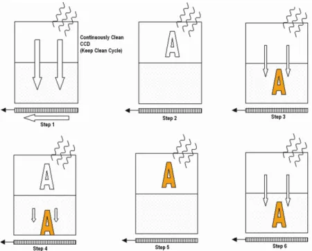
Fast Kinetics
Fast Kinetics is a special readout mode that uses the actual sensor as a temporary storage medium and
allows an extremely fast sequence of images to be captured. The capture sequence is described with the following steps:
Step 1: both the Image and Storage areas of the sensor are fully cleaned out (the Keep Clean Cycle)
Step 2: the Keep Clean Cycle stops and the acquisition begins. The image builds up on the illuminated section
of the sensor which is typically a small number of rows at the top of the sensor
Step 3: the sensor remains in this state until the exposure time has elapsed, at which point the complete
sensor is clocked vertically by the number of rows specified by the user.
Steps 4 & 5: the process is continued until the number of images stored equals the series length set by the
user.
Step 6: at this point the sequence moves into the readout phase by first vertically shifting the first image to the bottom row of the sensor. The sensor is then read out in the standard method.
Points to consider for Fast Kinetics Mode:
• Light MUST only be allowed to fall on the specified sub-area. Light falling anywhere else will contaminate the data.
• The maximum number of images in the sequence is set by the position of the area, the height of the sub-area and the number of rows in the CCD (Image and Storage sub-area)
• There are no Keep Clean cycles during the acquisition sequence.
• The industry fastest vertical shift speeds of the iXonEM+ enables fastest time resolution with minimal vertical smearing.
SDK
SECTION 4
Page 43
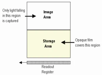
Frame Transfer Frame transfer is a mode of operation of the chip that is only available if your system contains a Frame
Transfer CCD (FT CCD).It can be switched on for any acquisition mode.
A FT CCD differs from a standard CCD in 2 ways:
• Firstly, a FT CCD contains 2 areas, of approximately equal size (see figure 7 below).
1. The first area is the Image area, this area is at the top and farthest from the readout register. It is in this area that the CCD is sensitive to light.
2. The second area is the Storage area and sits between the Image area and the readout register. This area is covered by an opaque mask, usually a metal film, and hence is not sensitive to light.
• The second way in which a FT CCD differs from a standard CCD is that the Image and the Storage
areas can be shifted independently of each other.
These differences allow a FT CCD to be operated in a unique mode where one image can be read out while the next image is being acquired. It also allows a FT CCD to be used in imaging mode without a shutter.
Figure 8 takes you through the capture sequence for an FT CCD:
Figure 8: Capture sequence for a Frame Transfer CCD
Step 1: Both Image and Storage areas of the CCD are fully cleaned out. This is known as a Keep Clean
Cycle. Keep Clean Cycles occur continuously to ensure that the camera is always ready to start an
acquisition when required.
Step 2: On receipt of a start acquisition command the CCD stops the Keep Clean Cycle. This allows the image, photoelectric charge, to build up in the Image area of the CCD. The CCD remains in this state until the exposure time has elapsed, at which point the readout process starts.
Step 3: In this step the charge, built up in the Image area, is quickly shifted into the Storagearea. The time
required to move the charge into the storage area is calculated as follows:
No. of Rows in the ImageArea x Vertical Shift Rate.
Once the Image area has been shifted into the storage area the Image area stops vertically shifting and begins to accumulate charge again, i.e. the next exposure starts.
Step 4: While the Imagearea is accumulating charge the Storage area is being read out. This readout phase
SDK
SECTION 4
Page 45
• The Accumulation Cycle Time and the Kinetic Cycle Time are fully dependent on the
exposure time and hence cannot be set via the software.
• For our Classic CCD range of cameras with frame transfer type sensors the camera can be
operated in External Trigger mode. In this mode there are no keep cleans and the external trigger starts the "Readout" phase. The exposure time is the time between external triggers and hence the user cannot set the exposure or cycle times.
• For our iXon range of cameras the external trigger mode is more flexible. With these
cameras the user can define the amount of time between the external trigger event occurring and the readout starting. This can be useful in those situations where the TTL trigger occurs before the light event you are trying to capture. As in the Classic Camera case, no keep cleans are running and the true exposure time is the time between triggers. However, the exposure window has moved in time by the exposure time.
• There is no need for a mechanical shutter. As the exposure time is long compared to the
time required to shift the image into the storage area and therefore, image streaking will be
It is also possible to operate a FT CCD in a non-frame transfer mode. In this standard mode of operation, an FT CCD acts much like a standard CCD. The capture sequence for this standard mode is illustrated here:
• Step 1: Both Image and Storageareas of the CCD are fully cleared out (the Keep Clean Cycle).
• Step 2: When an acquisition begins, the CCD stops the Keep Clean Cycle. The image builds up in
the Image area of the CCD. The CCD remains in this state until the exposure time has elapsed, at which point the readout process starts.
• Step 3: The charge built up in the Image area is quickly shifted, into the Storage area. The time required to move the charge into the Storage area is the same as in the Frame Transfer mode.
• Step 4: With the image now in the Storage area the captured image is read out. The time taken to
read out the image is again the same as in the Frame Transfer mode.
• Step 5: On completion of the readout, the CCD is again completely cleared, ready to acquire the next
image. The CCD remains in the Keep Clean Cycle until the end of the accumulation or kinetic cycle time, depending on the acquisition mode, i.e. back to Step 1. As at least one Keep Clean Cycle is performed between each exposure, the minimum exposure time is no longer set by the time to read out the image.
SDK
SECTION 4
Page 47
NOTES:
• When using an FT CCD as a standard CCD, the Exposure Time, Accumulation Cycle Time
and Kinetic Cycle Time can be set independently.
• The minimum exposure time is not related to the time taken to read out the image.
• External trigger operates as if the CCD was a Non-FT CCD.
• As the captured image is quickly shifted into the storage area, even in non-frame transfer
mode, the system may still be used without a mechanical shutter.
• For short exposure times the image may appear streaked as the time taken to shift the
image area into the storage area may be of similar magnitude.
• Light falling on the Image area while the Storage area is being read out may contaminate
the image in the Storage area due to charge spilling vertically along a column from the Image area. The slower the readout rate or the shorter the exposure time the greater the possibility of corruption. To see why this is the case, consider the following situation:
“During a 100us exposure enough light has fallen on a pixel to register 10000 counts, or 100,000 electrons assuming 10e/count. The image is then shifted into the Storage area. To read out the image, assuming 1000x1000 pixels, it would take approximately 100ms at 10MHx readout rate. This means that during the reading out of the image 10 million counts (10000 * 1000) will have been acquired into the pixel described above. As a pixel saturates at approximately 160,000 electrons this means that the pixel will over saturated by 60 times. All the excess charge has to go somewhere, and spreads vertically along the CCD column. As the clocks in the Image area are not actively shifting the charge, the mobility of the charge will be low and you may not see any effect. However, when you consider that more than one pixel in any given column could be exposed to 10000 counts per 100us, the chance of corrupting data is correspondingly increased. Changing the readout rate to 1 microsecond per pixel will greatly decrease the possibility of data corruption due to the reduced time to read out the image. Reducing the amount of light falling on the CCD and increasing the exposure time accordingly will also reduce the possibility of data corruption.”
By default the system is set to non-Frame Transfer mode. To set the chip operation mode to Frame Transfer call:
SetFrameTransferMode(1)
To switch back to non-frame transfer mode call SetFrameTransferMode(0)
To fully define a Frame Transfer acquisition you will need to supply the following information:
• Exposure Time: Time in seconds during which the CCD collects light prior to readout. Set via the
SetExposureTime function.
• Number of Accumulations: Number of scans you want to add together to create each member
of your kinetic series. The default value of 1 means that each member of the kinetic series will
consist of a single scan. Set via the SetNumberAccumulations function.
• Number in Kinetic Series:Number of scans (or accumulated scans) you specify to bein your
SDK
SECTION 5
Page 49
SECTION 5 - TRIGGERING
TRIGGER MODESTo assist the user in synchronizing data capture with external events the Andor system supports several modes of triggering, including
Internal External External Start
External Exposure (Bulb)
External FVB EM (only valid for EM Newton models in FVB mode) (needs added)
Software
The trigger mode is set via the SetTriggerMode function. In the remainder of this section we will examine
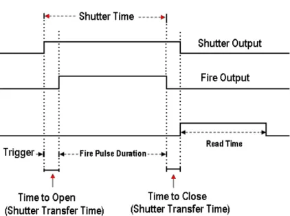
Internal In Internal Trigger Mode once an acquisition has been started via the StartAcquisition function the Andor system determines when data is actually acquired. Before the camera starts the data capture process it ensures that the CCD is in the appropriate state. This ensures that all acquisitions are identical no matter how long a time has elapsed since data was last acquired (in fact the camera continually reads out the CCD to help prevent it from being saturated by light falling on it whilst it is not acquiring data). The camera also generates all the necessary pulses for shuttering and firing external sources. These pulses are accessed directly on the camera or via the Auxiliary Connector depending on the model. The Fire Output defines the position in time during which it is safe to allow a pulsed source to fire. The figure below illustrates the timing sequence for this mode of operation.
Internal Trigger Mode is ideal for situations where you are using ‘continuous wave’ (CW) light sources (an ordinary room light for instance) and incoming data, for the purposes of your observation, are steady and unbroken: thus you can begin acquisitions ‘at will’.
You may use Internal Trigger Mode when you are able to send a trigger signal or ‘Fire Pulse’ to a short-duration, pulsed source (a laser, for example): in this case, initiating the data acquisition process can also signal the pulsed source to fire.
SDK
SECTION 5
Page 51
External In External Trigger Mode once an acquisition has been started via the StartAcquisition function the camera is placed into a special dumping version of the ‘Keep Clean’ mode, which ensures that the CCD is not saturated before the external trigger occurs. Once the External Trigger is received the Keep Clean sequence is stopped and the acquisition is initiated.
The figure below illustrates the timing sequence for this mode of operation:
The external trigger can be fed in a number of ways:
• EXT TRIG socket of the I/O Box (available separately, model #IO160)
• Pin 13 of the Auxiliary Connector on the Andor PCICard
• The head in the case of iDus / iXon.
External Trigger mode is suited to data acquisitions involving a ‘pulsed source’ (e.g. a laser) where the source does NOT allow a trigger pulse to be sent to it but can generate one. It is possible to increase the frame rate when in external trigger mode by enabling the Fast External Trigger option, see SetFastExtTrigger.
When this option is enabled the system will not wait for a Keep Clean cycle to be completed before allowing an external trigger to initiate an acquisition. This may cause the background to change from one scan to another.
NOTES:
1. If you have a shutter connected, and are using an external trigger, you must ensure that the shutter is open before the optical signal you want to measure occurs. When a camera is operated in frame transfer mode the external trigger sequence is different. Please refer to the camera user manual for a full description.
2. Some cameras may support the iCam technology. If they do, it will be fully operational in external trigger mode. It is very similar to the Software trigger functionality except that instead of a Software command instigating the acquisition, an external source does so. All the benefits described in the Software Trigger section can also be applied to the external trigger mode. It is set up in the same way with the same modes except that the trigger mode is set to External.
Frame transfer is also fully functional in iCam External Trigger mode. When Frame Transfer is on it means that the Arm signal from the camera will be enabled during the current readout at a point to ensure the next exposure will end after the current readout is finished. This will give the fastest frame rate and also ensure that the next exposure cannot end until the previous one has been readout.
SDK
SECTION 5
Page 53
External Start
In External Start Trigger Mode, once an acquisition has been started via the StartAcquisition function, the
camera system is placed into an external keep clean mode, which ensures that the CCD is not saturated before the external trigger occurs. Once the External Trigger is received, the Keep Clean sequence is stopped and the acquisition is initiated. After the initial acquisition the system will then continue to operate as in internal trigger mode. The figure below illustrates the timing sequence for this mode of operation.
External Exposure The External Exposure trigger is a mode of operation where the exposure time is fully controlled by the external trigger input. While the trigger input is high the CCD is accumulating charge in the Image area. When the external trigger goes low, the accumulated charge is quickly shifted into the Storage area and then read out in the normal manner. The figures below illustrate the timing sequences for this mode of operation.
SDK
SECTION 5
Page 55
External Exposure Trigger in Non-Frame Transfer mode
Note that not all systems support External Exposure mode. To check if this feature is available with your
system, use the function GetCapabilities and check the ulTriggerModes variable for bit 5
(AC_TRIGGERMODE_EXTERNALEXPOSURE) being set. If this bit is set, please use the function GetCapabilities again and check the ulFeatures variable for bit 12 (AC_FEATURES_FTEXTERNALEXPOSURE) being set when Frame Transfer mode is used, and bit 13 (AC_FEATURES_KINETICEXTERNALEXPOSURE) being set when Kinetc and Frame Transfer modes are used together.