IJSRSET1844266 | Received : 20 March | Accepted : 31 March 2018 | March-April-2018 [(4) 4 : 718-721 ]
718
VAR Management to Improve Maximum Loading in Standard
IEEE 30 Bus System and Allocation of STATCOM
T. Santosh Kumari1, G. Joga Rao2, Ch. Vamsi3, K. Bhaskar ,M.Raraju 4, R. C. Swamy Appalaraju5
1 Assistant Professor EEE Department, Raghu Institute of Technology, Visakhapatnam, India 2 Associate Professor EEE Department, Raghu Institute of Technology, Visakhapatnam, India 3-5 B.Tech Student EEE Department, Raghu Institute of Technology, Visakhapatnam, India ABSTRACT
The demand of electricity has become the parameter of development of a nation. An electricity utility company has to use its existing transmission capacity to feed the ever increasing demand of electricity, due to that the transmission lines has to be operated near its thermal stability limits. Operating the lines near or above thermal stability limits makes system vulnerable to faults more over it also increases the losses in the system. One way to increase the transmission capacity of the system without operating it to its thermal stability limit is to provide reactive power compensation at various locations. Reactive power compensation improves the voltage profile of the system, increase the power transfer in the lines and reduce losses in this project var compensation is processed using newton raphson method and by using the 30 bus system after successful execution of newton raphson load flow technique the amount of real power present in the bus system is modified to its maximum tolerance value. In this project we stressed statcom as the device for the compensation because of its advantages that it has in comparison with the other fact devices
Keywords : VAR, Voltage Stability, FACTS, SVC, STATCOM
I.
INTRODUCTIONThe maximum power that can be transferred over a transmission line has a limit defined by thermal limit(temperature) for very short lines and the angle or voltage stability limit for a medium and long lines. The voltage stability is related to the magnitude part of the voltage phasor on the receiving end keeping the sending voltage at a fixed value. The angle stability aspect is related to the difference in the phase angles of sending and receiving end voltages for a transmission line. e. For medium length line the inductive reactance of the line becomes predominant, absorbing the reactive part of the power, whereas the capacitive reactance contributes to surplus reactive power as the length of the line increases. There for the management of the reactive power becomes a matter of utmost importance in order to increase the
power carrying capacity of the line. The need of the reactive power desired by the transmission system can be met by the generator itself but it has got a limit imposed by the capability curves for a particular generator. so, by using FACTS and STATCOM to reduce the reactive power consumption.
II.
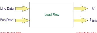
LOAD FLOW STUDIESPower-flow or load-flow studies are important for planning future expansion of power systems as well as in determining the best operation of existing systems. The principal information obtained from the power-flow study is the magnitude and phase angle of the voltage at each bus, and the real and reactive power flowing in each line.
purpose network analysers were built between 1929 and the early 1960s to provide laboratory-scale physical models of power systems. Large-scale digital computers replaced the analog methods with numerical solutions.
In addition to a power-flow study, computer programs perform related calculations such as short-circuit fault analysis, stability studies (transient and steady-state), unit commitment and economic dispatch In particular, some programs use linear programming to find the optimal power flow, the conditions which give the lowest cost per kilowatt hour delivered.
A load flow study is especially valuable for a system with multiple load centres, such as a refinery complex. The power flow study is an analysis of the system’s capability to adequately supply the connected load. The total system losses, as well as individual line losses, also are tabulated. Transformer tap positions are selected to ensure the correct voltage at critical locations such as motor control centres. Performing a load flow study on an existing system provides insight and recommendations as to the system operation and optimization of control settings to obtain maximum capacity while minimizing the operating costs. The results of such an analysis are in terms of active power, reactive power, magnitude and phase angle. Furthermore, power-flow computations
of reactive power. There are three reasons why it is necessary to manage reactive power and control voltage.
First, both customer and power-system equipment are designed to operate within a range of voltages, usually within±5% of the nominal voltage. At low voltages, many types of equipment perform poorly; light bulbs provide less illumination, induction motors can overheat and be damaged, and some electronic equipment will not operate at. High voltages can damage equipment and shorten their lifetimes.
Second, reactive power consumes transmission and generation resources. To maximize the amount of real power that can be transferred across a congested transmission interface, reactive-power flows must be minimized. Similarly, reactive-power production can limit a generator’s real-power capability.
Fig. 2 Voltage Level
B. REACTIVE POWER COMPENSATION:
load connected to the system. These inductive loads are generally electromagnetic circuit of electric motors, electrical transformers, inductance of transmission and distribution networks, induction furnaces, fluorescent lightings etc. This reactive power should be properly compensated otherwise, the ratio of actual power consumed by the load, to the total power i.e. vector sum of active and reactive power, of the system becomes quite less
This ratio is alternatively known as electrical power factor, and fewer ratios indicates poor power factor of the system. If the power factor of the system is poor, the ampere burden of the transmission, distribution network, transformers alternators and other equipments connected to the system, becomes high for required active power. And hence reactive power compensation becomes so important. This is commonly done by capacitor bank.
C. STATCOM:
STATCOM or Static Synchronous Compensator is a shunt device, which uses force-commutated power electronics (i.e. GTO, IGBT) to control power flow and improve transient stability on electrical power networks. It is also a member of the so-called Flexible AC Transmission System (FACTS) devices. The STATCOM basically performs the same function as the static VAR compensator but with some advantages.
The term Static Synchronous Compensator is derived from its capabilities and operating principle, which are similar to those of rotating synchronous compensators (i.e. generators), but with relatively faster operation.
D. FACTS:
Flexible Alternating Current Transmission System (FACTS) simply refers to a combination of power electronics components with traditional power system components. They are intended to improve our power system reliability, power transfer capability, transient and dynamic stability improvements, voltage regulation etc…
There can be series as well as shunt compensation for the transmission lines using these FACTS devices. In series compensation, line impedance is modified, that means net impedance is decreased and thereby increasing the transmittable active power. For shunt compensation, reactive current is injected into the line so as to regulate the voltage at the point of connection
F.REAL POWER VS LINE LOSSES:
III.
RESULTSThis 30 bus system is useful for practical .so the FACTS and STATCOM will give best reactive power compensation. so we obtained results of 30 bus system. It was giving the good voltage profile.
IV.
CONCLUSIONWith the increasing demand of power and slow progress on the front of installation of various types of power plants has forced power system engineers to find out means and ways to increase the loadability of transmission lines.29 and 30 respectively. Although the study a considerable improvement in the loadability of the system as a whole with FACTS, but this investigation does not consider any feasibility aspect or any kind of economic considerations involved in the installations at the FACTS controllers. Various researches have been undertaken to improve the maximum loading capacity of the transmission lines. In this paper IEEE 30 bus system with various controllers is investigated for the
parameter improvement due to SVC and STATCOM but the voltages of system with SVC are better.
V.
ACKNOWLEDGMENTWe express our thanks to the support given by management in completing our project. We express our sincere gratitude & deep sense of respect to HOD of the Electrical Department. We express our sincere thanks to our project guide Mr. T.santosh kumar Assistant Professor for his support to completion of this project. We also thankful to the teaching and non-teaching staff of Electrical department for their direct as well as indirect help in our project.
VI.
REFERENCES[1]. Hingorani N.G.,GyugyiL.2000. Understanding FACTS : Concept and technology of Flexible AC Transmission Systems, IEEE PressNew York. [2]. AchaE., FuerteC.R., AmbrizH. and AngelesC.,
FACTS :Modelling and Simulation in Power Networks, John Willey & Sons, Ltd.
[3]. PhadkeA.R., FozdarManoj,
NiaziK.R.,2012,Multi-objective fuzzy-GA formulation for optimal placement and sizing of shunt FACTS controller,” Electrical Power and Energy Systems vol.40,pp.46-53.
[4]. TomsovicK, ChowMY,2000. Tutorial on fuzzy logic applications in power systems, In: IEEE PES winter meeting, Singapore.
[5]. GaoB, MorisonGK, Kundur P,1992. Voltage stability evaluation using modal analysis, IEEE Trans Power Syst;7(4):1529–42.