Article
Conceiving Human Interaction by Visualising Depth
Data of Head Pose Changes and Emotion Recognition
via Facial Expressions
†
Grigorios Kalliatakis1,∗, Alexandros Stergiou1and Nikolaos Vidakis2
1 School of Computer Science and Electronic Engineering, University of Essex, Colchester CO4 3SQ, UK;
E-Mails: [email protected]; [email protected]
2 Department of Informatics Engineering, Technological Educational Institute of Crete, Stauromenos 71410,
Heraklion, Crete, Greece; E-Mail: [email protected]
* Correspondence: [email protected];
§ This paper is an extended version of our paper published in 8th Computer Science and Electronic Engineering (CEEC) [1].
Abstract:Affective computing in general and human activity and intention analysis in particular, is a rapidly growing field of research. Head pose and emotion changes, present serious challenges when applied to player’s training and ludology 1 experience in serious games or analysis of customer satisfaction regarding broadcast and web services or monitoring a driver’s attention. Given the increasing prominence and utility of depth sensors, it is now feasible to perform large-scale collection of three-dimensional (3D) data for subsequent analysis. Discriminative random regression forests was selected in order to rapidly and accurately estimate head pose changes in unconstrained environment. In order to complete the secondary process of recognising four universal dominant facial expressions (happiness, anger, sadness and surprise), emotion recognition via facial expressions (ERFE) was adopted. After that, a lightweight data exchange format (JavaScript Object Notation-JSON) is employed, in order to manipulate the data extracted from the two aforementioned settings. Motivated by the need of generating comprehensible visual representations from different sets of data, in this paper we introduce a system capable of monitoring human activity through head pose and emotion changes, utilising an affordable 3D sensing technology (Microsoft Kinect sensor).
Keywords: human activity analysis; affective computing; data visualisation; depth data; head pose estimation; emotion recognition
1. Introduction
Affective computing in general and human intention analysis specifically is a rapidly growing field of research, due to the constantly growing interest in applying automatic human activity analysis to all kinds of multimedia recordings involving people. Applications concerned with human activity analysis include services which support: (a) the study of player's learning and ludology experience while playing a serious game, (b) the analysis of customer satisfaction regarding broadcast and web services, and (c) the monitoring of driver's attention and concentration while commuting. Given the increasing prominence and utility of depth sensors, it is now feasible to perform large-scale collection
1
Preprints (www.preprints.org) | NOT PEER-REVIEWED | Posted: 10 July 2017 doi:10.20944/preprints201706.0003.v2
© 2017 by the author(s). Distributed under a Creative Commons CC BY license.
2 of 15
of three-dimensional (3D) data for subsequent analysis [1,2]. In this work, we focus in particular on recognising head pose and facial expression changes which can provide a rich source of information that can be used for analysing human activity in several areas of human computer interaction (HCI). Head pose estimation (HPE) refers to the process of deducting the orientation of a person's head relative to the view of a camera or to a global coordinate system. Head pose estimation is considered as a key element of human behaviour analysis. Accordingly, it has received extensive coverage in the scientific literature and a variety of techniques have been reported for precisely compute head pose [3], while depth information can also be integrated [4–6].
Facial expression is one of the most dominant, natural and instantaneous means for human beings to communicate their emotions and intentions [7]. The reason for this lies in the ability of the human face to express emotion sooner than people verbalise or even realise their feelings. Humans are able to observe and recognise faces and facial expressions in a scene with little or no effort [8]. However, development of an automated system that performs the tasks of facial expression recognition (FER) is still regarded as a rather difficult process [12]. Existing approaches in 3D FER can be typically divided into two categories: feature-based and model-based. Feature-based FER methods concentrate on the extraction of facial features directly from the input scan [9–11]. On the other hand, model-based approaches normally engage a generic face model as an intermediate for bringing input scans into correspondence by means of registration and/or dislocation [13–15].
In computer and information science, visualisation refers to the visual representation of a domain space using graphics, images and animated sequences to present the data structure and dynamic behaviour of large, complex datasets that exhibit systems, events, processes, objects and concepts. Data visualisation is a relatively new field, which not only pairs graphic design with quantitative information, but also studies humans cognitive understanding and interpretation of graphical figures, aiming at conveying data in the most efficient, but accurate and representative way [16]. In addition, visualisations can be used in several distinct ways to help tame the scale and complexity of the data so that it can be interpreted more easily.
One field that has yet to benefit of data visualisations is human intention understanding. Following Jang et al. [17], human intention can be explicit or implicit in nature. Typically, humans express their intention explicitly through facial expressions, head movements, speech, and hand gestures. Interpreting the user’s explicit intention, which contains valuable information, is vital in developing efficient human computer interfaces. In conventional human computer interface (HCI) and human robot interaction (HRI) environments, the user intention such as ‘copy this file’ or ‘create a folder’ can be explicitly conveyed through a keyboard and a computer mouse [18,19], which can be easily interpreted. The process of data visualisation is suitable for externalising the facts and enabling people to understand and manipulate the results at a higher level. Additionally, visualisations can be used in several distinct ways to help tame the scale and complexity of the data so that it can be interpreted effortlessly.
3 of 15
major part in that kind of assessment by creating encodings of data into visual channels that educators can view and understand comfortably, while they can lead to valuable conclusions regarding the overall experience of users and serious games players.
The remainder of the paper is organized as follows. The next section contains a summary of related work. Section 3 gives an overview of the adopted methods for capturing head pose and emotion changes, alongside a detailed description of our modifications for the experiments. The seven proposed web-based visualisations are presented in Section4, alongside their implementation details. Finally, Section5concludes and describes future research directions.
2. Related Work
A variety of methods have been used to represent detected emotions for research projects, as well as in the industry. However, since the results vary based on the included features, and the values that they are assigned to, a global representation method would be impracticable. Instead, the analysis produced can be delineated with a large diversity of depiction techniques.
One of the most prominent visualisation methods, with the assumption of a large quantity of experiments performed, is the use of a two dimensional line chart for a scheme of individual emotions [22]. This chart can show correlations between emotions and some patterns in the data that may be a product of common motifs in the user’s inputs(these can be translated as particular tasks/actions that cause an equivalent human reaction). In addition, the overall emotional state of the user can be monitored with a line chart, as a surge (or equivalently a decline) in the data may show a differentiation from expected values [23]. In this way, not only the dominant mood of the participant can be perceived, but also, the way that the user is emotionally effected by activities or events. Furthermore, the use of the line-chart has also focused on interpreting real-time data [24] since it can aid on the demonstration of emotion and head position constant data flow.
Another informative visualisation that complements the aforementioned line chart, and can be used in conjunction with it, is the bar chart. This mean of illustration supports a complete view of individual instances and also a general picture to be determined, based on the predicted results [25]. Bar chart allows the demonstration of the most popular emotion in addition to a complementary variable (such as the time that the data was captured or the duration of the experiment). Also, considering this additional variable, the most probable emotion can be found by taking into account the class of the categorised reactions of the users, as well as the classification confidence. Moreover, variations in values signify the possible inconsistencies of the system, alongside examples or learning tasks which may have been more difficult to be classified. For example, considering that anger and happiness are completely opposite emotions, using two distinguish bars for visualising them, expected results would only be of binary distribution, with only one bar taking above zero values (the same can also be said for head poses, for example up and down).
Regarding the representation of head pose estimations, most illustrations are targeted towards displaying the level of accuracy at each prediction and the position where the example was found to occur in a 3D or 2D chart. A good demonstration of this mindset is the use of the perspective-n-point method [26] that ‘simulates’ the view of the user’s head with a hexadecagon shape that can be rotated based on the direction of the head that was determined. However, this graphic is limited to the top view of the user’s head and therefore would only provide useful information in the case of changes in the head pose horizontally. More recent efforts have focused on 3D depiction of the user’s head position based on the pitch, roll and yaw as axis [27]. These three degrees of freedom allow to understand the position of the users head during experiments. The combination of these three values constitute each probable input head pose.
3. Overview of Methods for Capturing Head Pose and Emotion Changes
This section discuss the two methods employed in our experiments for recognising head pose and facial expressions changes, utilising an affordable 3D sensing technology (Microsoft Kinect
Preprints (www.preprints.org) | NOT PEER-REVIEWED | Posted: 10 July 2017 doi:10.20944/preprints201706.0003.v2
4 of 15
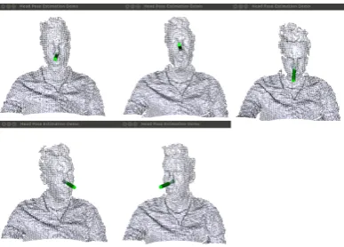
Figure 1. Some processed frames regarding two DOF (pitch and yaw), as shown by the main
application window for estimating head pose changes. Starting from left to right, the first row estimations displayed are: ‘still’, ‘up’, ‘down’. The second row estimations are ‘left’ and ‘right’ accordingly. The green cylinder encodes both the estimated head center and direction of the face.
sensor). The real-time head pose estimation and facial expression events are separately obtained for different users sitting and moving their head without restriction in front of a Microsoft Kinect sensor for specified intervals. Experimental results on 20 different users show that our modified frameworks can achieve a mean accuracy of 83.95% for head pose changes, and 76.58% for emotion changes when validated against manually constructed ground truth data.
3.1. Estimation of Head Pose Changes
Systems relying on 3D data have demonstrated very good accuracy for the task of head pose estimation, compared to 2D systems that have to overcome ambiguity in real time applications [28]. 3D head pose information drastically helps to determine the interaction between people and to extract the visual focus of attention [3]. The human head is limited to three degrees of freedom (DOF) in pose, expressed by three angles (pitch, yaw, roll) that describe the orientation with respect to a head-centered frame. Automatic and effective estimation of head pose parameters is challenging for many reasons. Algorithms for head-pose estimation must be invariant to changing illumination conditions, to the background scene, to partial occlusions, and to inter-person and intra-person variabilities. For performing the set of experiments, we partly followed the approach of Fanelli et al. [29] which is suitable for real time 3D head pose estimation, considering its robustness to the poor signal-to-noise ratio of current consumer depth cameras like Microsoft Kinect sensor. While several works in the literature contemplate the case where the head is the only object present in the field of view [30], the adopted method concerns depth images where other parts of the body might be visible at the same time, and therefore need to be disjointed into image patches either belonging to the head or not. The system is able to perform on a frame-by-frame basis while it runs in real time without the need of initialisation. Forests of randomly trained trees are less sensitive to over-fitting and generalize better than decision trees independently. In our setup, depth patches are annotated with class label and a vector:
θ=θχ,θυ,θζ,θya,θpi,θro (1)
5 of 15
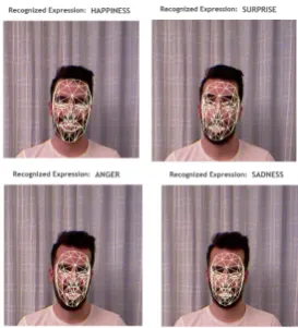
Figure 2.Facial expression recognition (FER) results.
Forests (DRRF). This signifies that an extracted patch from a depth image is sent through all trees in the forest. The patch is evaluated at each node according to the stored binary test and passed either to the right or left child until a leaf node is reached [5], at which point it is classified. Only if this classification outcome is positive (head leaf), a Gaussian distribution is recaptured and then used for casting a vote in a multidimensional continuous space which is stored at the leaf. Figure1shows some processed frames regarding two DOF (pitch and yaw). All calculations derived from the difference between the exact previous frame and the current frame, at each iteration of the experiment. The green cylinder encodes both the estimated head center and direction of the face.
pitchDi f f = pitcht−1−pitcht (2)
yawDi f f =yawt−1−yawt (3)
up=pitchDi f f >THRESH1 (4)
down=pitchDi f f <THRESH1 (5)
le f t=yawDi f f >THRESH2 (6)
right=yawDi f f <THRESH2 (7)
Our aim is to capture all the changes concerning pitch and yaw angles which occur during the experiments. For this reason, given the pitch (pitcht) and yaw (yawt) intensities of the ongoing
streaming frame, and the exact previous frame's pitch (pitcht−1) and yaw (yawt−1) intensities, the
system operates in three steps as follows: (a) the differences regarding pitch and yaw are calculated by Equations (2) and (3) ; (b) then two different threshold values were experimentally set in order for our system to ignore negligible head movements in the two DOF tested; (c) finally, the changes with respect to the four different directions are given by Equations (4) to (7) .
3.2. Emotion Recognition from Facial Expressions
Emotion recognition via facial expressions (ERFE), is a growing research field in computer vision compared to other emotion channels, such as body actions and speech, primarily because superior expressive force and a larger application space is provided. Features which are utilised to classify human affective states, are commonly based on local spatial position or dislocation of explicit points and regions of the face. Recognition of facial action units (AU) is one of the two main streams in facial expression analysis. AUs are anatomically related to the reduction of specific facial muscles, 12 for upper face and 18 for lower face [31]. A total of 44 AUs can be derived from the face, and their combinations can compose different facial expressions. In this work, 4 basic universal expressions
Preprints (www.preprints.org) | NOT PEER-REVIEWED | Posted: 10 July 2017 doi:10.20944/preprints201706.0003.v2
6 of 15
are considered: happiness, surprise, sadness and anger. An approach similar to Mao et al. [32] was followed for real time emotion recognition. Video sequences acquired from the Kinect sensor are regarded as input. The Face Tracking SDK [33], which is included in Kinect’s Windows Developer toolkit, is used for tracking human faces with RGB and depth data captured from the sensor. Face detection and feature extraction are performed on each frame of the stream. Furthermore, facial animation units and 3D positions of semantic facial feature points can be computed by the face tracking engine, which can lead to the aforementioned emotion recognition via facial expressions. Face tracking results are expressed in terms of weights of six animation units, which belong to a subset of what is defined in the Candide3 model [34]. Each AU, that is deltas from the neutral shape, is expressed as a numeric weight varying between−1 and +1, and the neutral states of AUs are normally assigned to 0. Utilising Equation (8) , the AU's feature of each frame can be written in the form of a 6-element vector :
¯
a= (A1,A2,A3,A4,A5,A6) (8)
where A1, A2, A3, A4, A5, and A6 refer to the weights of lip raiser, jaw lower, lip stretcher, brow lower,lip corner depressor, andbrow raiser, respectively. Boundaries for each AU had to be empirically established in order to associate the vector obtained by the AU feature, as defined by (1), with the four main emotions considered in this paper. For example, (0.3, 0.1, 0.5, 0,−0.8, 0) corresponds to a happy face, which means showing teeth slightly, lip corner raised and stretched partly, and the brows are in the neutral position. Equations (9) to (12) were experimentally formulated for the test sessions. An example of all four different recognised emotions is shown in Figure2.
sadness=A6<0∧A5>0 (9)
surprise= (A2<0.25∨A2>0.25)∧A4<0 (10)
hapiness=A3>0.4∨A5<0 (11)
anger= ((A4>0∧(A2>0.25∨A2<−0.25)∨(A4>0∧A5>0)) (12)
3.3. Data Compilation and Experimental Setup
Regarding the storage of the obtained data, JavaScript Object Notation (JSON) format was used mainly because of its lightweight nature, convenience in writing and reading and more importantly, as opposed to other formats such as XML, its suitability in generating and parsing tasks in various Ajax applications as described in [35]. A record in an array was created for each user session, while an extra array was inside it, carrying three variables:time,directionandintensityfor each movement that was detected. For facial expressions, a similar array was created, but in this case only two variables were listed:timeandemotion
7 of 15
29/05/2017 83.212.117.19/HeadPoseScatterplot/
http://83.212.117.19/HeadPoseScatterplot/ 1/1
Player Movement vs Time Graph
0.0 0.5 1.0 1.5 2.0 2.5 3.0 3.5 4.0 4.5 5.0 5.5 6.0 6.5 7.0 7.5 8.0 8.5 9.0 9.5 10.0 10.5 11.0 11.5 12.0 12.5 13.0 13.5 14.0 14.5 15.0 15.5 16.0 16.5 17.0 17.5 18.0 18.5 19.0 19.5 20.0 20.5 21.0 21.5 22.0 Player 1
Player 2 Player 3 Player 4 Player 5 Player 6 Player 7 Player 8 Player 9 Player 10 Player 11 Player 12 Player 13 Player 14 Player 15 Player 16 Player 17 Player 18 Player 19 Player 20 Player 21
Time (sec)
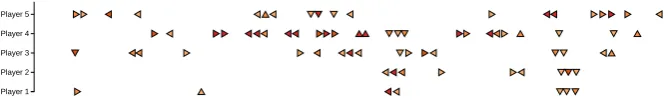
Figure 3. Scatterplot visualisation of head pose changes. Four different arrows imitate the head
movement for two DOF. Colour fluctuation serves as intensity indicator for each movement (the closer to red color the arrow is, the higher the intensity of the movement).
4. Visualisations on the Web
Although many different approaches have been proposed in the literature to solve the problem of recognising head pose and emotion changes, very few focus on how those data can be presented in order to deliver a useful interpretation effortlessly. To that end, the principal objective of this section is to introduce various efficient and user-friendly web-based visualisations2in order to improve the understanding and the analysis of human activity from the captured data of head pose and emotion changes.
4.1. Representative Scenario
To illustrate some of the concepts described thus far and to provide insight into the technical features of our web-based visualisations, we will briefly describe a representative scenario emphasising on the effortless data interpretation they present. Our reference scenario is summarised in Exhibit 1.
Exhibit 1: Charlie who is responsible for teaching young people through educational and training games, wants to organise a session for his students. He also wants to monitor his students emotions throughout the whole duration of the session separately from the main game to boost his chances of recognising when his students were facing difficulties or when his students were achieving some goals in the context of the game he had previously designed. However, as he is interested in drawing valuable conclusions regarding the overall ludology experience of the players, he has to analyse those findings.
Motivated by those needs, our system is not only capable of monitoring human activity through head pose changes and emotion recognition, but also to visually depict those data in order to enable educators to understand and manipulate the results at a higher level from the convenience of a website.
4.2. Head Pose
Four different visualisations are established for the desirable web-based data interpretation of head pose changes in Figures 3, 6, 8 and 9. The first one is a 2D scatterplot displaying the head movement of the user over specified time period. After that, a column visualisation depicting the overall head pose changes grouped by their dominant direction is presented. Finally, an intensity chart and a pie chart for outlining the intensities of head pose changes and their proportions in terms of the dominant direction are shown.
Preprints (www.preprints.org) | NOT PEER-REVIEWED | Posted: 10 July 2017 doi:10.20944/preprints201706.0003.v2
8 of 15 N u m b er o f M ov em en ts
Total players' movement, grouped by direction
UP DOWN LEFT RIGHT
0-2 sec 2-4 sec 4-6 sec 6-8 sec 8-10 sec 10-1 2 se
c
12-1 4 se
c
14-1 6 se
c
16-1 8 se
c
18-2 0 se
c 0 5 10 15 20 25 30 35 40 45 50 55
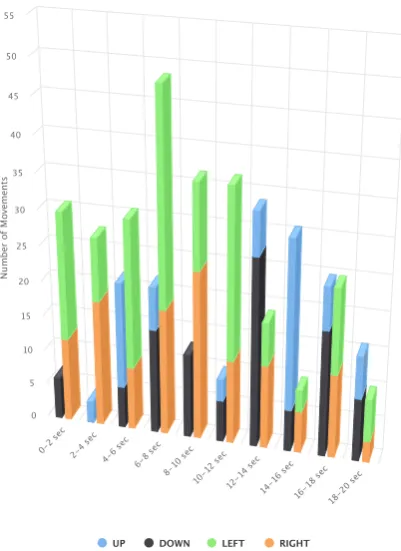
Figure 4.Column visualisation of head pose changes.
4.2.1. Head Pose Changes Across Time
Regarding the two-dimensional scatterplot, x-axis represents the time scale in seconds during which the tests take place (Figure3 shows only a zoomed portion of the whole graph), while each label in y-axis symbolises each different user performing the test. Four different arrows imitate the movement of the human’s head in two DOF. Furthermore, an additional feature is displayed when the mouse hangs over an arrow, showing the respective time each movement occurred and the intensity, which derives from the difference between the previous and the current frame was, as explained in Section3.1. Apart from those elements, a colour fluctuation is also evident which serves as an intensity indicator for each movement (the closer to red color the arrow is, the higher the intensity of the movement). One can easily examine the motion of the player that way, alongside its intensity, which adds a different dimension to the knowledge gained from the visualisation. The chart clearly saws to Charlie (see representative scenario) that almost all his students around second 12-14 look down which could be interpreted to player being bored with the game at this specific moment. Charlie could then examine the game at the specific moment and enhance it to avoid the students filling of boredom. The full version of this visualisation is available at:
http://83.212.117.19/HeadPoseScatterplot/.
4.2.2. Head Pose Changes Grouped by Direction
9 of 15
Figure 5.Intensity chart with time intervals clustered and displayed as labels.
number of movements for all the users that take part in the tests. Furthermore, when hovering above a column, the number of the corresponding direction summary is displayed. In this fashion, the dominant direction amongst all users every time interval is effortlessly assumed. Moreover, not so evenly distributed movements (e.g. columns between 2- 4 seconds in Figure 4) can lead into practical conclusions taking into account the nature of the test as well. Figure 4 confirms that the majority of Charlie's students look down (finding of visualisation at Figure3) as the black colour is the dominant color at the time range 12-14 seconds. This second visualization affirms the assumption of something must be changed around game play time second 12-14 and that Charlie must pay attention to it. The full version of the overall head movement visualisation is available at:
http://83.212.117.19/HeadPose3D/.
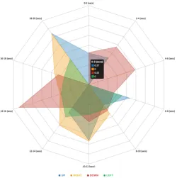
4.2.3. Intensities of Head Pose Changes
As mentioned before, the duration of the experiment can be an important aspect of the observations, as examples can be over-represented or under-represented in particular times during the tests. For this reason, an additional visualisation technique is used to exhibit any differences and inconsistencies. Considering these requirements, the best approach was the use of a intensity chart with the construction of a decagon, with each edge representing the different time values of the experiments, as shown in Figure5.
This grid can display the movements that were classified by the system based on a time interval and also their average intensity at that time. Each edge of the decagon represents the average integer value (or the mean as well in this case) of each class. To emphasise on further user-interaction with the page, once the cursor hovers over one of the ten rectangles, a small legend appears holding additional information for the movement that was found. The legend holds the four labels present, as well as the precise intensity of each event in that period (up to the two most important floating points). These rectangles can be defined as the shape produced by the two halves of two consecutive sides, by the two radius from the centre of the shape to the end-points of the side-halves. In case of missing examples between two observations that are separated by a class with a reasonable amount of information, the class is displayed as a line from the centre of the shape until the related intensity
Preprints (www.preprints.org) | NOT PEER-REVIEWED | Posted: 10 July 2017 doi:10.20944/preprints201706.0003.v2
10 of 15
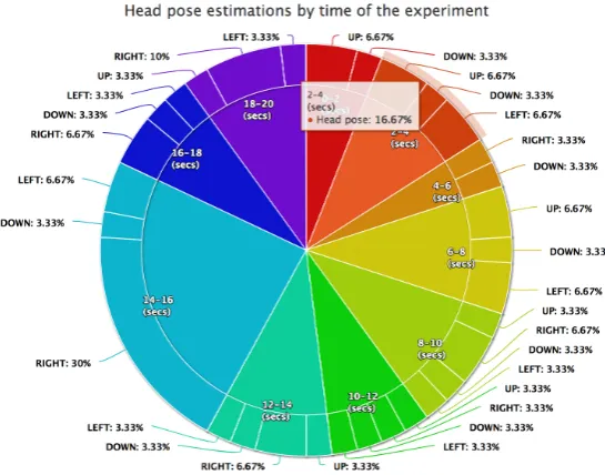
Figure 6.Two-layer pie chart with time intervals clustered and displayed as labels in the centred pie
and the recognised head pose population percentages at the external layer.
is reached. This is done in order to indicate that there is no relation between the previous and the next class, since no examples of those two time-slots are present in the data. The shape as well as the legend are dynamically generated by the system and therefore can be manipulated if different data are to be used, as well as classes. The visualisation of Figure 5 also illustrates that the majority of Charlie's students around second 14 look down. With this specific visualisation Charlie also easily notices that seconds 3, 4, 5 and 6 might be subject to further investigation regarding game ludology. The full version of the overall head movement visualisation is available
at:http://83.212.117.19/IntensityGrid/.
4.2.4. Head Pose Changes Grouped by Proportion of the Direction
Another widely used visualisation is the pie chart. In order to accommodate both attributes of our experiments (time in seconds and the head pose direction estimated), the pie consists of two layers, as shown in Figure6. This structure allows a broader view of the experiments and the data since a batch of variables is used instead of a single one. The internal circle consists of the time classes as been determined in previous illustrations as well. The information presented to the user at this level, is primarily focused towards the distribution of the data based on the experiment durations. Durations that are centred around smaller values are expected to hold larger confidence than others with larger time values. Therefore, when analysing the shape produced, the user would prefer to see a high concentration of short time examples. The external circle consists of the recognition directions that each internal time class includes. Also, if experiments do not hold any examples of a head pose, this will be shown in the chart. In addition to examples that were not present in the class, this visualisation can furthermore show over-represented or under-represented examples in a similar way as the emotion detection punchcard (Figure7). With this visualisation Charlie can easily observe that seconds 14-16 might be subject to further investigation regarding game ludology. The full version of the overall head movement visualisation is available at:http://83.212.117.19/PieChart/.
4.3. Emotions
11 of 15
2017-5-29 index.html
file:///Users/alexandrosstergiou/Desktop/Resources/Code/Emotion%20detection%20-%20punchcard/index.html 1/1 11 May 2015
12 May 2015
13 May 2015
14 May 2015
15 May 2015
16 May 2015
17 May 2015
18 May 2015
19 May 2015
20 May 2015
0-2 2-4 4-6 6-8 8-10 10-12 12-14 14-16 16-18 18-20
Experiment time intervals (secs) Consecutive days of identical intreval, conditions & emotions for each experiment
Happiness
Sadness
Surprise
Anger
Sadness/Anger
Neutral
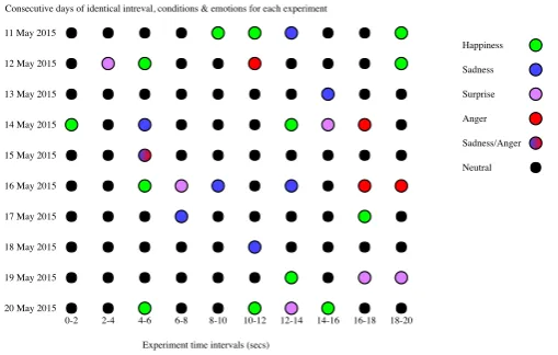
Figure 7.Punch-card table based on time and date of experiment
a punch-card table is presented in order to represent emotion changes across the time intervals of our experiments. After that, a column visualisation depicting the overall facial expression changes grouped by the resulting emotion is presented. Finally, emotions grouped by specific time intervals are illustrated in the form of a class connection circle.
4.3.1. Emotion Changes Across Time
A straightforward way of representing the emotions detected by the main system in comparison to the date and duration of the experiment is the use of a two dimensional punch-card. The y-axis of the card is used to set the epoch of each experiment, while the x-axis specifies the duration that the experiment was conducted as time intervals, as shown in Figure7. This allows the users to find the total number of tests that were carried out at a specified date, but also the order in which these experiments were conducted. The outcomes of the experiments ranged across four main classes (happiness, sadness, surprise and anger) with an additional ‘combination’ class which was used to represent the recognition of emotions in a pair (sadness and anger). Since this approach utilises the capabilities of data representation in 2D-space, a viewer can furthermore find the times that most observations occurred in the data provided.
The reason behind the choice of punch-card table is the fact that the user’s emotions can be tracked through time and also motifs can emerge from the data. For example, by observing the punch-card it can be found which pairs of emotions are probable to occur together or are expected to be found. With the combination of the data about the tasks or actions preformed by the user, possible future emotional reactions can be predicted on related tasks. These patterns can be an essential part of the recognition process in a way that, they can show the emotion(s) that can be expected for a user to display at a particular time period and by performing a specific action, taking to account the previous emotion distributions. Furthermore, with respect to the task/event that was carried out by the user during an experiment, emotions that cause a large variation in the emotional state of the person, can be interpreted by the system and visualised as how the person reacts to the occasion.
Moreover, if a combination of emotions is detected for a distinct experiment date, the data is shown as a gradient of the two emotions. This is done to distinguish (as it is also achieved by the bar chart) the cases in which the method used produces poor-correlation results. Therefore, if the recognition process produces a dual emotion class in which the two combinational emotions are not sufficiently related, to a certain degree, it could be interpreted as a poor choice of recognition methods. The Punch-card table visualisation shows that at second 14, 50%-70% have neutral feelings, 10%-20% feel sad, 10% feel surprised and 10%-20% feel happy. Thus Charlie's students show practically very low interest at the game or feel sad about it. Only a small number feels happy. Charlie, by combining knowledge gained from the head pose visualisations and the emotion change
Preprints (www.preprints.org) | NOT PEER-REVIEWED | Posted: 10 July 2017 doi:10.20944/preprints201706.0003.v2
12 of 15 N u m b e r o f F a ci a l E x p re ss io n s
Total players' facial expression, grouped by emotion
HAPPINESS SADNESS SURPRISE ANGER
0-2 sec 2-4 sec 4-6 sec 6-8 sec 8-10 sec 10-1 2 se
c 12-1
4 se c
14-1 6 se
c 16-1
8 se c
18-2 0 se
c 0 1 2 3 4 5 6 7 8 9 10 11 12 13
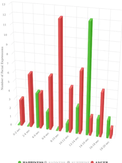
Figure 8.Column visualisation of two detected emotions, ‘happiness’ and ‘anger’
visualisations can safely assume that head pose down means very limited interest at the game. These type of knowledge provide Charlie the necessary means to enhance his educational games, i.e. his professional applications. The full version of the emotion changes across time visualisation is available at:http://83.212.117.19/PunchCard/.
4.3.2. Facial Expressions Grouped by Emotion
The second visualisation consists of a column diagram (similar to the one used for head pose changes in Figure4) which illustrates the aggregation of all facial expressions grouped by the resulting emotions for every two seconds. Figure8displays only two emotions, happiness and anger. However the rest of the recognised emotions can be set visible by clicking the corresponding check-box. The four different emotions are represented by four different colours. In one hand, x-axis represents the time scale which is divided every two seconds until the end of the test. On the other hand, y-axis displays the number of recognised emotions for all the users that take part in the tests. Furthermore, when hovering above a column, the number of the corresponding emotion summary is displayed. Figure 8 shows that Charlie's students at game time range 10-12 feel angry. The visualization is not exactly in line with the rest of the visualisations as it shows negative feelings 2 seconds before. Nevertheless, the time difference of 2 seconds is considered minimal and Charlie can safely draw his assumption about, the game, the head pose meaning and the emotions changes while students play his educational game. The full version of the visualisation concerning facial expressions grouped by emotion is available at:http://83.212.117.19/FacialExpression3D/.
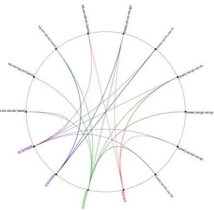
4.3.3. Emotions Grouped by Time Intervals
13 of 15
2017-5-24 Circlular emotion detection visualisation
file:///Users/alexandrosstergiou/Desktop/Resources/Visualizations/Emotion%20Detection%20Intensity%20circle/index.html 1/1
Circlular emotion detection visualisation
Figure 9.Circular emotion detection results based on the duration of the experiments ans segmented
to time classes with a fixed class margin of two
between the point that holds the time class in interest and the emotion assigned to it. The final graph produced by the process depicts the association between the durations and the emotions that were recognised at the time of the experiments.
This visualisation was implemented as an additional method for the emotion punch-card as the correlation between emotions could not be fully interpreted in that case. By combining these two illustration techniques, a possible user can have a wider view not only of the emotions recognised based on specific time intervals, but also how the emotions and durations of the experiments are correlated. The most essential information piece that can be portrayed in this graph is how different emotion classes coexist with time classes. This allows the user to understand if a particular incident occurring at a specific time (considering the fact that the data comes for identical experiments performed at each date), would have a positive or negative effect on the psychology of the person and the way that this will transpire. For example, taking the 06.00 to 08.00 class, it is clear that the two emotions recorded, are related to negative/unpleasant emotions since the user was identified to be angry and surprised. Though the constant observation of the sentiments and the order they have been conducted in different durations, a general estimation of human reactions can be drawn based on the event that the person participated in the example was exposed to. In addition, the lines connecting the two points can also be viewed as the links between the durations and the emotions, and if the intensity is required to be shown as well, the line’s colour may be based on a variable that is to determined in relation to the experiment’s intensity. Figure9confirms that the majority of Charlie's students mostly feel sad at the game time range 12-14 seconds. This visualization affirms the assumption that head pose dawn represents a negative player-student-user feeling and that something must be changed around game play time second 12-14 in order for Charlie to enhance user experience. The full version of the emotions grouped by time intervals visualisation is available
at:http://83.212.117.19/IntensityCircle/.
5. Conclusions and Future Work
To advance the field of human activity analysis, we need mechanisms capable of externalising the facts and enabling people to manipulate the findings of human activity monitoring tasks at a higher level. In this work, we propose seven different web-based visualisations that can help tame the scale and complexity of the depth data collected for the purpose of monitoring head pose and
Preprints (www.preprints.org) | NOT PEER-REVIEWED | Posted: 10 July 2017 doi:10.20944/preprints201706.0003.v2
14 of 15
emotion changes. All visualisations, and other data, as well as the source code, are publicly available online.
Interesting future direction will be to investigate real-time fusion of the two frameworks, while future works include going beyond basic player monitoring to study if the actions taken by an educator have resulted in further changes in the mood of the players, in the context of serious game. Another direction would be to to analyse if the aforementioned mood changes would produce different results in the performance of the players. Finally, an evaluation of all different visualisations presented in this article is in our immediate research plans.
Author Contributions: Grigorios Kalliatakis and Nikolaos Vidakis conceived and designed the experiments;
Grigorios Kalliatakis performed the experiments and analysed the results, whereas Alexandros Stergiou contributed to the design and analysis of the proposed visualisations. Grigorios Kalliatakis, Alexandros Stergiou and Nikolaos Vidakis wrote the paper. All authors contributed to the discussion and revision of the manuscript.
The authors declare no conflict of interest.
Bibliography
1. G. Kalliatakis, N. Vidakis and G. Triantafyllidis, Web-based visualisation of head pose and facial expressions changes: Monitoring human activity using depth data, 2016 8th Computer Science and Electronic Engineering (CEEC), Colchester, 2016, pp. 48-53. doi: 10.1109/CEEC.2016.7835887.
2. Grigorios Kalliatakis, Georgios Triantafyllidis, and Nikolaos Vidakis. 2015. Head pose 3D data web-based visualization. In Proceedings of the 20th International Conference on 3D Web Technology (Web3D ’15). ACM, New York, NY, USA, 167-168. doi: http://dx.doi.org/10.1145/2775292.2778304.
3. E. Murphy-Chutorian and M. M. Trivedi. Head Pose Estimation in Computer Vision: A Survey. IEEE Transactions on Pattern Analysis and Machine Intelligence, 2009, 31, 607-626, doi: 10.1109/TPAMI.2008.106. Available onlinehttp://ieeexplore.ieee.org/stamp/stamp.jsp?tp=&arnumber= 4497208&isnumber=4785439(accessed on 30 May 2017).
4. M. D. Breitenstein, D. Kuettel, T. Weise, L. van Gool and H. Pfister. Real-time face pose estimation from single range images, 2008 IEEE Conference on Computer Vision and Pattern Recognition, Anchorage, AK, 2008, pp. 1-8. doi: 10.1109/CVPR.2008.4587807.
5. G. Fanelli, J. Gall and L. Van Gool. Real time head pose estimation with random regression forests, CVPR 2011, Providence, RI, 2011, pp. 617-624. doi: 10.1109/CVPR.2011.5995458.
6. P. Padeleris, X. Zabulis and A. A. Argyros. Head pose estimation on depth data based on Particle Swarm Optimization, 2012 IEEE Computer Society Conference on Computer Vision and Pattern Recognition Workshops, Providence, RI, 2012, pp. 42-49. doi: 10.1109/CVPRW.2012.6239236.
7. Yuwen Wu, Hong Liu and Hongbin Zha, Modeling facial expression space for recognition. 2005 IEEE/RSJ International Conference on Intelligent Robots and Systems, 2005, pp. 1968-1973. doi: 10.1109/IROS.2005.1545532.
8. Jain, Anil K., and Stan Z. Li. Handbook of face recognition. New York: springer, 2011.
9. Xue, Mingliang, Ajmal Mian, Wanquan Liu, and Ling Li. Fully automatic 3D facial expression recognition using local depth features, 2014, in Applications of Computer Vision (WACV), IEEE Winter Conference, pp. 1096-1103.
10. Azazi, Amal, Syaheerah Lebai Lutfi, and Ibrahim Venkat. Analysis and evaluation of SURF descriptors for automatic 3D facial expression recognition using different classifiers, 2014 in Information and Communication Technologies (WICT), 2014 Fourth World Congress on, pp. 23-28.
11. Kim, Bo-Kyeong, Jihyeon Roh, Suh-Yeon Dong, and Soo-Young Lee. Hierarchical committee of deep convolutional neural networks for robust facial expression recognition, 2016 Journal on Multimodal User Interfaces 2, no. 10: 173-189.
12. Fang, Tianhong, Xi Zhao, Omar Ocegueda, Shishir K. Shah, and Ioannis A. Kakadiaris. 3D facial expression recognition: A perspective on promises and challenges, 2011 In Automatic Face & Gesture Recognition and Workshops (FG 2011), 2011 IEEE International Conference on, pp. 603-610. IEEE.
15 of 15
14. Siddiqi, Muhammad, Rahman Ali, Adil Khan, Eun Kim, Gerard Kim, and Sungyoung Lee. Facial expression recognition using active contour-based face detection, facial movement-based feature extraction, and non-linear feature selection, 2015 Multimedia Systems 21, no. 6 .
15. Fang, Tianhong, Xi Zhao, Omar Ocegueda, Shishir K. Shah, and Ioannis A. Kakadiaris. 3D/4D facial expression analysis: An advanced annotated face model approach, 2012 Image and vision Computing 30, no. 10: 738-749.
16. Mulrow, Edward J. The visual display of quantitative information. (2002): 400-400.
17. Young-Min Jang, Rammohan Mallipeddi, Sangil Lee, Ho-Wan Kwak, Minho Lee, Human intention recognition based on eyeball movement pattern and pupil size variation, Neurocomputing, 2014, 128, 421-432, doi: https://doi.org/10.1016/j.neucom.2013.08.008. Available onlinehttp://www.sciencedirect. com/science/article/pii/S0925231213008795(accessed on 30 May 2017).
18. Youn, So-Jeong, and Kyung-Whan Oh. Intention recognition using a graph representation. World Academy of Science, Engineering and Technology 25,2007, 13-18.
19. Vidakis, Nikolas, Anastasios Vlasopoulos, Tsampikos Kounalakis, Petros Varchalamas, Michalis Dimitriou, Gregory Kalliatakis, Efthimios Syntychakis, John Christofakis, and Georgios Triantafyllidis. Multimodal desktop interaction: The face-object-gesture-voice example. In Digital Signal Processing (DSP), 2013 18th International Conference on, pp. 1-8. IEEE, 2013.
20. Vidakis, Nikolas, Efthymios Syntychakis, Kostantinos Kalafatis, Eirini Christinaki, and Georgios Triantafyllidis. Ludic Educational Game Creation Tool: Teaching Schoolers Road Safety. In International Conference on Universal Access in Human-Computer Interaction, pp. 565-576. Springer International Publishing, 2015.
21. Vidakis, Nikolas, Eirini Christinaki, Iosif Serafimidis, and Georgios Triantafyllidis. Combining ludology and narratology in an open authorable framework for educational games for children: the scenario of teaching preschoolers with autism diagnosis. In International Conference on Universal Access in Human-Computer Interaction, pp. 626-636. Springer International Publishing, 2014.
22. Schurgin, M. W., J. Nelson, S. Iida, H. Ohira, J. Y. Chiao, and S. L. Franconeri. Eye movements during emotion recognition in faces. Journal of Vision 14, no. 13 (2014): 14-14.
23. Salgado, António. The facial and vocal expression in singers: a cognitive feedback study for improving emotional expression in solo vocal music performance. Electronic Musicological Review 9,2005.
24. Neidle, Carol, Jingjing Liu, Bo Liu, Xi Peng, Christian Vogler, and Dimitris Metaxas. Computer-based tracking, analysis, and visualization of linguistically significant nonmanual events in American Sign Language (ASL). In LREC Workshop on the Representation and Processing of Sign Languages: Beyond the Manual Channel, vol. 5. 2014.
25. Patwardhan, Amol. Edge Based Grid Super-Imposition for Crowd Emotion Recognition. International Research Journal of Engineering and Technology (IRJET),2016, 3, 459-463
26. Alioua, Nawal, Aouatif Amine, Abdelaziz Bensrhair, and Mohammed Rziza. Estimating driver head pose using steerable pyramid and probabilistic learning. International Journal of Computational Vision and Robotics 5,2015, 4, 347-364.
27. Vatahska, Teodora, Maren Bennewitz, and Sven Behnke. Feature-based head pose estimation from images. In Humanoid Robots, 2007 7th IEEE-RAS International Conference on, pp. 330-335. IEEE, 2007.
28. Kalliatakis Grigorios. Towards an automatic intelligible monitoring of behavioral and physiological metrics of user experience: head pose estimation and facial expression recognition. Master of Science, Department of Applied Informatics and Multimedia, School of Applied Technology, Technological Educational Institute of Creece, August 2015.
29. Fanelli, Gabriele, Thibaut Weise, Juergen Gall, and Luc Van Gool. Real time head pose estimation from consumer depth cameras. In Joint Pattern Recognition Symposium, pp. 101-110. Springer Berlin Heidelberg, 2011.
30. Fanelli, Gabriele, Matthias Dantone, Juergen Gall, Andrea Fossati, and Luc Van Gool. Random forests for real time 3d face analysis. International Journal of Computer Vision 2013, 101, 437. doi:10.1007/s11263-012-0549-0. Available onlinehttp://dx.doi.org/10.1007/s11263-012-0549-0(accessed on 30 May 2017).
31. Tian, Y-I., Takeo Kanade, and Jeffrey F. Cohn. Recognizing action units for facial expression analysis. IEEE Transactions on pattern analysis and machine intelligence 23, no. 2 (2001): 97-115.
Preprints (www.preprints.org) | NOT PEER-REVIEWED | Posted: 10 July 2017 doi:10.20944/preprints201706.0003.v2
16 of 15
32. Mao, Qi-rong, Xin-yu Pan, Yong-zhao Zhan and Xiang-jun Shen. Using Kinect for real-time emotion recognition via facial expressions. Frontiers of Information Technology and Electronic Engineering 16 (2015): 272-282.
33. Microsoft, Face Tracking SDK documentation. Available online: https://msdn.microsoft.com/en-us/ library/jj130970.aspx(accessed on 30 May 2017).
34. Ahlberg, Jörgen. Candide-3-an updated parameterised face. (2001).