IJEDR1802124
International Journal of Engineering Development and Research (
www.ijedr.org
)
671
Equation for Deflection in a Hollow Bar with
Continuously Varying Rectangular Cross Section:
Validation Using Ansys 13.0
B Vishwash Assistant Professor
Department of Mechanical Engineering
Siddaganga Institute of Technology, Tumakuru, Karnataka, India
_____________________________________________________________________________________________________
Abstract — In this paper an equation for deflection in a hollow bar with continuously varying rectangular cross section
has been developed. The developed equation is a new equation and can be reduced to the equation of deflection for solid tapered bar with continuously varying rectangular cross section. The developed equation has been validated using the ANSYS solution. The validation is done by assuming the values for the variables and obtaining deflection value for the bar using both developed equation and ANSYS. The obtained values are compared and the developed equation is validated. The equation is found to be correct and can be used directly to obtain the deflection in the hollow tapered bar with continuously varying rectangular cross sections.
Index Terms — Bar, Beam, Deflection, Finite Element Model (FEM) and ANSYS.
_____________________________________________________________________________________________________
I. INTRODUCTION
The deflection distance of a member under a load is directly related to the slope of the deflected shape of the member under that load, and can be calculated by integrating the function that mathematically describes the slope of the member under that load. Deflection can be calculated by standard formula by methods such as virtual work, direct integration, Castigliano's method, Macaulay's method or the direct stiffness method, etc [1-6]. The deflection of beam elements is usually calculated on the basis of the Euler–Bernoulli beam equation while that of a plate or shell element is calculated using plate or shell theory which holds good for all types of cross sections [6-12]. But there is no specific theory for the deflection of bars, based on which the deflection can be calculated and which holds good for all types of cross sections [13-15]. In this paper an equation for the deflection of the tapering bar with continuously varying rectangular cross section has been developed. The developed equation has been validated by comparing the deflection value obtained by the developed equation with the ANSYS solution for different assumed values of variables. The paper is organised as follows. In section 1 introduction is given, section 2 gives the developed equation, section 3 gives the calculation of the deflection values, section 4 gives the ANSYS solution and section 5 gives conclusions followed by references.
II. EQUATIONFORDEFLECTION
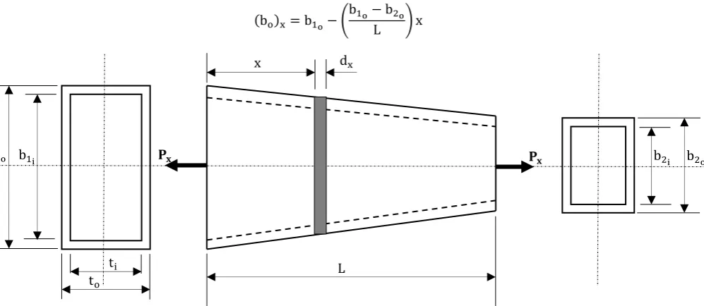
Consider a hollow bar of continuously varying rectangular cross section as shown in Figure 1. Let L be the length of the tapered bar, ti be the inner thickness of the bar, to be the outer thickness of the bar and Px be axial force acting on the bar. The hollow bar tapers from the outer breadth b1o at length = 0 to b2o at length = L. Similarly, the hollow bar tapers from the inner breadth b1i at length = 0 to b2i at length = L.
Rate of change of inner breadth,
(bi)R=
b1i− b2i L Rate of change of outer breadth,
(bo)R=
b1o− b2o L
Consider an elemental length dx at a distance x from larger end as shown in Figure 1.
Hence,
Inner breadth at section at x is
(bi)x= b1i− (
b1i− b2i L ) x
IJEDR1802124
International Journal of Engineering Development and Research (
www.ijedr.org
)
672
(bo)x= b1o− (b1o− b2o L ) x
Figure 1: Hollow tapered bar with continuously varying rectangular cross section
Therefore,
Outer rectangular cross sectional area of the section at x is
(Ao)x= to(bo)x= to[b1o− (
b1o− b2o L ) x]
Inner rectangular cross sectional area of the section at x is
(Ai)x= ti(bi)x= ti[b1i− (
b1i− b2i L ) x]
Area of the hollow rectangular section at x is
Ax= (Ao)x− (Ai)x
Ax= {to[b1o− (
b1o− b2o
L ) x]} − {ti[b1i− (
b1i− b2i L ) x]}
Extension of the hollow rectangular section at x is given by, δ =Pxdx
AxE
δ = Pxdx
{{to[b1o− (
b1o− b2o
L ) x]} − {ti[b1i− (
b1i− b2i L ) x]}} E
δ = Pxdx
{[tob1o− to(b1o− b2o
L ) x] − [tib1i− ti(
b1i− b2i L ) x]} E
δ = Pxdx
[tob1o− to(
b1o− b2o
L ) x − tib1i+ ti(
b1i− b2i L ) x] E
δ = Pxdx
{(tob1o− tib1i) + [ti(
b1i− b2i L ) − to(
b1o− b2o L )] x} E
Hence,
Total extension of the tapered hollow rectangular bar is,
∆=Px E∫
dx
{(tob1o− tib1i) + [ti(
b1i− b2i L ) − to(
b1o− b2o L )] x} L
0
b1i 𝐏𝐱 𝐏𝐱 b2i
b1o b2o
to
ti L
IJEDR1802124
International Journal of Engineering Development and Research (
www.ijedr.org
)
673
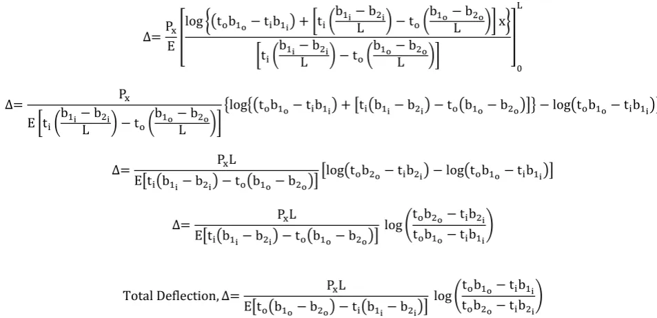
∆=PxE[
log {(tob1o− tib1i) + [ti(
b1i− b2i L ) − to(
b1o− b2o L )] x}
[ti(
b1i− b2i L ) − to(
b1o− b2o L )]
]
0 L
∆= Px
E [ti(
b1i− b2i L ) − to(
b1o− b2o L )]
{log{(tob1o− tib1i) + [ti(b1i− b2i) − to(b1o− b2o)]} − log(tob1o− tib1i)}
∆= PxL
E[ti(b1i− b2i) − to(b1o− b2o)][log(tob2o− tib2i) − log(tob1o− tib1i)]
∆= PxL
E[ti(b1i− b2i) − to(b1o− b2o)] log (
tob2o− tib2i tob1o− tib1i )
Total Deflection, ∆= PxL
E[to(b1o− b2o) − ti(b1i− b2i)] log (
tob1o− tib1i tob2o− tib2i )
The above equation is the equation for deflection in a hollow tapered bar with continuously varying rectangular cross section. This equation can be reduced to get the deflection for a solid bar of continuously varying rectangular cross section as given in [1] by substituting ti= 0, b1i = 0 and b2i= 0 in the above equation and the reduced equation is given by
Total Deflection, ∆= Px Eto(b1o− b2o)
log (tob1o tob2o)
III.CALCULATIONOFDEFLECTIONVALUES
Consider the following dimensions for the tapered hollow rectangular bar for validation of the above equation as shown in Figure 2. Let us assume the following values for variables to validate the developed equation. Let the length of the tapered bar be 1000mm, 100mm be the inner thickness of the bar, 150mm be the outer thickness of the bar and 150kN be axial force acting on the bar. Let the hollow bar taper from the outer breadth 400mm at length = 0 to 250mm at length = L. Similarly, let the hollow bar taper from the inner breadth 350mm at length = 0 to 200mm at length = L.
Figure 2: Assumed dimensions for hollow tapered bar with continuously varying rectangular cross section
Here, on substituting the following values from Figure 2 in the developed equation for the hollow tapered bar of rectangular cross section, we get the deflection value of 0.03566mm as shown below.
b1o= 400 mm, b1i = 350 mm, b2o= 250 mm, b2i= 200 mm, to= 150 mm, ti= 100 mm, 𝐿 = 1000mm, 𝑃𝑥 = 150kN
Total Deflection, ∆= 150000 × 1000
200000[150(400 − 250) − 100(350 − 200)] log (
150 × 400 − 100 × 350
150 × 250 − 100 × 200) = 0.03566 mm
IV.CALCULATIONOFDEFLECTIONVALUES
1000 100
150
200 250 350
IJEDR1802124
International Journal of Engineering Development and Research (
www.ijedr.org
)
674
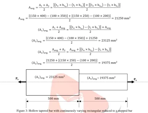
To obtain the deflection value for the tapered bar shown in Figure 2 using ANSYS it is assumed as a stepped rectangular bar of areas (A1)avg. and (A2)avg. as shown in Figure 3. The areas (A1)avg. and (A2)avg. are calculated as follows.Aavg.=A1+ A2
2 =
[(to× b1o) − (ti× b1i)] + [(to× b2o) − (ti× b2i)] 2
Aavg.=[(150 × 400) − (100 × 350)] + [(150 × 250) − (100 × 200)]
2 = 21250 mm
2
(A1)avg.=A1+ Aavg.
2 =
[(to× b1o) − (ti× b1i)] + Aavg. 2
(A1)avg.=
[(150 × 400) − (100 × 350)] + 21250
2 = 23125 mm
2
(A2)avg.=
Aavg.+ A2
2 =
Aavg.+ [(to× b2o) − (ti× b2i)] 2
(A2)avg.=
21250 + [(150 × 250) − (100 × 200)]
2 = 19375 mm
2
Figure 3: Hollow tapered bar with continuously varying rectangular reduced to a stepped bar
The theoretical deflection value for the bar shown in Figure 3 can be calculated as follows and this can be used to validate the ANSYS solution. And both of these solutions can be used to validate the new equation developed for the deflection of the tapered hollow bar of continuously varying rectangular cross section.
Total Deflection, ∆= PxL1 (A1)avg.E
+ PxL2 (A2)avg.E
Total Deflection, ∆= ( 150000 × 500 23125 × 200000) + (
150000 × 500
19375 × 200000) = 0.03557 mm
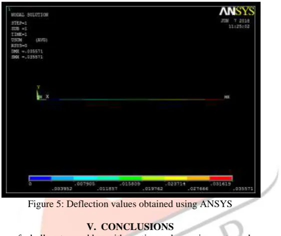
In the ANSYS finite element model is obtained by using three nodes, two nodes 1 and 3 at L = 0 and L = 1000mm respectively, another node 2 in the centre (L = 500mm) at the junction of change of area. Boundary conditions are applied to the finite element model by fixing the node 1 to all degrees of freedom as zero. And load of 150kN is applied at node 3. Figure 4 shows the applied boundary conditions to finite element model in ANSYS. Figure 5 gives the deflection values obtained using ANSYS.
Px
𝐏𝐱 𝐏𝐱 (A1)avg.= 23125 mm
2
(A2)avg.= 19375 mm2
IJEDR1802124
International Journal of Engineering Development and Research (
www.ijedr.org
)
675
Figure 4: Applied boundary conditions to a finite element modelFigure 5: Deflection values obtained using ANSYS
V. CONCLUSIONS
The equation for the deflection of a hollow tapered bar with continuously varying rectangular cross section is obtained and is given by PxL
E[to(b1o−b2o)−ti(b1i−b2i)]
log (tob1o−tib1i
tob2o−tib2i). This equation can be validated in a simple way by substituting ti = 0, b1i= 0 and b2i = 0 which gives deflection for a solid bar of continuously varying rectangular cross section as given in [1]. This simple way of validation shows that the developed is correct. The developed equation is used to get the deflection value for the assumed values of variables and the same assumed values are used to get the deflection value in ANSYS. The deflection value for the hollow tapered bar with continuously varying rectangular cross section obtained using newly developed equation is 0.03566mm and the deflection obtained from ANSYS is 0.03557mm. The percentage error in deflection values obtained from developed equation and ANSYS is 0.2495 %. Since ANSYS gives approximate solution, this error can be neglected. Hence, the developed equation of deflection for hollow tapered bar with continuously varying rectangular cross section is correct and can be directly used for the practical application involving hollow tapered bar with continuously varying rectangular cross section.
REFERENCES
[1] B. Vishwash, P. Srinivasa Pai, N. S. Sriram, R. Ahmed, H. S. Kumar, G. S. Vijay, Multiscale slope feature extraction for gear and bearing fault diagnosis using wavelet transform, Elsevier Procedia Materials Science, 5 (2014) Page No. 1650–1659, Elsevier.
[2] B. Vishwash, P. Srinivasa Pai, G. S. Vijay, S-transform and Non - negative Matrix Factorization (NMF) based Feature Extraction for Gear Condition Monitoring, International Conference on Emerging Trends in Engineering - 2014 (ICETE-2014) NMAMIT, Nitte-574110, ISBN: 978-93-83083-80-0, 15th to 17th May, 2014, Volume I and II, Page No. 142-147.
[3] B. Vishwash, P. Srinivasa Pai, G. S. Vijay, Anti-aliasing Lifting Scheme for gear fault diagnosis, Annual Research Journal (National), NMAMIT, Volume 4, October 2014, Page No. 31-35, ISSN 2249-0426.
IJEDR1802124
International Journal of Engineering Development and Research (
www.ijedr.org
)
676
[5] V. Bhat, B. Vishwash, R. Ahmed, M. R. Castelino, Artificial Neural Network based Gear fault Diagnosis usingVibration Signal: A Comparison of Feature Extraction Techniques, International Conference on Emerging Trends in Engineering - 2015 (ICETE-2015), NMAMIT, Nitte-574110, ISBN: 978-93-84935-30-6, 8th to 9th May, 2015, Volume I, Page No. 15-20.
[6] V. M. Patil, H. S. Kumar, B. Vishwash, G. S. Vijay, Comparison of Dimensionality Reduction Techniques for Effective Fault diagnosis of Rolling Element Bearing, International Conference on Emerging Trends in Engineering - 2015 (ICETE-2015), NMAMIT, Nitte-574110, ISBN: 978-93-84935-30-6, 8th to 9th May, 2015, Volume I, Page No. 21-27. [7] G. Prasad, B. Vishwash, P. Srinivasa Pai, FEA of Mechanism for Hip Manipulation, International Journal of Innovative
Research in Science, Engineering and Technology (An ISO 3297: 2007 Certified Organization), Vol. 5, Special Issue
9, May 2016, Page No. 850- 855, ISSN(Online): 2319-8753, ISSN (Print): 2347-6710,
DOI:10.15680/IJIRSET.2016.0505641, Impact factor: 6.209.
[8] N. Anand, B. Vishwash, V. S. Mahendra Kumar, Analysis of Turning and Drilling Fixture for HSU Housing Component using FEM, International Journal of Engineering Research & Technology (IJERT), Vol. 5 Issue 05, May-2016, Page No. 405-410, ISSN: 2278-0181, Impact Factor: 2.85, Crossref - DOI Prefix: 10.17577.
[9] V. Patil, B. Vishwash, Dayananda, Modification and Experimental Work on Vortex Tube, Jnanasangama- 2015, National Conference, VCET, Puttur, 2016, ISBN: 978-81-930416-1-2.
[10]Shreepannaga, B. Vishwash, Mallikappa, “Adaptive Design and Finite Element Analysis of fuselage floor beam of an
Aircraft”, International Conference on Advances in Mechanical Sciences (ICAMS 2017), Department of Mechanical Engineering, Malnad College of Engineering, Hassan, March 3rd to 5th 2017, Page No. - 47.
[11]Shreepannaga, B. Vishwash, A. Somayaji, N. Marakala, “Fatigue and Fracture Characterization of Short carbon fibres
reinforced with Al7079 metal matrix composites”, International Conference on Emerging Trends in Engineering (ICETE 2017), NMAMIT, Nitte, 12th May, 2017.
[12]B. Vishwash, “Reactions in the Body Subjected to Coplanar Non-Concurrent Forces – Validation using Ansys 10.0”,
International Journal for Research in Applied Science and Engineering Technology (IJRASET), Volume 6, Issue II, February 2018- Page No: 98 - 103, ISSN : 2321-9653.
[13]B Vishwash, Equation for Resilience in a Linearly Tapering Solid Shaft of Circular Cross Section Subjected to Torsion, International Journal of Mechanical Engineering and Technology 9(2), 2018, pp. 28–35.
[14]B Vishwash, Goutham P, "Equation for Resilience in a Linearly Tapering Hollow Shaft of Circular Cross Section Subjected to Torsion", International Journal for Research in Applied Science & Engineering Technology (IJRASET), ISSN: 2321-9653; IC Value: 45.98; SJ Impact Factor: 6.887, Volume 6 Issue III, March 2018, Page No: 2851-2858, ISSN : 2321-9653.
[15]Shreepannaga, B Vishwash, “Fracture Testing of Aluminium 7079 Metal Matrix Composites Reinforced with Nickel