Design of Induction Motor Drive using
Adaptive Fuzzy PI Controller
Y.Umamaheswari
1Dr.Rudraprathap Das
2, Dr.B.Arundhati
3,
PG Student [PID], Dept. of ECE, Vignan‟s Institute of Information Technology, Visakhapatnam, India1
Professor, Dept. of ECE, Vignan‟s Institute of Information Technology, Visakhapatnam, India2
Associate Professor, Dept. of EEE, Vignan‟s Institute of Information Technology, Visakhapatnam, India3
ABSTRACT: This paper deals with the design and comparative performance of fuzzy PI controller with conventional PI controller to control the Induction Motor speed. As the conventional control not perform well for the complex system models during the load disturbances and set point variations, Fuzzy logic has met a growing interest in many motor control applications due to its non-linearities handling features and independence of the plant modelling. This paper presents a rule-based Mamdani type fuzzy logic controller applied to closed loop Induction Motor model. The results obtained in Simulation shows that the fuzzy PI controller is performing better than the conventional PI controller.
KEYWORDS: Induction Motor, Field oriented control, Fuzzy Logic Controller, PI-Controller, Simulink.
I.INTRODUCTION
In industrial application, PI controller schemes are still the most commonly used due to their simplicity in design and stability in performance. Besides, They facing the limitations as (i) Controller design depends on the mathematical model of the system (ii) Expected performance not met due to the load changes (iii) It gives acceptable results at single set point (iv) The coefficients must be choose properly for acceptable results, besides that choosing of proper gains is very difficult for varying parameters like set point. Numerous methods such as fizzy-logic control have been proposed to replace PI controller schemes. However, unexpected change in load conditions or environmental factors would produce overshoot, oscillation of motor speed, oscillation of the torque, long settling time and thus causes deterioration of drive performance. To overcome this, an intelligent controller based on Fuzzy Logic is proposed in the place of PI regulator.
In this paper application of fuzzy logic to the intelligent speed control of indirect vector controlled induction motor drive is investigated. The analysis, design and simulation of controller have been carried out based on the fuzzy set theory.
II.FUZZY CONTROLLER
A fuzzy controller employs a mode of approximate reasoning resembling the decision making route of humans, that is, the process people use to infer conclusions from what they know. Fuzzy control has been primarily applied to the control of processes through fuzzy linguistic descriptions stipulated by membership functions.
It has certain advantages compared to classical controllers such as ease of control, low cost, and the possibility to design without knowing the exact mathematical model of plant. The Controller architecture includes some rules which describe the casual relationship between two normalized input voltages and an output one. These are Error (e), that is speed error, Change-of-error (∆e), that is derivative of speed error, and Output, defined as the change-of-control (∆T*).
III. DYANAMIC MODEL OF INDUCTION MOTOR
The dynamic modelling of Induction Motor is done in Simulink program of Matlab by utilizing its mathematical equations which are shown below. We have used synchronous frame of reference where:
𝑣𝑞𝑠𝑐= (𝑅𝑠+ 𝑝𝐿𝑠)𝑖𝑞𝑠𝑐+ 𝜔𝑐𝐿𝑠𝑖𝑑𝑠𝑐+ 𝑝𝐿𝑚𝑖𝑞𝑟𝑐+ 𝜔𝑐𝐿𝑚𝑖𝑑𝑟𝑐 (1)
𝑣𝑑𝑠𝑐 = −𝜔𝑐𝐿𝑠𝑖𝑞𝑠𝑐+ (𝑅𝑠+ 𝑝𝐿𝑠)𝑖𝑑𝑠𝑐− 𝜔𝑐𝐿𝑚𝑖𝑞𝑟𝑐+ 𝑝𝐿𝑚𝑖𝑑𝑟𝑐 (2)
𝑣𝑞𝑟𝑐= 𝑝𝐿𝑚𝑖𝑞𝑠𝑐+ (𝜔𝑐− 𝜔𝑟)𝐿𝑚𝑖𝑑𝑠𝑐+ (𝑅𝑟+ 𝑝𝐿𝑟)𝑖𝑞𝑟𝑐+ (𝜔𝑐− 𝜔𝑟)𝐿𝑟𝑖𝑑𝑟𝑐 (3)
𝑣𝑑𝑟𝑐= −𝐿𝑚 𝜔𝑐− 𝜔𝑟 𝑖𝑞𝑠𝑐+ 𝑝𝐿𝑚𝑖𝑑𝑠𝑐− 𝐿𝑟(𝜔𝑐− 𝜔𝑟)𝑖𝑞𝑟𝑐+ (𝑅𝑟+ 𝑝𝐿𝑟)𝑖𝑑𝑟𝑐 (4)
And the Mechanical equation can be written as 𝑇𝑒 = 𝐽 ∗ 𝑑𝜔𝑚 𝑑𝑡 + 𝐵𝜔𝑚+ 𝑇𝑙 (5)
𝑑𝜔𝑚 𝑑𝑡 = 1 𝐽∗ 𝑇𝑒− 𝑇𝑙 − 𝐵𝜔𝑚 =1
𝐽∗ { 3 2∗ 𝑃 2∗ 𝐿𝑚 𝑖𝑞𝑠 ∗ 𝑖𝑑𝑟 − 𝑖𝑑𝑠∗ 𝑖𝑞𝑟 − 𝑇𝑙− 𝐵𝜔𝑚 (6)
𝜔0 = base freq.; 𝜔𝑟 = rotor frame frequency
𝜔𝑠= synchronous frame frequency( Rad/sec)
Rs,Rr = Stator and Rotor resistances
Ls,Lr = Stator and Rotor inductances
Lm = Magnetizing inductance
Vqs, iqs = q axis stator voltage and current
Vds, ids = d axis stator voltage and current
Vqr, iqr = q axis rotor voltage and current
Vdr, idr = d axis rotor voltage and current
ωm = Rotor speed in mech. rad/sec
ωr = Rotor speed in electrical rad/sec
p = Number of poles Te = Electromagnetic torque
Tl = Load torque
J = Load inertia coefficient B = Friction coefficient
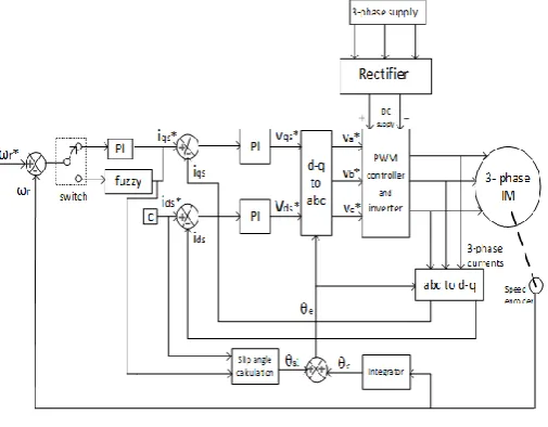
IV .PROPOSED CONTROL SCHEME
inverter output voltages through which the speed of an induction motor is controlled. Feedback signal, which is the motor speed, will be sent again to FLC. So, the closed loop control system works continuously to achieve the desired motor speed.
Fig. 2 Proposed block diagram
A. Field Oriented Control
Field oriented control (FOC) technique is intended to separate the stator currents into “flux producing (𝑖𝑑𝑠)” and “torque producing (𝑖𝑞𝑠)” components by utilizing transformation to the d-q coordinate system. These current
components can be treated separately, and then recombined to create the actual motor phase currents. This gives a solution to the better control of the motor torque, which allows higher dynamic performance. For the high performance drives, the indirect Field oriented control is preferred choice. It is essentially same as the Direct Field oriented control, except that the rotor angle 𝜃𝑒 is generated in an indirect manner (estimation) using the measured speed 𝜔𝑟 and the slip
speed 𝜔𝑠𝑙. To implement the indirect Field oriented control strategy, it is necessary to take the following dynamic
equations into consideration.
𝜃𝑒 = 𝜔𝑒𝑑𝑡 = 𝜔𝑟+ 𝜔𝑠𝑙 𝑑𝑡 = 𝜃𝑟+ 𝜃𝑠𝑙 (7)
For decoupling control, the stator flux component 𝑖𝑑𝑠 should be aligned on the 𝑑𝑒 axis, and the torque
component 𝑖𝑞𝑠 should be on 𝑞𝑒axis, that leads to 𝜓𝑞𝑟 = 0and𝜓𝑑𝑟 = 𝜓𝑟 then:
𝐿𝑟
𝑅𝑟 𝑑𝜓𝑟
𝑑𝑡 + 𝜓𝑟= 𝐿𝑚𝑖𝑑𝑠 (8)
As well, the slip frequency can be calculated as: 𝜔𝑠𝑙 =
𝐿𝑚
𝜓𝑟
𝑅𝑟
𝐿𝑟𝑖𝑞𝑠 (9)
It is found that the ideal decoupling can be achieved if the above slip angular speed command is used for making field orientation.
The constant rotor flux 𝜓𝑟 and 𝑑𝜓𝑟
𝑑𝑡 = 0can be substituted in equation (8), so that the rotor flux sets as
𝜓𝑟 = 𝐿𝑚𝑖𝑑𝑠
B. Design and Description of Fuzzy Controller
Fuzzy based controller has four major blocks one that computes the error into two input variables, a Fuzzification block, an inference mechanism, and the last step is Defuzzification.
1) Input/ Output variables
The design of the fuzzy logic controller requires predefined input and output variables. The variables entering the fuzzy logic speed controller has been selected as the speed error and its time variation. Two input variables e (k ) and ∆e(k ) , are calculated at every sampling instant as:
e(k) = 𝜔𝑟∗(k)- 𝜔𝑟(k)
∆e(k ) = e(k )- e(k-1)
Where 𝜔𝑟∗(k)is the reference speed, 𝜔𝑟(k) is the actual rotor speed and e(k-1) is the value of error at previous
sampling time.
The output variable of the fuzzy logic speed controller is the variation of command torque, ∆T*(k) which is integrated to get the reference command torque, T*(k)as shown in the following equation.
T*(k)= T*(k-1)+ ∆T*(k)
2) Fuzzification
In this stage, the crisp variables e(k ) and ∆e(k ) are converted in to fuzzy variables e and ∆e
respectively. The membership functions associated with the control variables have been chosen with triangular and trapezoidal shapes as shown in Fig. 3.
The universe of discourse of all the input and output variables are established as (-1, 1). The suitable scaling factors are chosen to brought the input and output variables to this universe of discourse. Each universe of discourse is divided into seven overlapping fuzzy sets:
Negative Large (NL), Positive Large (PL), Negative Medium (NM), Positive Medium (PM), Negative Small (NS), Positive Small (PS), Zero (ZE).
Each fuzzy variable is a member of the subsets with a degree of membership μ varying between 0 (non-member) and 1 (full-(non-member).
(c)
Fig. 3 Membership functions for (a) speed error (b) change in speed error (c) Change in torque
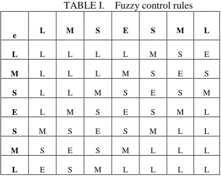
3) Knowledge base and Inference Stage
It is the process that relates input fuzzy sets to output fuzzy sets using if-then statements to make the reasonable rules. In this stage, the variables e and ∆e are processed by an inference engine that executes 49 rules as shown in Table I.
TABLE I. Fuzzy control rules C c e N L N M N S Z E P S P M P L N L N L N L N L N L N M N S Z E N M N L N L N L N M N S Z E P S N S N L N L N M N S Z E P S P M Z E N L N M N S Z E P S P M P L P S N M N S Z E P S P M P L P L P M N S Z E P S P M P L P L P L P L Z E P S P M P L P L P L P L 4) Defuzzification
In this stage a crisp value of the output variable T* is obtained by using Center Of Area (COA) is used as a deffuzification method, which can be presented as
∆𝑇∗ 𝑘 = 𝜇 ∆𝑇 ∗ 𝑖 ∆𝑇∗ 𝑖 𝑛 𝑖=1 𝜇 ∆𝑇∗ 𝑖 𝑛 𝑖=1
V. SIMULATION RESULTS AND DISCUSSION
At various set points simulation tests were carried out on induction motor drive using both conventional PI controller and fuzzy PI controller. The dynamic performance like settling time, raise time and peak overshoots for the proposed controller with conventional controller has compared.
Fig. 4 Simulation result of I.M speed for ref. speed of 300(rad/sec) at no-load
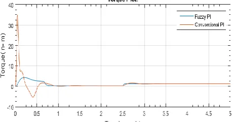
Fig. 5 Simulation result of I.M torque for ref. speed of 300(rad/sec) at no-load
In tth fig 6,7 we have set a speed of 300 rad/s to be fed so as to find out the performance with fuzzy PI controller and conventional PI controller with change in load 1N-m at 2.5 sec
In tth fig 8,9 we have set a speed of 300 rad/s to be fed so as to find out the performance with fuzzy PI controller and conventional PI controller with change in load 1N-m at 2.5 sec
Fig. 8 Simulation result of I.M speed for ref. speed of 200(rad/sec) with change in load 1N-m at 2.5 sec.
Fig. 9 Simulation result of I.M torque for ref. speed of 200(rad/sec) with change in load 1N-m at 2.5 sec.
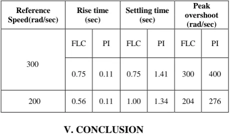
TABLE II. Comparison of FLC and PI performance in multistep speed response
V. CONCLUSION
The performance of fuzzy logic based intelligent controller for the speed control of indirect vector controlled Induction motor drive has been verified and results were compared with that of conventional PI controller performance. The simulation results obtained have confirmed the very good dynamic performance and robustness of the fuzzy logic controller during the transient and steady state period. It is concluded that the proposed intelligent controller has shown superior performance than that of the parameter fixed PI controller.
Reference Speed(rad/sec)
Rise time (sec)
Settling time (sec)
Peak overshoot
(rad/sec)
300
FLC PI FLC PI FLC PI
0.75 0.11 0.75 1.41 300 400
APPENDIX
3-Phase Induction Motor Parameters Rotor type: Squirrel cage,
Reference frame: Rotor
2.2KW, 50Hz, 4 Poles, Rs = 2.4Ω, Rr = 1.452Ω , Ls,Lr =0.121H,
Lm=0.1H, J = 0.013Kg-𝑚2, B=0.002.
REFERENCES
[1] Ichiro Miki, Naoshi Nagai, Sakae Nishiyama, Tetsuo Yamada “Vector Control of Induction Motor with Fuzzy PI Controller” Meiji University, 1991, IEEE, pp.341-346.
[2] Timothy J. Ross, Fuzzy Logic with Engineering Applications, Third Edition, Wiley student Edition, 2012.
[3] P.Tripura, Y.Srinivasa Kishore Babu, Fuzzy Logic Speed Control of Three Phase Induction Motor Drive, World Academy of Science, Engineering and Technology Vol:5 2011-12-20,pp.861-865.
[4] Blaschke F, "The Principle of Field-Orientation as applied to the New Transvector Closed-Loop Control System for Rotating-Field Machines," Siemens Review, Vol. 34, pp. 217-220, May 1972.
[5] M. Nasir Uddin, TawfikS. Radwan andM. Azizut Rahman, “Performances of Fuzzy-Logic-Based Indirect Vector Control for Induction Motor Drive,” IEEEInd. Application, Vo1.38, No. 5, pp. 1219- 1225,2002.
[6] M. A. Mannan, T. Murata, J. Tamura and T. Tsuchiya, “Indirect Field-oriented Control for High Performance Induction Motor Drives Using Space Vector Modulation with Consideration of Core LOSS,‟‟in Proceedings of PESC„03, Acapulco, Mexico, pp. 1449-1454,15-19 June, 2003.
[7] Mobammad Abdul Mannan, Toshiaki Murata, Junji Tamura and Takeshi Tsuchiya, “Fuzzy-Logic-Based Self-Tuning PI Controller for Speed Control of Indirect Field-Oriented Induction Motor Drive” SICE Annual Conference in Sapporo, August 4-6, 2004, pp.466-470.
[8] Marwan A. Badran, Mostafa A. Hamood, Waleed F. Faris, “Fuzzy Logic Based Speed Control System for Three-Phase Induction Motor” ANUL XX, NR. 1, 2013, .