A. Tahir
1, and J. Yasin
2Abstract
—
The balancing of an Inverted Pendulum by moving a cart in horizontal direction is an orthodox hitch in the region of control theory and engineering. This paper inspects the nonlinear model designing, system analysis, and control implementation of Inverted Pendulum. In order to regulate the whole set-up (i.e., both cart and pendulum), three different control tactics are experimented. These blueprints are designed in such a way that their recitals describe the settled consequences at . Performances about regulation and control energy specifications of proposed techniques are also examined.Index Term— Single Input Multiple Output, Proportional Integral Derivative, Proportional Derivative, Sliding Mode Control.
I. INTRODUCTION
Stabilization of an Inverted Pendulum is one of the most fundamental problems in control engineering [1]. For this type of regulatory problem, many researchers have developed various control methodologies [2]. However, it is still an active region of research due to its broad applications in rocket technology, missile guidance, seismometers, and in avionics systems (e.g. air planes, ships, mobile robots, and automobiles) [3][4]. Therefore, it is proven to be a best benchmark for testing a wide range of classical as well as modern control technologies.
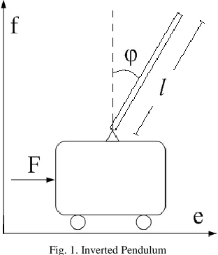
An Inverted Pendulum is a simple pendulum that is held at upright vertical position. It consists of a cart and a simple rod (with or without bob). These basic components are coupled to each other on a single board. The cart is responsible for mechanical back and forth movement in horizontal direction only [5]. Whereas, the bob hinged on a cart, is capable of rotating around its pivot point [5]. The aim of this work is to design non linear Inverted Pendulum model, analysis of the system performance, and the implementation of different control schemes. This paper focuses on: (1) the balancing of the pendulum at its erected point, and (2) the stabilization of the cart at its preferred location. Performances as well as control energy requirements for the projected control proposals are also examined.
A. Tahir
J. Yasin
Modeling, analysis, and nonlinear control design of an Inverted Pendulum plant are discussed by Torres-Pomales et. al. [6]. Implemented control designs are based on stabilization of pendulum’s position and arm tracking. For the purposes of regulation and tracking within the region of attraction, a sliding mode control (SMC) technique and variable gain Proportional Integral Derivative (PID) controllers are of interest. Results illustrate that the positions of pendulum and arm are stable after 3, and 5 seconds respectively.
Authors in [7] describe the swing up control of Inverted Pendulum with the help of energy control technique. Three Lyapunov’s functions are introduced and thus for each function, controllers are designed. By switching the control among these three controllers, swing up control mechanism of the pendulum is achieved. Simulation consequences depict that the pendulum’s angle switches its position continuously from 0 to 6.28 radians at 3 seconds to onwards.
In order to balance the linear Inverted Pendulum’s angle, the Proportional Sliding Mode Control (PSMC) design is projected by Banrejee et. al. [5]. Performance comparisons are done with Fuzzy and Proportional Integral Derivative (PID) control mechanisms. However, the settling time of pendulum’s angle using PID, Fuzzy, SMC, and proposed PSMC are after 10, 5, 15 and 5 seconds respectively.
The Proportional Integral Derivative (PID) and Proportional Derivative (PD) controllers are the simplest form of feedback control designs. These are most commonly used, and widely accepted in control engineering. Whereas, the Sliding Mode Control (SMC) strategy is highly robust in nature that has many advantages over the above mentioned traditional methods. This paper is systematized in the following parts. Modeling of Inverted Pendulum is described in second section. Conventions, parameter standards, and system analysis are also presented under second sub sections. Third segment deals with the designing portion, where the Inverted Pendulum control is implemented with the use of three different ideas. End results and their analysis are worked out under fourth fragment. In five, conclusions and future effort are portrayed.
II. ARITHMETICAL MOLDING
Let an arrangement consisting of cart-pole system shown in Fig. 1.
Fig. 1. Inverted Pendulum
Using balancing equations, the nonlinear model for the Inverted Pendulum is derived as,
2sin cos
cos sin 0
m e ml ml F
me ml ma
(1)
Its equivalent state space representation is,
24
0
cos
0
1
m n
po
lq
lq
F
pr
ao
q
q
(2)
Where,
1
sin
n
a
,1 1
sin
cos
o
m
,2 2
p
l
,2 1
cos
q
m m
, And,1
sin
r
m
The output block is given as,
1
1
0
0
0
2
0
0
1
0
3
4
f
C
(3)
A. Conventions
Force that is applied to the system is considered positive on the right side. Linear displacement is negative on left half
plane. And, angular rotation of pendulum is well thought-out to be positive in the right half s-plane.
B. Parameter Standards
Following are the assigned values to the Inverted Pendulum system parameters.
TABLE I System Parameters [8] Parameters Assigned Values
∂ 2.63 Kg
m 0.162 Kg
l 0.255 m
a 9.8 m/s2
Where, ∂, m, and l symbolize the mass of the cart, mass of the bob, and pendulum rod length respectively.
C. System Analysis
Inverted Pendulum is a Single Input Multiple Output (SIMO) electromechanical system. Also, it is a non-minimum phase, under actuated, nonlinear system, and highly an open loop unstable in nature. This system has four open loop poles, which are located at:
0, 0,
2.9677, 2.9677
(4)Therefore, this type of organization behavior defines the most difficult problems in the field of engineering.
III. PROJECTED CONTROLLERS
A. Proportional Integral Derivative (PID)
Design
The PID controller is one of the basic widely acceptable schemes in industry. Classical PID technology is based on Single Input Single Output (SISO) systems. Therefore, proposed method is described in Fig. 2.
r e u Theta
X
PID Plant
+
Fig. 2. Block Diagram of Single PID Controller
Fig. 2 illustrates that the control force is,
d p i
F
H e
H e
H edt
(5)TABLE II Single PID, Inserted Values System Type of Values
Zeros Pendulum -0.625±0.696i
B. Proportional Derivative (PD) Design
In order to stabilize pendulum while reducing settling time, following block diagram is implemented.
r e u Theta
X
PD Plant
+
-
-+
Fig. 3: Block Diagram of PD Controller
d p
F
H e
H e
(6)Single PD angle and cart controller is used in Fig. 3. Following values are introduced in tuning the controller.
TABLE III Single PD, Inserted Values
System Type of Values Zeros Pendulum 0, -1.43 C. Sliding Mode Control (SMC) Design
SMC is one of the precious control techniques for the extremely nonlinear, unbalanced, and under actuated structures. This theory can be applied to both linear as well as nonlinear systems, and has been proposed for more than fifty years [3].
Consider changing time area ( ), in the state space ( ) by the scalar equation ( ) [9][10]. Therefore, following sliding surfaces are chosen as,
1 1 2 2 3 3 4 4 e
s
c
c
s
c
c
(7)And, like control laws are,
ee e e
F
sgn s
F
sgn s
(8)In equation (7), be the tracking error, and c is the control design parameter. Γ, and δ and 𝛺 are the control plan constraints described in equation (8).
( ) is the signum function, defined as,
1
0
1
0
if s
sgn s
if
(9)From the above equations, when in (7), the control equivalent has the given values as,
1 4
1 2
3
1
cos
e
c
lq
m n
po
c
q
pr
oa
(10)
For the continuation of control laws, the system has some given design restrictions,
1
π
0,
2
q
n
(11)Where,
Proposed control equations in (8) guarantee the reach-ability and sliding conditions as under,
2
1
2
d
V
s
s
dt
(12)System courses strike at the sliding surface in a limited time. This is due to the severely positive constant .
IV. CONSEQUENCES AND ANALYSIS
During the implementation, different outcomes (according to the performance criteria) are achieved from three proposed controller designing. The initial condition given to pendulum is radians in each case.
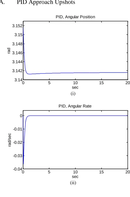
A. PID Approach Upshots
(i)
(ii)
0 5 10 15 20
3.14 3.142 3.144 3.146 3.148 3.15 3.152
sec
ra
d
PID, Angular Position
0 5 10 15 20
-0.04 -0.03 -0.02 -0.01 0
sec
ra
d
/se
c
(iii)
(iv)
(v)
B. PD Approach Upshots
(vi)
(vii)
(viii)
(ix)
(x)
C. SMC Approach Upshots
0.1 meters is set as the initial condition of cart.
0 10 20 30 40 50
0 0.02 0.04 0.06 0.08 0.1 0.12
sec
m
PID, Linear Position
0 10 20 30 40 50
0 5 10 15
20x 10
-3
sec
m
/se
c
PID, Linear Rate
0 5 10 15 20
-0.1 -0.05 0 0.05 0.1 0.15 0.2
sec
N
PID, Control Action
0 5 10 15
3.14 3.145 3.15
sec
ra
d
PD, Angular Position
0 5 10 15
-0.04 -0.03 -0.02 -0.01 0 0.01
sec
ra
d
/se
c
PD, Angular Rate
0 5 10 15
-2 0 2 4 6
8x 10
-3
sec
m
PD, Linear Position
0 5 10 15
-0.01 -0.005 0 0.005 0.01 0.015
sec
m
/se
c
PD, Linear Rate
0 5 10 15
-0.1 -0.05 0 0.05 0.1 0.15 0.2
sec
N
(xi)
(xii)
(xiii)
(xiv)
(xv)
(xvi)
(xvii)
(xviii)
The analysis of implemented results is illustrated in the following tables.
TABLE IV
Pendulum, Performance Characteristics
Response PID PD SMC
Settling Time (sec) 7 6 0.35
Steady State Error 0.0 0.0 0.0
0 0.2 0.4 0.6 0.8 1
3.14 3.142 3.144 3.146 3.148 3.15 3.152
sec
ra
d
SMC, Angular Position
0 0.2 0.4 0.6 0.8 1
-0.08 -0.06 -0.04 -0.02 0
sec
ra
d
/se
c
SMC, Angular Rate
0 1 2 3 4 5
0 0.02 0.04 0.06 0.08 0.1
sec
m
SMC, Linear Position
0 1 2 3 4 5
-0.1 -0.05 0
sec
m
/se
c
SMC, Linear Rate
0 0.2 0.4 0.6 0.8 1
-1 -0.5 0 0.5 1 1.5
sec
N
SMC, Pendulum Control Action
0 1 2 3 4 5
-2 0 2 4 6
sec
N
SMC, Cart Control Action
0 0.2 0.4 0.6 0.8 1
-0.1 -0.05 0
sec
S
(x)
SMC, Pendulum Switching Surface
0 1 2 3 4 5
0 0.2 0.4 0.6 0.8
sec
S
(x)
TABLE V
Cart, Performance Characteristics
Response PID PD SMC
Settling Time (sec) 25 8 1.2
Steady State Error 0.0 0.0 0.0
V. CONCLUSION AND FUTURE WORK
It is seen from the above end products and analysis that all the planned models work to stabilize the Inverted Pendulum. The implemented PID’s control design has the slowest response due to Integral term, while the PD’s controlling proposal improves this transient response. Furthermore, outcomes also reveal that, experimented SMC scheme depicts the best results, when compared to PID’s and PD’s. This methodology has less settling time as well as the best response, when it reaches to the unstable point. However, due to applied discontinuous control signal, fast and finite amplitude oscillations (known as chattering) are generated, which travel to the plant in a controlled manner. In addition, the future scope belongs to the cutback of produced chattering phenomenon, exclusive of upsetting the basic nature of the controller itself.
ACKNOWLEDGEMENT
The authors thank Prof. Dr. Aamer Iqbal Bhatti, and Mr. Mehmood Pervaiz for their continual support and lots of noble helps in good instance.
REFERENCES
[1] Khalil Sultan “Inverted Pendulum Analysis, Design and Implementation”, IIEE Visionaries Document Version 1.0 [2] A. K. Yadav, P. Gaur, A.P. Mittal, and M. Anzar, “Comparative
Analysis of Various Control Techniques for Inverted Pendulum,” India International Conference on Power Electronics, (January 2011), pp. 1 – 6.
[3] Zhiping Liu, Fan Yu, and Zhi Wang, “Application of Sliding Mode Control to Design of the Inverted Pendulum Control System,” 9th International Conference on Electronic Measurement & Instruments, (August 2009), pp. 3-801 – 3-805.
[4] Witchupong Wiboonjaroen, and Sarawut Sujitjorn, “Stabilization of an Inverted Pendulum System via State-PI Feedback,” International Journal of Mathematical Models and Methods in Applied Sciences, vol. 5, no. 4 (2011), pp. 763 – 772.
[5] Anirban Banrejee, and M. J. Nigam, “Designing of Proportional Sliding Mode Controller for Linear One Stage Inverted Pendulum,” Power Engineering and Electrical Engineering, vol. 9, no. 2 (June 2011), pp. 84 – 89.
[6] W. Torres-Pomales, and O. R. Gonzalez, “Nonlinear Control of Swing-Up Inverted Pendulum,” Proceedings of the IEEE International Conference on Control Applications, (September 1996), pp. 259 – 264. [7] T. Maeba, Mingcong Deng, A. Yanou, and T. Henmi, “Swing-Up
Controller Design for Inverted Pendulum by using Energy Control Method Based on Lyapunov Function,” Proceedings of the International Conference on Modeling, Identification and Control, Published in IEEE, (July 2010), pp. 768 – 773.
[8] User Manual for Inverted Pendulum, National Development Complex (NDC)-NESCOM, Islamabad-Pakistan.
[9] J-J E. Slotine, and W. Li, Applied Non Linear Control (Englewood Cliffs, N.J.: Prentice-Hall, 1991).
[10] V. Utkin, J. Guldner, and J. Shi, Sliding Mode Control in Electromechanical Systems, (London: Taylor & Francis, 1999).
BIBLIOGRAPHY
A. Tahir1 received her Bachelor’s and Master’s Degree in Computer Engineering and Electrical Engineering respectively from COMSATS Institute of Information Technology (CIIT), Islamabad-Pakistan. This author is working in International Islamic University (IIU), Islamabad-Pakistan.