(NCMTEE-2K17) 27th March 2017
SIMULATION AND CONTROL TECHNIQUE FOR SINGLE PHASE SUB
MODULE INTEGRATED PV SYSTEM
MS. JYOTI C. DESHMUKH
Dept. of Electrical Engg. Solapur University
PROF. A. A. CHANDANE
Dept. of Electrical Engg. Solapur University
PROF. S. S. RASHINKAR
Dept. of Electrical Engg. Solapur University
ABSTRACT
The photovoltaic (PV) system that is based on sub module-integrated converters (subMICs) is capable of maximizing solar energy harvest by eradicating power losses due to intrapanel mismatch. Modeling and simulation of subMIC-based systems are important to study the effect of PV partial shading, prove new control strategies, analyze distributed system dynamics, optimize system configurations, and determine system parameters, etc. However, the simulation of such systems can be very challenging due to the large number of switching-mode power units, nonlinear nature of PV generators, and complication of the coordinating control. This project provides an effective solution to simulate and control single-phase grid-tied PV systems that are based on a practical subMICs configuration by sliding mode control. The approach includes the simplified PV cell model and averaged model for power converters, which consider all dynamic interactions among the maximum power point tracking (MPPT).
INDEX TERMS: DC/DC power conversion, energy harvesting, photo voltaic power system, simulation.
I. INTRODUCTION
Photovoltaic (PV) array is usually composed of solar panels, which are connected in series-parallel combination to meet high input voltage requirement of the centralized power inverter for grid connection. However, significant power loss has been reported due to the unbalanced generation among PV panels, which is primarily caused by partial shading[1]-[4].The dc/dc power optimizer (DCPO), which incorporates a dedicated converter for every panel, has been proposed by researchers to minimize energy loss during mismatch conditions. Each DCPO performs independent maximum power point tracking (MPPT) to mitigate the mismatch effect among the series-connected solar panels. This configuration successfully eliminates the power loss
resulting from the inter panel mismatch but cannot mitigate the loss caused by inter panel mismatch. To increase solar energy harvest by era dicatingintra panel mismatch, sub module integrated converters (sub MICs) have been developed. Both DCPO and sub MIC are similarly designed for cascaded structures where converter outputs are connected in series. Modeling and simulation of sub MIC-based systems are necessary to analyze the impact of partial shading, prove new control strategies, Optimize system configurations, and analyze system dynamics, etc. Furthermore, the evaluation of the system performance under uniform shading, partial shading, and non shading conditions can also be carried out using different modeling approaches.
(NCMTEE-2K17) 27th March 2017
the power output are considered, which include double frequency ripple, temperature variations, uniform irradiance changes, uneven PV temperature distribution, and partial shading scenarios. Additionally, the model accounts for the effect of changes in grid voltage and
frequency and shows their influence on the dc-link and inverter input current. Furthermore, the discrete dc-link voltage control and PV submodule voltage regulation is applied, which emulates the actual digital control using microcontrollers in a real-world system.
Fig.1 Diagram of subMIC-based PV system for single-phase grid connection
The proposed modeling and simulation is used to compare the performance of subMICs with a standard grid-tied system based on a centralized PV inverter under the real-world solar irradiance and various PV mismatch conditions, e.g., partial shading and uneven temperature distribution.
II. MODELLING OF PV CELL
Among a variety of renewable energy sources, solar energy is predicted to become the largest contributors to world energy for its clean and no supply limitations characteristic. Over the past decade, PV technology has shown the potential by robust and continuous growth even during times of financial crisis.
The key technology of a PV system includes PV cell modeling, maximum power point tracking (MPPT) algorithm, DC/DC converter and grid-connected DC/AC inverter.Photovoltaic (PV) cell is a semiconductor device that absorbs and converts the energy of light into electricity by photovoltaic effect.Figure shows the equivalent circuit of PV Cell. By applying Kirchhoff law, current will be obtained by the equation:
IP, is the current leak in parallel resistor.
Equivalent circuit of PV Cell
According to the equation, the output current of a module containing Ns cells in series will be:
A. DETERMINATION OF THE PARAMETERS:
The number of parameters varies depending on the chosen model and on the assumptions adopted by the searchers.It is considered that Iph, Is,Rs, Rp and the factor ideality are fiveparameters that depend on the incident solar radiation and the cell temperature.
In this work the four parameters that have to be evaluatedare also Iph, Is, RS,RP.
DETERMINATION OF IP:
𝐈𝐩𝐡= 𝐓𝐨𝐩− 𝐓𝐫𝐞𝐟 . 𝐊 + 𝐈𝐬𝐜 . 𝐈𝐫𝐫
(NCMTEE-2K17) 27th March 2017
current, Tref=Cell temp at STC=25+273=298K, Top=Operating temp.
DETERMINATION OF IS:
𝐈𝐬= 𝐈𝐫𝐬. 𝐓𝐨𝐩 𝐓𝐫𝐞𝐟 𝟑 . 𝐞 𝟏 𝐓𝐨𝐩− 𝟏 𝐓𝐫𝐞𝐟 𝐪.𝐄𝐠 𝐊.𝐧
Where, Irs=Reverse saturation current at operating temperature, q=Charge, Eg=Material band gap energy=1.12eV for Si.
Fig. Presentation of PV Model
III. SUBMODULE INTEGRATED CONVERTERS
Under the small-scale mismatch conditions, the sub MIC based PV system is superior to the systems of DCPO and centralized configuration in terms of solar energy harvesting. It is shown that the sub MICs offer an effective solution to maximize the utilization of PV power by employing MPPT on the sub module level. The sub module is a section of a PV panel consisting of 15 to 24 PV cells in series connection.
Advantage of sub MICs systems lies in the utilization of distributed MPPT to the sub module level to eradicate mismatch among sub modules. Therefore, the sub MICs-based system shows higher energy yield in comparison with the centralized inverter, DCPO, and micro inverter configurations. In a quantitative comparison of PV energy harvesting architectures of string, power optimizer, micro inverter, and sub MICs is presented. The 30-year prediction of solar energy harvest showed that the sub MIC-based system produces more energy than other system approaches with the consideration of various types of installations including ground-mounted power plant, rooftop installation, facade PV, and electric vehicles. 90% of the mismatch loss can be recovered by applying a unified control approach, which controls three sub-MICs connected to each PV panel. In [9], a subMIC product is developed, which reports 20% more energy harvesting in comparison with the DCPO under specific shading conditions. The study in [10] compares the performance
of the sub MIC solution with centralized PV system and reports 6.9%–11.1% more annual energy output. Furthermore, the sub MIC-based system have been proved to be low cost and high efficiency [9].
In sub MIC architecture, the inputs of dc/dc converters are connected in parallel to sub modules to perform MPPT, whereas the outputs are connected in series. The series connection of sub MICs delivers a voltage stack to achieve the required dc-link voltage, which is the input of a centralized grid-tied inverter. The voltage stack provides the flexibility to operate each sub-MIC at relatively low conversion ratio, which results in higher efficiencies compared to the solution of micro inverters. A typical micro inverter is required to boost the voltage from the PV module level of 22–45 Vdc to the grid level of 220 Vrmsor 240 Vrms in ac [8]
IV. MAXIMUM POWER POINT ALGORITHM
To improve the efficiency of the solar panel MPPT is used. According to maximum power point theorem, output power of any circuit can be maximize by adjusting source impedance equal to the load impedance, so the MPPT algorithm is equivalent to the problem of impedance matching. In present work, the Boost Converter is used as impedance matching device between input and output by changing the duty cycle of the converter circuit. Output voltage of the converter is depend on the duty cycle, so MPPT is used to calculate the duty cycle for obtain the maximum output voltage because if output voltage increases than power also increases. In this Perturb and Observe (P&O) and constant duty cycle techniques are used, because these require less hardware complexity and low-cost implementations
A. PERTURB & OBSERVE MPPT ALGORITHM :
A photovoltaic (PV) array under uniform irradiance exhibits a current-voltage characteristic with a unique point, called the maximum power point (MPP), where the array produces maximum output power.
(NCMTEE-2K17) 27th March 2017
Flow chart of P&O MPPT
It is the simplest method of MPPT to implement. In this method only voltage issensed, so it is easy to implement. In this method power output of system is checked by varying the supplied voltage. If on increasing the voltage, power is also increases then further ‘δ’ is increased otherwise start decreasing the ‘δ'. Similarly, while decreasing voltage if power increases the duty cycle is decreased. These steps continuetill maximum power point is reached. The corresponding voltage at which MPP is reached is known as reference point (Vref).
V.DC/DC CONVERTER
A DC/DC converter serves the purpose of transferring maximum power from the solar PV cell to the load. A DC/DC converter acts as an interface between the load and the PV cell. By changing the duty cycle, the load impedance is varied and matched at the point of the peak power with the source, so as to transfer the maximum power.
There are Four basic topologies for DC/DC converter: Buck, Boost, Buck-Boost and Cuk.
A. REASON FOR CHOOSING BOOST CONVERTER:
Chosen the classical boost converter to implement the MPPT algorithm for the following reasons.
1) For Boost Converter, the output voltage is always higher than the input PV cell voltage, which is convenient for the PV cell to be connected to the grid later.
2) The topology for Boost Converter is simple, easy to implement, and has high efficiency.
3) The Boost Converter is easy to be controlled to minimize fluctuation and increase tracing accuracy.
B. OPERATING PRINCIPLE OF BOOST CONVERTER:
Below Fig shows the topology of Boost converter. For this converter, power flow is controlled by means of the on/off duty cycle of the switching transistor. When the
switch is On forton seconds, current flows through the inductor in clockwise, and energy Vi.Il.ton is stored in the inductor. When the switch is Off for toffseconds, current will be reduced for increasing impedance. The only path of the inductor current is through diode D to the capacitor C and load R. The polarity of inductor will change. And the energy accumulated in the inductor during the On-State will be released, (Vc-Vi)Il.toff.
Vi.Il.ton=(Vc-Vi)Il.toff
Topology of Boost Converter
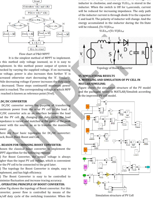
VI. SIMULATION& RESULTS
A. MODELING AND SIMULATION OF PV CELL IN MATLAB/SIMULINK:
Figure shows the simulation structure of the PV model and the packaged model in MATLAB/Simulink according to the improved PV cell model.
(NCMTEE-2K17) 27th March 2017
Fig.1 I-V Characteristic Curve of PV Cell
The simulation result is shown in Figures. Figure 1 shows the I-V characteristic curves of the PV cell. Figure 2 shows the P-V characteristic curves. The model curves exactly match with the experimental data at three remarkable points: short-circuit, open-circuit, and maximum power point. It can be seen that when the output voltage is less than a threshold value, the change of output current is very small with the changing of voltage. PV cell acts like a constant current source; when the output voltage exceeds a threshold value, the current declines sharply with increasing voltage. PV cell acts like a constant voltage source.
Fig.2 P-V Characteristic Curve of PV Cell
The I(V) characteristics are presented in by varying irradiance from 200 W/m2 to 1000 W/m2 and taking The STC temperature.
Fig.3 I-V characteristic of varrying irradiance
B. SIMULATION MODEL FOR P&O MPPT ALGORITHM:
C. SIMULATION MODEL FOR DC/DC CONVERTER:
(NCMTEE-2K17) 27th March 2017
Waveform of V/I/P
VII. CONCLUSION
In this project, an efficient and fast simulation technique is presented to simulate sub MIC-based grid-tied PV systems, which is a difficult problem due to the significant number of PV sub modules and sub MICs. A comprehensive control strategy is also developed to coordinate the control of Distributed Maximum Power Point Tracking, PV sub module voltage regulation, dc-link voltage regulation, and grid-tied current injection. The simulation model is developed using the averaging technique of power converters in combination with the simplified PV model, which illustrates the dynamic interaction among DMPPT, PVVR, and DCLVR during various partial shading conditions.
VIII. REFERENCES
1) G. R. Walker and P. C. Sernia, “Cascaded DC–DC converter connection of photovoltaic modules,” IEEE Trans. Power Electron., vol. 19, no. 4, pp. 1130–1139, Jul. 2004.
2) E. Roman, R. Alonso, P. Ibanez, S. Elorduizapatarietxe, and D. Goitia, “Intelligent PV module for grid-connected PV systems,” IEEE Trans. Ind.Electron., vol. 53, no. 4, pp. 1066–1073, Jun. 2006.
3) H. Zheng, S. Li, and J. Proano, “PV energy extraction characteristic Study under shading conditions for different converter configurations,” in Proc.IEEE Power Energy Soc. Gen. Meeting, 2012, pp. 1–8. 4) A. Maki and S. Valkealahti, “Power losses in long
string and Parallel connected short strings of series-connected silicon-based Photovoltaic modules due to partial shading conditions,” IEEE Trans. Energy Convers.,vol. 27, no. 1, pp. 173–183, Mar. 2012.
5) N. Femia, G. Lisi, G. Petrone, G. Spagnuolo, and M. Vitelli, “Distributed maximum power point tracking of photovoltaic arrays: Novel approach and system analysis,” IEEE Trans. Ind. Electron., vol. 55, no. 7, pp. 2610–2621, Jul. 2008.
6) W. Xiao, N. Ozog, and W. G. Dunford, “Topology study of Photovoltaic interface for maximum power point tracking,” IEEE Trans. Ind. Electron.,vol. 54, no. 3, pp. 1696–1704, Jun. 2007.
7) W. Saranrom and S. Polmai, “The efficiency improvement of series connected PV panels operating under partial shading condition by using per-panel DC/DC converter,” in Proc. Int. Conf. Elect. Eng. Electron. Comput. Telecommun. Inf. Technol. (ECTI-CON), 2011, pp. 760–763.
8) F. Wang, X. Wu, F. C. Lee, and F. Zhuo, “Analysis of unified output MPPT control in sub-panel PV converter system,” in IEEE Trans. Power Electron., vol. 29, no. 3, pp. 1275–1284, Mar. 2014.
9) R. C. N. Pilawa- Podgurski and D. J. Perreault, “Sub module integrated distributed maximum power point tracking for solar photovoltaic applications,” IEEE Trans. Power Electron., vol. 28, no. 6, pp. 2957 2967, Jun. 2013.