Design and Implementation of Camera-Based
Interactive Touch Screen
Dr. Siny Paul Vishnu P
Associate Professor UG Student
Department of Electrical and Electronics Engineering Department of Electrical and Electronics Engineering Mar Athanasius College of Engineering, Kothamangalam Mar Athanasius College of Engineering, Kothamangalam
Susmitha James Sona Jo Madhavathu
UG Student UG Student
Department of Electrical and Electronics Engineering Department of Electrical and Electronics Engineering Mar Athanasius College of Engineering, Kothamangalam Mar Athanasius College of Engineering, Kothamangalam
Abstract
Camera-based Interactive Touch Screen is a touch detection technique that uses a camera to provide a large display with very high spatial and temporal resolutions. The conventional touch screen technology and presentation methods face a range of restrictions. However, the camera-based touch detection can overcome all these restrictions and turn projection screens into interactive touch displays, creating a through-window experience. It uses a coated sheet of glass as the projection surface to form a two-dimensional display. The camera captures images of the projection surface continuously, which are processed by the Atmega16 microcontroller. A UART module connected to the microcontroller, provides asynchronous serial communication with external devices, synchronisation of the serial data stream and recovery of data characters. This technology has several advantages over other touch detection technologies, such as its low cost, simple design and scalable structure. The applications of this technology include advertising, presentations and outdoor displays.
Keywords: Camera, Coated Glass, Presentation, Projector, Touch Screen, UART Module
_______________________________________________________________________________________________________
I. INTRODUCTION
Since the early 1970s, touch screen technologies have become common in many everyday applications. Ranging from ATM machines, to PDAs, to the first commercially available tablet PC developed by IBM in 1993, touch screen technologies find a wide range of uses in our lives. Despite the rapid improvements in this field, it is still difficult to construct an inexpensive touch screen sensor that can register multiple simultaneous points of contact.
Past attempts to create touch screens have focused on the use of individual sensors. A touchscreen is an input device normally layered on the top of an electronic visual display of an information processing system. A user can give input or control the information processing system through simple or multi-touch gestures by touching the screen with a special stylus and/or one or more fingers. Some touchscreens use ordinary or specially coated gloves to work while others use a special stylus/pen only. The user can use the touchscreen to react to what is displayed and to control how it is displayed; for example, zooming to increase the text size.
Touchscreens are common in devices such as game consoles, personal computers, tablet computers, electronic voting machines and smartphones. They can also be attached to computers or, as terminals, to networks. They also play a prominent role in the design of digital appliances such as personal digital assistants (PDAs) and some books (E-books).
The touchscreen enables the user to interact directly with what is displayed, rather than using a mouse, touchpad, or any other intermediate device (other than a stylus, which is optional for most modern touchscreens). The development of multipoint touchscreens facilitated the tracking of more than one finger on the screen; thus, operations that require more than one finger are possible. These devices also allow multiple users to interact with the touchscreen simultaneously.
The information flows in two ways: there are commands from the computer that changes the different characteristics of the camera, and images from the camera that are sent to the computer. The communication between the computer and the AVR is implemented through the serial port and the communication between the camera and the microcontroller is done using the I2C protocol that can access the different registers of the camera. An 8 bit port is used to read the images.
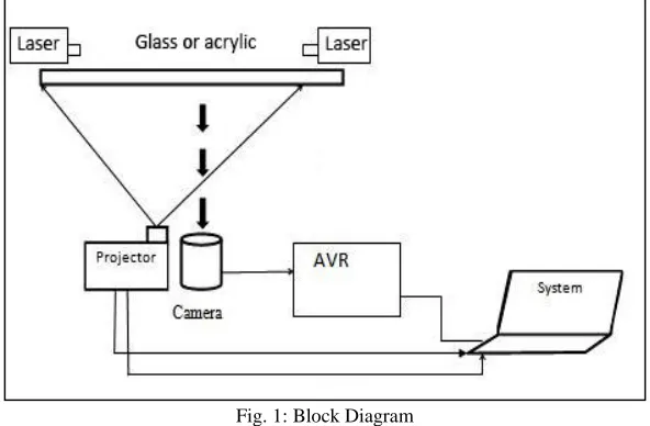
Fig. 1: Block Diagram
The surface is illuminated by single or multiple lasers. The laser plane of light is about 1mm thick and proximally positioned to the touch surface. The laser module has a built-in driver. The display is projected on to the coated glass screen by the projector placed behind the screen. The camera behind the screen continuously captures the images. The camera transmits the images as RGB data to the microcontroller. The microcontroller communicates with the system through a UART module [1]-[4].
Camera-Microcontroller Interface
The camera-microcontroller interfacing forms the main part of the project. A C3088 color camera module with digital output is used. It uses a CMOS image sensor OV6620 from Omnivision. It has a digital video port that supplies a continuous 8/16 bit-wide image data stream. All the camera functions, such as exposure, gamma, gain, white balance, windowing, can be changed through I2C interface by writing in some registers.
The video output can be expressed in different formats, and with different type of channels (RGB, UVY). The information is sent continuously and is synchronized by the HREF, VSYNC and PCLK signals as shown in Figure.
The VSYNC signal indicates new frame, the HREF signal indicates if the information is valid and makes the horizontal synchronization, and PCLK is the clock signal (the data is valid in the rising edge). The period of PCLK can be changed by writing in the registers of the camera. This will allow to read images from the camera directly with the microcontroller without the use of additional hardware. The registers accessed by the I2C bus allow to change different properties of the camera. In this project, they are used to change the period of PCLK, to read the size of the image, to make a mirror of the image, and to reset the camera.
As the initial frequency of PCLK is 17.73 MHz and the AVR is not fast enough to read each pixel at this frequency, there are two possible solutions:
Use additional hardware to read and store the image.
Decrease the frequency of PCLK by writing in the register 0x11.
Fig. 2: AVR-camera interfacing
The horizontal reading is used to read one horizontal line and make a little image process of it. The selection of this frequency was made experimentally trying to use the highest as possible frequency. When an image is to be sent to the computer, the headers and the palette are sent to the computer and then we proceed to reading the image from the camera. We read each frame and column and send the data pixel by pixel through the serial port to the computer [5].
I2C Protocol
Inter-Integrated Circuit, abbreviated as I2C, is a serial bus short distance protocol developed by Philips Semiconductor about two decades ago, to enhance communication between the core on the board and various other ICs involved around the core.
The most popular serial bus communication protocols available today in the market are, SPI, UART, I2C, CAN, USB, IEE1394, and so on. Philips originally developed I2C for communication between devices inside a TV set. Examples of simple I2C-compatible devices found in embedded systems include EEPROMs, thermal sensors, and real-time clocks. I2C is also used as a control interface for signal processing devices that have separate, application-specific data interfaces. Philips, National Semiconductor, Xicor, Siemens, and other manufacturers offer hundreds of I2C-compatible devices. I2C buses can typically reach speeds up to 400 Kbps.
I2C is appropriate for interfacing devices on a single board, and can be stretched across multiple boards inside a closed system. An example is a host CPU on a main embedded board using I2C to communicate with user interface devices located on a separate front panel board. I2C is a two-wire serial bus. The chip select or arbitration logic is not required, making it cheap and simple to implement hardware. The two important I2C signals are serial data and serial clock. Together, these signals make it possible to support serial transmission of 8-bit data. i.e. 7-bit device addresses plus control bits-over the two-wire serial bus.
An I2C slave can hold off the master in the middle of a transaction using what's called clock stretching (the slave keeps SCL pulled low until it's ready to continue). Most The I2C protocol can also support multiple masters. There may be one or more slaves on the bus. Both masters and slaves can receive and transmit data bytes.
Operation
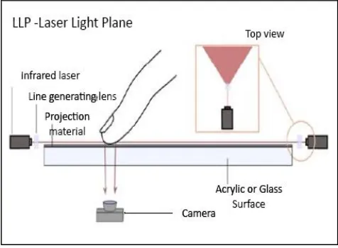
Laser light plane (LLP) technique used here is one of the newest illumination and tracking methods for surface touches. As opposed to the other optical sensing techniques that employ several arrays of LEDs to generate radiation, the LLP method uses commonly available laser diodes paired with line generating lenses. By placing several lasers in the corners of the multitouch device, a light plane is generated that will cover the whole active surface area. Depending on the size of the device, 2 to 8 lasers are commonly employed. Generally, two lasers placed infront of the screen would generate enough radiation to extend the light plane to the required dimensions. Since the light plane can be blocked by placing a finger or an object there is a need for an illumination redundancy where even the hidden markers receive sufficient lighting in order to scatter the radiation towards the sensing element.
The laser plane is 1 mm in thickness and is positioned infront of the surface at a distance varying from 0.5 to 2 mm. When an object comes in contact with the laser plane, radiation is scattered towards the camera that acts as the radiation detector. The common laser wavelength used in this method is 635 nm for the increased availability of optical filters and greater environment immunity.
The display is projected on to a coated glass screen by the projector placed behind the screen. The camera behind the screen continuously captures the images. .When a finger touches the light plane, it gets lighted up by an arrangement of plane red laser light modules infront of the screen. Thus, the point of touch is viewed by the camera as an intense red spot. The camera transmits the images as RGB data to the microcontroller which calculates the x and y coordinates of the point with highest intensity of red. The data is then sent to the system through a UART module to produce the required response. Thus touch is generated on the glass surface [7-11].
Fig. 3: Laser Light Plane Technique
III. HARDWARE DESCRIPTION
The various hardware components used in the project are:
Coated Glass
The sheet of glass used as the touch screen is coated with a layer of acrylic, so as to form an image on the screen. Acrylic is a useful, clear plastic that resembles glass. Common brands of acrylic include polycast, lucite, plexiglass or optix. It is available in a variety of thicknesses, colours and niche. The most popular uses for acrylic signage include facility signs and interior dimensional lettering. It can be printed, routered, engraved, beveled, polished, painted, cut, glued, bent, drilled and lasered. Acrylic does not blast well[12].
Camera C3088
The C3088 is a 1/4” colour camera module with digital output. It uses OmniVision’s CMOS image sensor OV6620. Combining CMOS technology together with an easy to use digital interface makes C3088 a low cost solution for higher quality video image application. The digital video port supplies a continuous 8/16 bit -wide image data stream. All camera functions, such as exposure, gamma, gain, white balance, color matrix, windowing, are programmable through I2C interface.
Atmega16 microcontroller
Plane Laser Light Module
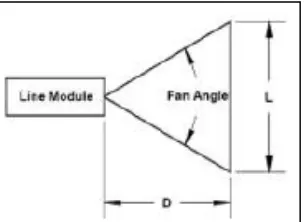
These are encapsulated laser diodes of Class IIIa 5mW, with a 650nm red wavelength. They can be driven from 2.8V to 5.2V. This particular laser diode has a lens attached to turn the dot into a line. The line beam spread is 120°. The line fades out and doesn't have a sharp cut-off.
It is not a laser pointer, but a diode with an integrated driver and requires a 3 V to 5 V DC power supply. It has a 5mW output, and a safety label marked on it.
UART Module
A UART (Universal Asynchronous Receiver/Transmitter) is the microchip with programming that controls a computer's interface to its attached serial devices. Specifically, it provides the computer with the RS-232C Data Terminal Equipment (DTE) interface so that it can "talk" to and exchange data with modems and other serial devices.
IC Voltage Regulator
Voltage regulator ICs are available with fixed (typically 5, 12 and 15V) or variable output voltages. They are also rated by the maximum current they can pass. Negative voltage regulators are available, mainly for use in dual supplies. Most regulators include some automatic protection from excessive current ('overload protection') and overheating ('thermal protection'). Many of the fixed voltage regulator ICs has 3 leads and look like power transistors, such as the 7805 +5V 1Amp regulator. They include a hole for attaching a heat sink.
Projector
A projector or image projector is an optical device that projects an image (or moving images) onto a surface, commonly a projection screen. Most projectors create an image by shining a light through a small transparent lens, but some newer types of projectors can project the image directly, by using lasers.
Projector is a highly versatile tool for presentation. Here we use a projector (BENQ/EPSON) to project the computer screen to the plane glass with the help of thin acrylic sheet.
PC/Laptop
We do not need to build a computer specifically for this project. In fact, any recent computer with a decent processor and graphics card should work well. However, if you plan on putting the surface in an enclosure when you are done, then ensure t he computer has adequate cooling and minimal thermal dissipation.
IV. EXPERIMENTAL SETUP AND RESULT
Various parts of the system are constructed and connected together to work in unison. The mechanical parts do not interact with the electrical parts, which simplifies the design. The main requirement of the mechanical parts is to hold the system together while allowing adjustments to be made regarding the positioning of the components relative to one another. The main parts that need to be held in place are: the screen, the LEDs, the projector and the camera. The screen size settled on was 30” diagonal and had an aspect ratio of 4:3.
The final product needs to be sturdy, adjustable, upgradeable and portable. The system should be able to work both standing up, which is easiest for a single user, and also lying down to accommodate a large group of people.
Hardware Implementation
The three main components of our hardware design are as follows: Laser module
Laser Module:
Our original plan, at the time of the project proposal, was to use an infrared laser to detect button presses using the CMOS camera, but we realized that user safety would be a major issue in that case. The user would never know even if he/she is staring directly at the laser and, therefore, there would be no way to prevent eye damage. In addition, we also realized that the CMOS camera we’re using (OV6630) is not very effective at detecting infrared light. Hence, we decided to use a Class IIIa 635 nm red laser instead (Fig. 4).
The laser module we bought came with a built-in driver; therefore, we didn’t have to worry about biasing the laser properly to make it operational. All we had to do was to connect the laser to a 3V power source, which we obtained using a simple 3V voltage regulator.
The laser module also came with a line-generating diffractive optical element attached to it. However, since we didn’t know the fan-angle for this DOE, we had to experiment with various distances in order to obtain a line length of at least 8.5”, which was required to cover the entire screen. In the end, we had to place the laser at a distance of approximately 12.5” to obtain good results.
Camera and its Associated Circuitry:
We decided to use the C3088 1/4” color sensor module with digital output, which uses OmniVision’s CMOS image sensor OV6630. The two primary reasons why we chose this specific camera module were its low cost and the fact that it is capable of outputting image color data in progressive scan mode. Progressive scanning was an important consideration for us since we don’t have enough computational power available on the 16Mhz Atmega16 microcontroller to process entire frames at once; however, we can certainly process images line-by-line as they come in. After rigorous testing, we realized that we could work with only the red channel data from the camera. Hence, we connected the 8-bit red channel output from the camera (UV[7:0]) to PORTA[7:0] on the Mega16. We decided to use a resolution of 176x144. At this resolution, we could capture at most 6 frames of color images per second.
The camera output format was set to capture 16 bit UV/Y data, where UV had BRBR data and Y had GGGG data. The Y data was completely ignored.
Outer Casing for the Entire Device:
The hardware assembly for our device is designed to hold the camera at a fixed position.
Software Implementation
The software component was split into 5 main components:
1) Implementing the I2C protocol to read and write registers from camera 2) Reading values from camera to obtain 6 frames every second
3) Processing the images
4) Sending serial data to update the array of scan codes in the Mega16Camera and its associated circuitry
At first we initialize PORTA on the Mega16 to take UV input from the camera and PORTC to communicate with the camera over the I2C interface. The baud rate is set to 19,200bps for serial communication. We then run the calibrate function on the camera. Then we call a function called "init\_cam" which performs a soft reset on the camera before writing the required values to corresponding camera registers. These registers change the frame size to 176x144, turn on auto white balance, set the frame rate to 6 fps, and set the output format to 16-bit on the Y/UV mode with Y=G G G G and UV = B R B R. The code then enters an infinite loop which checks for the status of the PS2 transmitting queue and tries to process the next captured frame if the queue is empty. If not, the queue is updated and the PS2 transmission is allowed to continue. The microcontroller captures rows of data from the camera and processes each of them. We first wait for a negative edge on the VSYNC, which indicates the arrival of new frame data on the UV and Y lines. Then, we wait for one HREF to go by since the first row of data is invalid. At t his point, we can clock in 176 pixels of data for a given vertical line.
In the mode where the UV line receives BR data, the output is given by: B11 R22 B13 R24 and so on. Since we only needed red data, we keep an array of 88 values in which we store the data on the stays negative for about 0.8ms and the camera data becomes invalid UV line every 2 PCLKS. The OV6630 also repeats the same set of pixels for consecutive rows and thus 2 vertical lines processed would have data about the same pixels. Since we don’t have enough memory to store entire frames of data to process, we do the processing after each vertical line. After each vertical line of valid data, HREF; this gives us ample time to process one line worth of data.
After each vertical line was captured, we looped through each pixel to check if it exceeded the red threshold found during calibration. For every pixel that met this threshold, we then checked if the pixel was part of a contiguous line of red pixels, which would indicate a touch. If such a pixel was found, we then mapped this pixel to a scan code by binary searching through an array of x, y values. If this scan code was found to be valid, we calculated the time for which the red pixel remained stationary, and then decided the action to be performed. i.e. mouse-click or pointer movement.
Experimental Setup
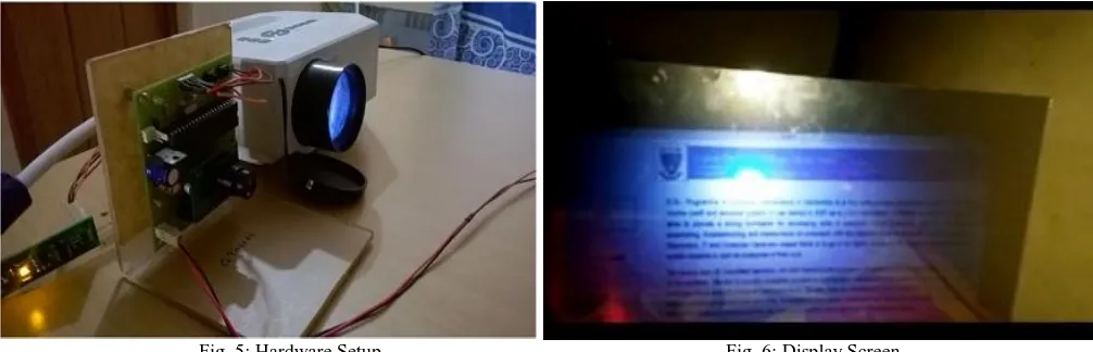
Fig. 5: Hardware Setup Fig. 6: Display Screen
Result
The project was tested successfully in the presence of teachers and students. The hardware setup was done and the project was tested for controlling the mouse pointer and performing the 'left-click' action.
The future developments that can be incorporated are:
Developing a stylus pen for 'write' and 'copy-paste' actions. Upgrading the single touch screen to a multi-touch one.
V. CONCLUSION
Touch technology has come a long way in the last decade. Just six years ago, most phones used traditional keypads; today, almost all smartphones have a touchscreen, and the technology has spread to tablets, handheld consoles and laptops as well.
Although camera-based touch detection systems appear large and complicated, they are extremely useful in cases where the size of the display is very large.
The system has several advantages such as absence of a compliant surface and LED frames, can use any transparent material as the projection surface, is slightly cheaper than other technologies and has a simple setup. However, it has many disadvantages including inability to track traditional objects and fiducials, insensitivity to pressure and may cause occlusion (in case of multi-touch) when only one laser is used. i.e. light hitting one finger blocks another finger from receiving light.
The applications of the project include user-friendly presentation boards, advertising screens, route maps etc.
REFERENCES
[1] Jain, Anjul, Diksha Bhargava Bhargava, and Anjani Rajput. "Touch-screen Technology." International Journal of Advanced Research in Computer Science and Electronics Engineering (IJARCSEE) 2.1 (2013): pp-074.
[2] Rosin, Hanna. "The touch-screen generation." The Atlantic 20 (2013).
[3] J. Hu, G. Li, X. Xie, Z. Lv and Z. Wang, "Bare-fingers Touch Detection by the Button's Distortion in a Projector–Camera System," in IEEE Transactions on Circuits and Systems for Video Technology, vol. 24, no. 4, pp. 566-575, April 2014.
[4] Katz, Itai, Kevin Gabayan, and Hamid Aghajan. "A multi-touch surface using multiple cameras." Advanced Concepts for Intelligent Vision Systems. Springer Berlin Heidelberg, 2007.
[5] Kaur, Ramandeep. "To develop an interface among C3088 camera and computer using AVR microcontroller.",unpublished [6] Hu, ZhenMuzaffar, Junaid. "Inter-Integrated-Circuit (I2C)." (2005).
[7] Gwang Jun Lee, Sang Kook Lee, Hong Kun Lyu, and Jae Eun Jang " External light Noise-Robust Multi-Touch Screen Using Frame Data Differential Method "”-IEEE journal 10.11.09/JDT.2015.2438317 , pp 750-763
[8] Marc Bender, Mark Lawford " A low-power, low-cost automotive touchscreen with real controls" – IEEE CCECE 2011
[9] Peter Brandl1, Michael Haller1, Michael Hurnaus1, Verena Lugmayr1, Juergen Oberngruber1,Claudia Oster1, Christian Schafleitner1, Mark Billinghurst2 "An Adaptable Rear-Projection Screen Using Digital Pens And Hand”, Gestures " IEEE 2007/DOI 10.1109/ICAT.2007.12
[10] Katz, Itai, Kevin Gabayan, and Hamid Aghajan. "A multi-touch surface using multiple cameras." Advanced Concepts for Intelligent Vision Systems. Springer Berlin Heidelberg, 2007.