Magnetohydrodynamic Buoyancy-Driven Flow In
Partially Active Vertical Walls Of A Square Cavity
A Shobha, C Venkata Lakshmi, K Venkatadri
Abstract: The transport properties of buoyancy-driven flow in a square cavity are studied numerically with the influence of an externally applied variable magnetic field. The vertical walls of the cavity are assumed to be partially active and the rest of the walls are thermally insulated. The solutions of the nonlinear governing differential equations which are derived by considering the effects of magnetohydrodynamic are obtained using the Marker and Cell Method (MAC). The comparison has been made with D. C. Wan and Kandaswamy’s papers to validate the present results. Effects of Rayleigh and Hartmann’s numbers on flow and heat transfer characteristics are analyzed through graphical aids in the form of streamlines and isotherms. It is to be noted that the augmentations in buoyancy force increase the thermal boundary layer thickness.
Index Terms: Finite difference, MAC Algoritm, Magnetizable Fluid, Point Magnetic Sources, Square Cavity . —————————— ——————————
1
INTRODUCTION
Generally flows can be driven by buoyancy effects or by the motion of any one or more walls of the cavity. Flow inside the cavity is an interesting aspect as it involves number of unique fluid dynamic phenomenon and has many applications in numerous engineering systems. Magnetoconvection received a great deal of attention as it has many applications in various fields such as geophysics, astrophysics, aerodynamics, engineering and industrial appliances. Moreover Magnetoconvection in cavities has wide range of applications in solar technologies, safety aspects of gas cooled reactors, crystal growth in liquids, material manufacturing technology and haemodialysis. In Ferrohydrodynamics (FHD) there need be no electric current flowing in the fluid and the body force is due to the polarization force [9]. Natural convection in a cavity with differentially heated side walls and insulated horizontal walls has been the subject of great interest. Frederick and Quiroz [1] studied the transition natural convection in a cubical enclosure with differentially heated walls. The computation carried out for the Rayleigh numbers from 103 to 105. There has been an increasing interest on the flow behaviour and the heat transfer mechanism of electrically conducting fluids in enclosures under the influence of a magnetic field [2-6]. Sathiyamoorthy and Chamkha [7] investigated the laminar two-dimensional natural convection on gallium liquid filled square enclosure in presence of inclined magnetic field with linearly heated side wall(s). They noticed that the heat transfer decreases with an increase in the magnetic field and also observed that the horizontally and vertically-applied magnetic fields affect the heat transfer differently. Sheikholeslami et al. [8] studied the influence of. a variable magnetic field on forced convection in a semi annulus. Oztop et al. [10] conducted a numerical study of natural convection in rectangular enclosure with partially heated wall.
Hasan et al. [11] examined the effect of the corrugated side wall on the natural convection of differentially heated cavity. The heat the transfer is influenced by the variation corrugation frequency and amplitude. E.E. Tzirtzilakis et al. [12] studied fundamental problem, influence of localized magnetic field on driven cavity filled with biomagnetic fluid. He noticed that polarization force alone is significant and can influence the flow field by the formation of an extra major vortex comparable to the pure hydrodynamic case. V.C. Loukopoulos et al. [13] examined numerical solution Biomagnetic channel flow in spatially varying magnetic field. Magnetization is the measure of how much the magnetic field is affecting the magnetic fluid and generally it is a function of the magnetic field intensity H and the temperature T. They observed where the magnetic source is located the vortex is arising and the temperature is increasing and no studies that investigate the variable magnetic field effects on the natural convection in air filled enclosures have been reported in the literature. Hence in this study we mainly focused on the feature of the flow and explain the flow characteristics in various conditions in presence of variable magnetic field and MAC algorithm is applied to simulate the flow. The heat transfer rate in the enclosure is evaluated in terms of the local and average Nusselt number.
2
MATHEMATICAL
MODELLING
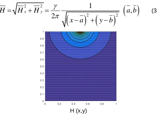
Detailed In this paper, the partially thermally active side walls of the cavity are maintained at two different but uniform temperatures are considered. Fig.1 depicts the boundary conditions. To express the magnetic field strength, one can consider that the magnetic source represents a magnetic wire placed vertical to the x-y plane at the point (a,b). The components of the magnetic field’s intensity
H H
x,
y
and strength
H
can be considered as [14].
2 2
1
2
x
H
y b
x a
y b
(1)
2 2
1
2
y
H
x a
x a
y b
(2)————————————————
• K Venkatadri is an assistant professor of Mathematics in Sreenivasa Institute of Technology and management studies,
Chittoor-517127, India. Email: [email protected] • A Shobha is Full time Research Scholar of Department of Applied
Mathematics, Sri Padmavathi Mahila Visva Vidyalyam, T AP, India • C Venkata Lakshmi is an assistant professor of Department of
4300
2 2 2 21
2
x yH
H
H
x a
y b
,
a b
(3)H (x,y)
Fig. 1. Contours of the magnetic field strength H
Where
is the magnetic field’s strength at the source (of the wire) and
a b
,
is the position where the source is located. Let us consider the unsteady two-dimensional natural convective laminar flow of fluid in a square cavity with length of side walls equal to L. The gravity acts normal to the x-axis and a magnetic source is considered by placing a magnetic wire vertically on to the x y- plane at the point
a b
,
. In this study the magnetic source is located at (0.5 columns, 1.05 rows). The thermal radiative heat flux dissipation and Joule heating are negligible. The working fluid has a Prandtl number Pr=0.71, the thermo physical properties of the fluid are assumed to be constant except the density variation in the buoyancy force, which is approximated according to the Boussinesq approximation.Fig. 2a. Physical geometry
Under the above assumptions with the Boussinesq approximation, the governing equations of conservation of mass, momentum and energy equations can be written In the Cartesian coordinate system as follows:
0
u
v
x
y
(4)2 2 2 2 2 2 0
1
y x y
u
u
u
p
u
u
u
v
t
x
y
x
x
y
H u
H H v
(5)
2 2 2 2 2 2 01
x y x c
v
v
v
p
v
v
u
v
t
x
y
y
x
y
H H u
H v
g
T
T
(6)
2 2 2
2 0 2 2 2 2 2 2 2 y x p p
T T T T T
u v H u H v
t x y x y c
u v v u
c x y x y
(7)
The following dimensionless variables are introduced
2 2 0 0 2,
,
,
,
,
,
,
( , 0)
,
,
,
2
,
x y c x y h cH H H
T
T
pL
P
H H H
T
T
H
t
x
y
H
H a
X
Y
b
L
L
L
uL
vL
U
V
(8)Using (8), Eqs. (4) – (7) can be written in dimensionless form as
0
U
V
X
Y
(9)2 2
2 2
2 2
y x y
U
U
U
P
U
U
U
V
X
Y
X
X
Y
Ha
H U
H H V
(10) 2 2 2 2 2 2x x y
V
V
V
P
V
V
U
V
X
Y
Y
X
Y
Ha
H V
H H U
Gr
(11)
2 2 2 2 2 22 2 2
1
Pr
2
2
y x
U
V
X
Y
X
Y
Ha Ec H U
H V
U
V
V
U
Ec
X
Y
X
Y
20 0 2
3 2
,
Pr
,
p
h c
Ha
L
H
Ec
c
TL
g
T
T L
Gr
The appropriate boundary conditions for the problem are On the left wall of the active part
1
On the right wall of the active part
0
On all the remaining part of the walls
0
n
On all wallsU
V
0
The local Nusselt number on the heat source surface can be obtained as
0
Y
Nu
X
The average Nusselt number
1
h
Nu
Nu dY
h
Where2
L
h
Flow field of fluid in the present problem is visualized through streamline which is obtained from stream function. Stream function is defined from velocity components U and V. The two-dimensional flow stream function and velocity components Relations are given by
,
U
V
Y
X
(1)
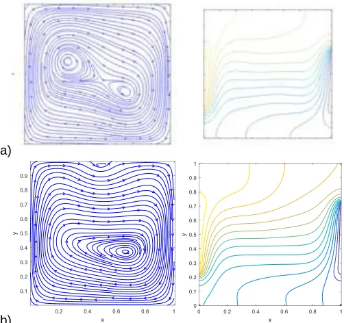
Fig. 1. Code validation study, comparison of streamlines u-velocity, v-velocity and isotherms with D. C. Wan et al. [15] Ra = 104 and Pr=0.7. (a) D. C. Wan et al. [15], (b) Present solver
(MAC)
Table 1
Result of grid independence test.
Gride Size Nuavg
41X41 1.344738 61X61 1.367323 81X81 1.380034 101X101 1.380421 121X121 1.393697
b)
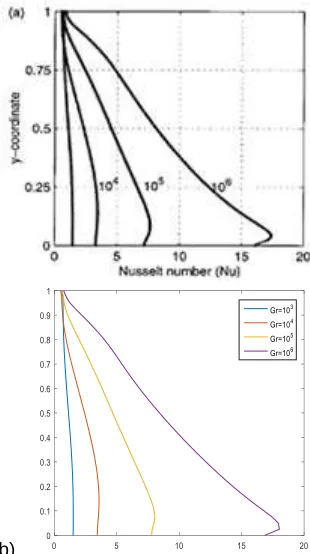
Fig. 4. Comparison of Local Nusselt number variation of hot wall for 103<Ra<106 (a) D. C. Wan et al. [15], (b) Present
solver (MAC)
3 COMPUTATIONAL
DETAILS
3.1NUMERICAL PROCEDUREAs The MAC method has been used for the numerical scheme of the specified problem. The coupled governing equations were converted into weak form. The staged grid system is used for solving Navier Stokes equation while the central difference scheme is used to solve energy equation. We integrate in time by an incremental step in each iteration until the final time 1.0 is reached. Iterative technique is used to solve the resulting equations. The solution process was sustained until the required convergent criterion was full-filled which was 1 6
, , ,
10
k k
i j i j
i j
the generic variable.
stands fo U V P
r
,
,
,
k denotes the iteration time levels. In the above inequality the subscripts i, j represents the space coordinates X and Y respectively.
3.2 GRID INDEPENDENCY TEST
To allow grid independent test, the numerical computation has been conducted for various grid sizes. Table 1 demonstrates the influence of grid size for a test case confined within the present configuration. The results show that 81X81 grid size is good enough to obtain accurate results.
3.3 GRID INDEPENDENCY TEST
4302
are compared for Ra=104 and Pr=0.7 as shown in Fig. 3. From the figure it is evident that the streamlines and isotherms produced by the present code are matched with previously published work by D. C. Wan et al. [15]. Also the Local Nusselt number of hot walls is compared for different values of Gr as shown in Fig.4. The error is very negligible if the Nusselt number is compared. The comparisons reveal an excellent agreement with the reported studies, and hence the present numerical code is completely reliable.
4 RESULTS
AND
DISCUSSION
The influence of variable magnetic field on the buoyancy-driven convection of an air filled square cavity with partially active side walls is examined numerically. The heated location and cooled location are always maintained on the left wall and on the right wall respectively. The flow field and isotherm gradients inside the square cavity are depicted and discussed under the effect of magnetic source also the heat transfer characteristic is examined with nine different active locations.
a)
b)
Fig. 5. Steady state streamlines and isotherms for midle-midle active location, Pr = 0.71, Ha = 10 and Gr = 105 (a) the magnetic field is applied parallel to gravity (b) magnetic source is located at (0.5 columns, 1.05 rows, EC=10-5.
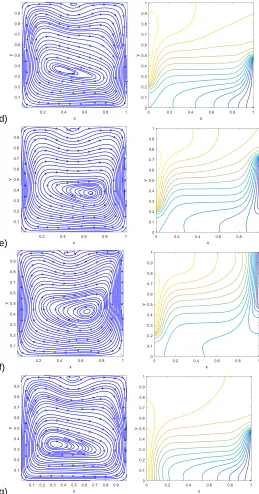
Figure.6. illustrate the streamlines and isotherms for nine different combinations of active locations with magnetic
a)
b)
c)
(Continue)
Fig. 6. Steady state streamlines and isotherms for Pr = 0.71, Ha = 10 and Gr = 10-5 (magnetic source is located at (0.5
columns, 1.05 rows)).
d)
e)
f)
g)
(Continue)
Fig. 6. Steady state streamlines and isotherms for Pr = 0.71, Ha = 10 and Gr = 10-5 (magnetic source is located at (0.5
columns, 1.05 rows)).
in Fig. 6g. The corresponding isotherms in Fig. 6c and 6g show the convective mode of heat transfer is more at the active positions and the bottom and top of the square cavity are thermally inactive. In the middle-bottom active position case in Fig. 6d a minor and major clockwise vortices are seen. The major vortex is appeared at the hot location and the minor vortex is appeared at the top wall and the corresponding isotherms indicate that the fluid particles transport the energy by convection mode which is meagre at the top of the enclosure.
h)
i)
Fig. 6. Steady state streamlines and isotherms for Pr = 0.71, Ha = 10 and Gr = 10-5 (magnetic source is located at (0.5
columns, 1.05 rows)).
Fig. 7. Mid-height velocity profiles for top-bottom active location, Pr = 0.71, Gr = 105 and EC=10-5.
4304
small vortex is exist at middle of top wall in Fig. 6i is observed. The isotherms contours are formed thermal boundary layer near the active zones. The decrease in mid-height velocity for the increase in the Hartmann number is shown in Fig. 7 for top-bottom active location, it observed that the fluid particle velocity decreases with increasing the Hartmann number. The central line u velocity is shown in Fig. 8 for top-bottom active location. It is noticed that the oscillating flow in the upper half of the enclosure is decreasing strikingly with increase in the Hartmann number.
Fig. 8. Mid-width velocity profiles for top-bottom active location, Pr = 0.71, Gr = 10-5 and EC=10-5.
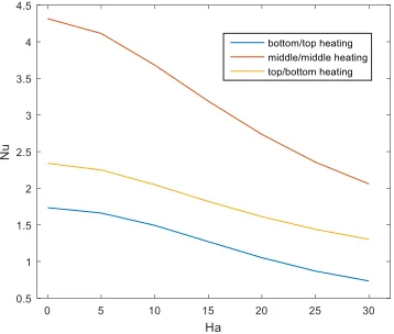
Fig. 11 exhibits the average Nusselt number for three different active locations for various Hartmann numbers for Pr = 0.71, Gr = 105 and EC=10-5. As expected when the Hartmann number increases the average Nusselt number decreases, but the rate of heat transfer is high in the middle–middle active locations and low for bottom-top active locations. The influence of the Hartmann number (Ha) on mid-height and mid-width velocity profiles for top-bottom active location are presented in Fig. 7 and Fig. 8 respectively for Pr = 0.71, Gr = 105 and EC=10-5. The mid-height velocity profile is enhanced when the Hartmann number is decreases are shown in Fig 7. The U- velocity along the vertical centerline of the enclosure for top-bottom active location with various values of Ha presented in Fig. 8. The variation of velocity is increases along vertically from bottom to top, the velocity variation is noticed more upper of the enclosure but the mid-width velocity decreases with increasing of Hartmann number (Ha). Fig. 9 and Fig. 10 delineate variation of U- velocity profile along the vertical centerline in cavity for Ha=0 and Ha=30 with different active locations, mainly observe U-velocity profile for top-bottom, middle-middle and bottom-top active locations. The velocity increases with the active location moving from top to bottom are shown in Fig. 10. The velocity variation is observed more for bottom-top active location (Fig. 9c) and also low velocity variation is noticed for Ha=0 and Ha=30 for top-bottom active location (Fig. 9c).The magnetic field effect (Ha=30) on horizontal velocity profile, the velocity curve shifted from wave form to linear curve. This change observed clearly near top wall/upper half of the cavity.
a) b)
c)
Fig. 9. Mid-width velocity profiles for Pr = 0.71, Gr = 105 and EC=10-5 (a) top-bottom active location (b) middle-middle active
location (c) bottom-top active location.
(1)
Fig. 10. The U- velocity profile along the vertical centerline of the cavity with different active locations for Pr = 0.71, Gr = 105
and EC=10-5.
Fig. 11. Average Nu vs Ha for different active locations, for Pr = 0.71, Gr = 105 and EC=10-5 .
to other cases.
5 CONCLUSIONS
Natural convection in air filled square enclosure with partially active vertical wall in presence of Point magnetic source is fixed at top wall is studied numerically with nine different combinations of active zones. It is notice that in all combinations the fluid flows in a curvy nature near the magnetic point source. The single enlarged eddy is forming inside the enclosure with the impact of top thermal active case. The minor vortex is formed at centre of top wall for the case of middle active thermal zone and the fully developed minor vortex is formed for the active thermal zone set at bottom location. The flow velocity increases when the heating location changing from top to bottom. As the Hartmann number (Ha) is increased convection is suppressed and the heat transfer in the cavity is decreases, but the rate of heat transfer is more for middle-middle heating location. The average Nusselt number is decreases for increasing of Hartmann number (Ha).
6
REFERENCES
[1] R.L. Frederick, F. Quiroz, ―On transition from conduction to convection regime in a cubical enclosure with a partially heated wall‖ International Journal of Heat and Mass Transfer vol. 44, pp. 1699–1709, 2001.
[2] H. Ozoe, K. Okada, ―The effect of the direction of the external magnetic field on the three-dimensional natural convection in a cubical enclosure‖, International Journal of Heat and Mass Transfer vol. 32, no. 10, pp. 1939-1954, 1989.
[3] J.P. Garandet, T. Alboussiere, R. Moreau, ―Buoyancy driven convection in a rectangular enclosure with a transverse magnetic field‖, International Journal of Heat and Mass Transfer vol. 35, no. 4, pp. 741-748, 1992. [4] M. Venkatachalappa, C.K. Subbaraya, ―Natural convection
in a rectangular enclosure in the presence of a magnetic field with uniform heat flux from the side walls‖, Acta Mechanica vol. 96, no. 4, pp. 13-26, 1993.
[5] S. Alchaar, P. Vasseur, E. Bilgen, ―Natural convection heat transfer in a rectangular enclosure with a transverse magnetic field‖, Journal of Heat Transfer vol. 117, no. 3, pp. 668-673,1995.
[6] N. Rudraiah, R.M. Barron, M. Venkatachalappa, C.K. Subbaraya, ―Effect of a magnetic field on free convection in a rectangular enclosure‖, International Journal of Engineering Science vol. 33, no. 8, pp. 1075-1084, 1995. [7] M. Sathiyamoorthy, A. Chamkha, ―Effect of magnetic field
on natural convection flow in a liquid gallium filled square cavity for linearly heated side wall(s)‖, International Journal of Thermal Sciences vol. 49, no. 9, pp. 1856-1865, 2010.
[8] M. Sheikholeslami , K. Vajravelu , M.M. Rashidi , ―Forced convection heat transfer in a semi annulus under the influence of a variable magnetic field‖, International Journal of Heat and Mass Transfer vol. 92, pp. 339–348, 2016.
[9] Rosensweig RE. Ferrohydrodynamics. Mineola, New York: Dover Publications; 2014.
[10]Oztop, H. F., and Abu-Nada, E., ―Numerical Study of Natural Convection in Partially Heated Rectangular Enclosures Filled with Nano fluids,‖ International Journal of Heat Fluid Flow, vol. 29, no. 5, pp. 1326–1336, 2008. [11]Hasan, M. N., Saha, S. C., and Gu, Y, ―Unsteady Natural
Convection Within a Differentially Heated Enclosure of Sinusoidal Corrugated Side Walls,‖ International Journal of Heat and Mass Transfer, vol. 55, pp. 5696–5708, 2012. [12]E.E. Tzirtzilakis, M.A. Xenos, ―Biomagnetic fluid flow in a
driven cavity‖, Meccanica , vol. 48, pp. 187–200, 2013. [13]V.C. Loukopoulos, E.E. Tzirtzilakis, ―Biomagnetic channel
flow in spatially varying magnetic field‖, International Journal of Engineering Science vol. 42, 571–590, 2004. [14]E.E. Tzirtzilakis, M. Xenos, V.C. Loukopoulos, N.G.
Kafoussias, ―Turbulent biomagnetic fluid flow in a rectangular channel under the action of a localized magnetic field‖, International Journal of Engineering Science, vol. 44, pp. 1205–1224, 2006.