REDUCE REROUTING TIME IN MANET USING VIRTUAL
BUFFER ZONE ALGORITHM
Mr.Umakant S. Shirshetti, Prof.Mr.G.T. Chavan
Department of Computer Engineering
Sinhgad College of Engineering, Pune, Maharastra, INDIA
Abstract— The high mobility of nodes in mobile ad hoc networks
(MANETs), there exist frequent link breakages which lead to frequent path failures and route discoveries. MANET routing protocols have to deal with link breaks, which occur due to the frequent movement of the nodes and a dynamic network topology. The latency that occurs during this retransmission is referred to as rerouting time. There are several researches have been proposed by different authors to enhance the rerouting time. One such approach is the buffer zone routing, where the transmission area of a node is isolated into a safe zone near to the node, and an unsafe zone close to the end of the transmission range. Be that as it may, this methodology has a couple of limitations and constraints, such as buffer zone size and network load etc. In this we propose a enhance buffer zone transmission, where the nodes within this buffer forms a virtual zones by considering node energy level. However this paper enhance this study by introducing virtual zone into unsafe zone by considering an energy aware reactive routing technique based on existing reactive protocols. The introduction of virtual zone increases the network performance. The proposed mechanism decreases the rerouting time and it recusehop length. The proposed experiment is conducted in NS3 to analyze the performance.
Index Terms— MANET, Routing, Rerouting Time, Buffer Zone, Virtual zone, Energy Aware Routing Protocol
I. INTRODUCTION
The process of increasing wireless devices have made MANET’s a suitable exploration topic. Large number of self forming, self healing wireless devices formed network. It has routable network environment on top of link layer. Similar to MANET numerous wireless communication model established globally as Vehicular Ad hoc Networks (VANETs) , Internet based mobile ad hoc networks (iMANETs), Smart Phone Ad hoc Networks (SPANs) etc.
The chief importance of routing protocol is to find and maintain route between sources to destination. In MANET, progressively changing topology causes link failure leads to affects the network connectivity often and invalidate entire route. When a link break in an active route occurs the very
most challenging concern in MANET is routing packets from one another. Besides, the nodes are calculated on the limited battery power and bandwidth as resources. A lack of power in any node and changes their places thru the movement may result in network separation.
The goal of any routing protocol is to build upon route between any two nodes to send data packets and maintain routes to needed network destinations.
This can be classified as:-
1. Reactive routing - On-Demand 2. Proactive routing. - Table - Driven
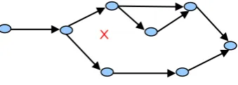
Proactive routing has the route always available before transferring data packets from source to destination. All nodes keep updating and maintain entire routing information report of the network. The most common proactive routing protocols are Destination Sequenced Distance vector DSDV and Optimized Link State routing OLSR. In reactive routing the routes to the destination are discovered only when actually needed. This paper proposes proactive routing protocol. Due to dynamic change of network link between nodes are not permanent. Fig 1 shows the link disconnection in wireless network. In this situation node cannot send packet to its next hop as a result packet may be lost. Loss of packets may affect route performance. Each node act as routers for any ongoing packet communication and have limited transmission ranges. Once a route is found, the node uses it until the destination is reached or the route expires. Due to mobility or energy loss, node goes away from the path or it may expire. Thus link breaks, when a link breaks data transfer is stopped [4].
Impacts of link failures:-Network partitioning, Bandwidth Oscillations, Increasing Packet loss, Link recovery increases delay and jitter, rerouting time.
In such instance, the routing protocol has to find new path. The time period before new paths are found is referred to as the rerouting interval called as rerouting time. During the rerouting interval, stale routes exist over the link that has been broken. Rerouting can take place only after the routing protocol has detected that the link is broken. In fact, a significant part of the rerouting time is associated with the detection of the link break. In summary, the rerouting time due to link breaks depends on the time to carry out the following processes:-
Link Failure detection
Remove all stale packets from the output queue
Network-wide link-state announcement to construct new paths
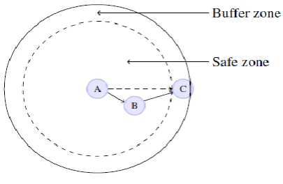
The Buffer zone routing protocol divides the communication region of a node into a safe zone close to the node, and an unsafe zone (i.e. buffer zone) near the end of the transmission range. Nodes located in the buffer zone have high probability to disconnect with neighboring nodes. So that link failures take place, meanwhile links to neighboring nodes in the safe zone are expected to be more stable. To avoid network partitioning safe zone nodes are preferred as relay nodes, while nodes in the buffer zone are only used if required.
To reduce rerouting time and avoid link failure, a solution has been proposed to the advancement of this approach. The major contribution of this paper to minimize the drawback of buffer zone routing. The key idea is to divide the safe zone in to multiple virtual zones based on the distance, energy and transmission range of the nodes. With the current approach, the unsafe or buffer zone is not considered.
The rest of the paper is structured in the following way. First, Section II provides the Existing Methodologies, In background the OLSR Environment, Zone Routing , rerouting is discussed in section III. The proposed approach is presented in Section IV, along with benefits. Simulation results are provided in Section V, with the performance analysis charts of the Buffer and Virtual zone algorithm. Finally, in Section VI Conclusion with future work explained,
II. BACKGROUND
2.1 OLSR Environment
A proactive approach to MANET routing seeks to maintain a constantly updated topology understanding. The whole network should, in theory, be known to all nodes.[4] This results in a constant overhead of routing traffic, but no initial delay in communication. It is a table-driven pro-active protocol. As the name suggests, it uses the link-state scheme
in an optimized manner to diffuse topology information. In a classic link-state algorithm, link-state information is flooded throughout the network. OLSR uses this approach as well, but since the protocol runs in wireless multi-hop scenarios the message flooding in OLSR is optimized to preserve bandwidth. The optimization is based on a technique called Multipoint Relaying MPR. Being a table-driven protocol, OLSR operation mainly consists of updating and maintaining information in a variety of tables. The data in these tables is based on received control traffic, and control traffic is generated based on information retrieved from these tables. The route calculation itself is also driven by the tables. OLSR defines three basic types of control messages
HELLO - HELLO messages are transmitted to all neighbors. These messages are used for neighbor sensing and MPR calculation.
TC - Topology Control messages are the link state signaling done by OLSR. This messaging is optimized in several ways using MPRs.
MID - Multiple Interface Declaration messages are transmitted by nodes running OLSR on more than one interface. These messages list all IP addresses used by a node.
2.2 Zone Routing
Zone routing is a mechanism to reduce the disadvantages of shortest path routing in MANETs. The key idea is to divide the transmission area of a node into a safe zone close to the node and an unsafe zone (i.e. buffer zone) near the end of the transmission range Fig.2 shows.
Fig 2: Transmission Zone Area
with safe zone nodes to forward data and in case if network partitioned choose unsafe zone to forward packet.
2.3 Rerouting
Wireless networks use some sort of radio frequencies to transmit and receive data. The info about the active neighbors for this route is maintained by each node through the routing table.Problem in wireless communication is link disconnection due to mobility or energy loss. So the topology is changed or the links in the active path are broken. Link failure can be determined as the ratio between the powers of the transmitted signal to the receiver signal between neighbors during communication. Re-initializes the path discovery if source still desires the route for alternate. The time period before new paths are found is referred to as the rerouting interval, and the duration of the rerouting interval is referred to as the rerouting time.
III. EXISTINGMETHODOLOGIES
It is a necessity for every network to have some form of communication where the delivery of the packets to the destination is guaranteed. This paper is a follow up of [4], where an analysis of MANET link failures and metrics was performed. However, due to node mobility, link failures in such networks are very frequent and render certain standard protocols inefficient resulting in wastage of power and loss in throughput. As a result, routing in such networks experiences link failure more often. Other works such as method of link failure prediction and consequently execute a rapid local route repair discussed [2] mainly propose packet dropping rate and end-to-end delay and maximize packet delivery ratio as a result.
R. Senrhil Kumar, Dr. C. Sureshkumar [6] present a novel method to Minimizing the Route Rediscovery Process based Protocol.. This paper selects the more stable route and reduces the link break. . It also uses Received Signal Strength(RSS) based to minimizing the route rediscover process and the optimization of flooding process , based on Time-to-Live (TTL) value , reducing route rediscovery process solution to accomplish the link failure
.
[4] Main objective of this paper is to study the route instability in AODV protocol and suggest a solution for improvement. This paper proposes a new approach to reduce the route failure by storing the alternate route in the intermediate nodes. In this algorithm intermediate nodes are also involved in the route discovery process
Concept of handoff could be used in contexts other than link failure. if a node that is low on power, a node that knows it is
going to switch off could handoff without affecting the rest of the ad hoc network. It might also be interesting to incorporate Router Handoff into other ad hoc routing protocols [6] paper reduces path fail correction messages and can improve the robustness .of performance. Therefore, success rate of route discovery may be increased even though high node mobility situation. The introduction of a transmission buffer zone in OLSR gives an improved throughput, compared to the standard OLSR. The advantage of using a buffer zone is observed both for low and high traffic
To handle packet losses caused by node mobility or energy loss, the existing buffer zone routing protocol does not provide much solution. Using OLSR proactive routing protocol this paper modifies buffer zone routing protocol.
Santivanez et al. worked on the scalability of Ad Hoc Routing Protocols [3]. They defined scalability and conducted an analytical study on scalability of various routing protocols like PF, SLS, DSR, HierLS, ZRP and HSLR with respect to network size, mobility, and traffic. Authors analysed that HSLS protocol outperformed HierLS protocol in term of scalability. Chipara et al. proposed a Real-time Power-Aware Routing protocol for wireless sensor networks [2], which used dynamic power adaptation algorithm and achieved application required delay. This protocol improved the power consumption aspect with respective to other energy efficient protocols.
Doshi et al, proposed a minimum energy on-demand (reactive) routing protocol for Ad-hoc networks [5]. They discussed and implemented features like route energy cost comparison to select best route, transmission power control and minimum energy route discovers to conserve energy. They highlighted the importance of efficient catching techniques to store the minimum energy routeing information. Authors tested there protocol by conducting a simulation and also in real-time test bed containing wireless cards and laptops. Bilandi et al, conducted an analysis of existing six popular routing protocols based on user’s point of view [10]. They simulated AODV, DSR, LAR, OLSR, STAR and ZRP protocol using QualNet simulator and analysed packet delivery ratio, throughput, end-to-end delay, battery power consumption, average hop count for connection, packets drop, and average jitter for receiving packets. Their analysis shows that the reactive routing protocols consume less energy compared to proactive or hybrid protocols.
IV. PROPOSEDMODEL
Queuing delay is the time a of data packet waits in a queue until it can be executed. It is a key component of network delay. This also may affect rerouting time. Large queue size leads packet-dropping due to packet life time and also because of stale route information. Mobile adhoc network performance determined by node energy level, speed, coverage area, topology size, transmission and receiving energy, network load these are all affect the rerouting time.
If network size increased hop length also increased is the risk. Multiple virtual zone in safe zone provides solution for rerouting time reduction. The protocol supports node mobility can be monitored through its local control messages.
4.1 Multi Point Relay Message MPR- Formations
Main idea of MPR is reducing duplicate re-transmission in coverage area, this controls to broadcast and flood the packet in network. Each node selects set of nodes called MPR from its one hop neighbors to re-transmit its packets. If node not as MPR in neighbor set will not re-transmit the packets. If node receives packets from MPR assumed to be re-transmitted by that node. This MPR nodes change over a time as per topology modification. This MPR status indicate by the hello message. Each node its two hop neighbors must have bi-diractional link towards MPR. Using MPR each node update its route to known destinations. Each node maintains MPR list and update periodically. If a node which covers maximum of two hop neighbors act as MPR for that HELLO interval.
4.2 HELLO Message
Every refreshing interval once HELLO message exchanged between one hop nodes and update fresh neighbor list. Each node perform to select MPR among its one hop nodes and this MPR indication exchange thru HELLO message. Also each node learn the knowledge of two hop neighbor list .Each node maintains one hop list, two hop list, link status. Periodically invalid entries removed from this list. End of this list update each node aware of its one hop, two hop and MPR node knowledge[4]. As a proposed method while exchange Hello message send virtual zone information also for updating routing table. Depends on topology change dynamically virtual zone also re-formed. All the node movement information send thru HELLO message so that refresh neighboring list and virtual zone list.
4.3 Topology Control Message – TC Message
Each node send TC message with MPR node information. It contains list of neighbor and MPR records. These information used to construct topology table. If node does not have any knowledge about MPR will not send TC message. If changes in network next TC message hold that information.
4.4 Virtual zone formation.
Split safe zone area into multiple virtual zones. This virtual zones may change dynamically as per topology changes. Each virtual zone has group of nodes. Along with virtual zone information each node update their routing table. This minimize rerouting time and hop length also minimizes the routing decision thus saves energy consumption.
Compute virtual zone _size =(node-coverage * safe_range) / number of virtual zone
compute xpoint of node = XPOINT – zone_size ypoint of node = YPOINT – zone_size
Fig 3 Safe Zone divided as virtual zone
4.5 virtual zone routing
Check zone table and number nodes in zone. If nodes available check node from current zone to next zone to forward data packets . Choose minimum distance node as next hop and update routing table till reach destination.
V. SIMULATIONSTUDY
Simulation done in NS2 platform. Buffer zone algorithm improved with virtual zone based routing presented here. Network tested with different performance metrics of packet size, simulation time and number of traffic increases in network.
5.1 Packet delivery ratio with packet size
The ratio is calculated by how many data packets effectively delivered to destination from source. Packet delivery ratio generated by the sources node and it can be accurately written as
PDR = p - received / p – sent
Fig.4 Packet size with PDR
Fig.4 illustrate the proposed virtual zone based network shows high packet delivery ratio than bufer zone routing potocol.
5.2 Jitter with Packet size
Consecutive packet gap duation at destination end veriffied and compaed with virtual zone routing and bufffer zone routing protocols.
Fig.5 Jitter with Packet Size
Fig.5 shows virtual zone minimizes the jitter delay while receiiving this improves network performance.
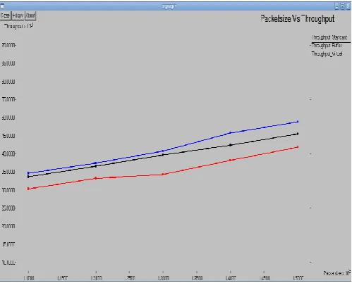
5.3 Throughput with Packet size
In throughput graph as the figure illustrated the throughput of the new and previous protocols. X axis shows Packets and y axis shows the throughput.
Fig.6 Throughput with Packet size
5.4 Throughput with Traffic
Peroformance of throughput also high while incerasing data taffic in network with virtual zone fofrmation. Because of rerouting time minimization data packet flow increased .
Thoughput = Aerage packet size * 8 / data duation
Fig.7 Throughput with Traffic
5.5 Simulation Results
Table 1 summarizes the simulation parameters used
Table 1. Simulation /parameter
The above said results achieved using Table-1 parameters. By varying the simulation parameter values still the protocol can produce good performance.
5.6 Proposed System Structure
VI. CONCLUSION
Due to dynamic network the connectivity between nodes is interrupt commonly. A proposed virtual zone within the buffer zone in the OLSR gives an throughput and Packet delivery ratio. The rerouting time is also very much reduced when communication arise inside virtual zones.
The proposed concept is simulated using NS 2.34, and testing perform to show, that there is an enhanced result due to the introduction of the virtual zones. Evaluation graphs are also provided to show, that the rerouting time is condensed with the initiation of the virtual zones. The increase in the hop length was a foremost shortcoming of the buffer zone. The study shows that it was minimized after introducing the virtual zones
.
REFERENCES
[1] Manet simulation and implementation at the university ofmurcia (masimum). http://masimum.dif.um.es/.
[2] Network simulator 2 – ns2. http://nsnam.com
[3] U.S. Shirshetti, G.T. Chavan An Enhanced Reactive Routing to Reduced Rerouting Time with Enhaced Buffer Zone approach in MANETs international Journal Engineering Reserch and Technology, ISSN-2278-0181 vol IV,issue 04.April 2015pages 15–20, 2015.
[4] M. Benzaid, P. Minet, and K. Al Agha.Analysis and simulation of fast-olsr. The 57th IEEE Semiannual Vehicular Technology Conference (VTC), 3:1788–1792, April 2003. [5] G. Chauhan and S. Nandi.Qos aware stable path routing (qasr) protocol for Manets. First International Conference on Emerging Trends in Engineering and Technology (ICETET), pages 202–207, July 2008.
Parameters Values
Simulation area (x) 500 mtr
Simulation area (y) 500 mtr
Simulation time 200.0 seconds
Number of nodes 50
Transmission power TxPower 0.2mw
Receiving power RxPower 0.1mw
Routing Protocol EBZAR
Antenna OmniAntenna
packet_Size 512 bytes
Interval 0.1seconds
macType 802_11
FORM-MPR
Send TC Message
Receive TC Message
Send MID if More Then 1 Interface
Receive MID
Start Virtual Zone Formation
[6] Charu Gupta and Pankaj Sharma, “An Approach to Link Failure in MANET ” IJCSNS page 1 -3, 2014.
[7] K.-W. Chin. The behavior of Manet routing protocols in realistic environments. Asia-Pacific Conference on Communications, pages 906–910, Oct. 2005.
[8] K.-W. Chin, J. Judge, A. Williams, and R. Kermode. Implementation experience with manet routing protocols.SIGCOMM Computer Communication Review, 32(5):49–59, 2002.
[9] T. Clausen, P. J. (editors), C. Adjih, A. Laouiti, P. Minet,P. Muhlethaler, A. Qayyum, and L.Viennot. Optimized link state routing protocol (OLSR).RFC 3626, pages 1–75, October 2003. Network Working Group.
[10] S. Crisostomo, S. Sargento, P. Brandao, and R. Prior.Improvingaodv with preemptive local route repair. International Workshop on Wireless Ad-Hoc Networks, pages223–227, 2004.
[11] T. Goff, N. B. Abu-ghazaleh, D. S. Phatak, and R. Kahvecioglu.Preemptive routing in ad hoc networks.ProceedingsACM/IEEE MobiCom, pages 43–52, 2001.
[12] IEEE. Wireless LAN medium access control (MAC)and physical layer (PHY) specification.IEEE standard802.11, June 1999.
[13] H. Lundgren, E. Nordstr¨o, and C. Tschudin. Coping with communication gray zones in IEEE 802.11b based ad hocnetworks. In Proceedings of the 5th ACM international workshop on Wireless mobile multimedia (WOWMOM), pages 49–55, New York, NY, USA, 2002. ACM.