Theoretical Analysis of a Dual- Pumped
Multi-Segment Photonic Crystal Fiber Optical Parametric
Amplifier
Kumbirayi Nyachionjeka 1,*, Hillary Tarus 2 and Kibet Langat 3
1Pan African university (PAUSTI), Nairobi, Kenya, e-mail: [email protected]
2West Indian Ocean Cable Company, Nairobi, Kenya, e-mail: [email protected]
3Electrical Engineering Department, Jomo Kenyatta university of agriculture and technology, e-mail: [email protected]
1, * Correspondence author: [email protected]
Abstract— Further research work still needs to be done in efforts to achieve a practically feasible fiber optical parametric amplifier. Uniform gain in a gain spectrum is still a challenge because of the gain ripples in a given bandwidth. While, the cost and losses of the amplifier due to length, type of the fiber and the pump powers are challenges that still need to be reduced. A dual – pumped multi-section fiber optical parametric amplifier design based on two types of photonic crystal fiber with different dispersion slopes is proposed. Lengths of a photonic crystal fiber with a positive dispersion slope shall be cascaded together with a photonic crystal fiber with a negative dispersion slope to try and achieve uniform amplification over the target bandwidth and shorter amplifiers. The amplifier is theoretically demonstrated and it leads to a gain of 38-dB over a gain bandwidth of 280-nm with a ±0.13-dB flatness and combined fiber length of 82.2-m and reduced pump power.
Index Term— Dual-pump, FOPA, Gain spectrum, HNLF, Multi-section, negative dispersion slope, photonic crystal fiber, segments.
1. INTRODUCTION
For fiber optical parametric amplifier (FOPA) to be of practical use in fiber optical communication networks and systems there is need for the amplifiers to provide broad, flat gain spectrum, high gain, and reduced FOPA cost. FOPAs have the advantage of amplifying signals at any wavelength, high phase sensitivity, large gain bandwidth etc. [1-4].
Much of the research in multi-section FOPA amplifiers has been done using the high non-linear fibers (HNLFs) with low non-linear parameters and mostly relying on single pump for amplification which results in none uniform amplification with high bandwidth and long length of fibers being required for a design [3-5]. Dual- pumped multi-section HNLF have been demonstrated in research [4- 6], flat gain bandwidth of up to 346-nm and high gain of 60-dB were achieved with relatively longer length of at least 1km.
Photonic crystal fibers (PCFs) have become an alternative to HNLFs in FOPA design, because of their higher nonlinearity parameters which ensure use of shorter fiber lengths, less pump power to achieve higher gain and broad bandwidth, lower dispersion, and high birefringence. Use of short PCF length leads to a reduction in the overall losses and
the FOPA [1]. One –pump FOPAs based on PCFs have been demonstrated and have shown higher gain and considerably wider bandwidth, when compared to single-pump HNLF FOPA [7].
Employing two types of fiber in FOPA designing has been demonstrated, Gao et al presented a one-pump three-section HNLF-DCF (dispersion compensating fibers) amplifier. The DCFs where meant to improve the gain characteristics of the amplifier by compensating the chromatic dispersion arising from each HNLF and a 220 nm bandwidth with a peak gain of 16.9 dB was realized [8]. Dual pump based on cascaded PCF sections have shown even broad and flat gain spectra when compared to one-pump PCF FOPAs. Mingyi Gao et al [9], designed a dual-pump three-section PCF FOPA and this provided a theoretical near flat bandwidth of 21.54-dB with a ripple of 0.2-dB over a 405-nm bandwidth with a pump power was of 1W.
In this work we sought to compare with existing dual-pumped multi-section FOPAs made from HNLFs and DCFs while using the concepts used in realized by Cao et al. [1]. We theoretically investigated the gain spectrum and the gain peak of the FOPA design made up of PCF segments with different dispersion slopes. Focus was put on the flatness of the gain, length of fiber, pump power, while taking into consideration the loss in the fiber. The results in this work, indicate that the proposed dual-pumped FOPA can attain flatter and wide-gain spectra and high peak gain using reasonably low pump power and short length of fiber when compared to the HNLF based multi-section FOPAs as observed by Jie Gao et al. [8] and by Mingyi Gao et al. [9] and other multi-section PCF FOPAs.
2. MATERIALS AND METHODS
Considering the fibre loss, we have four continuous waves (CWs) in the first segment of the PCF which constitute an
electric field. These waves are at frequencies
𝜔1, 𝜔2, 𝜔3 𝑎𝑛𝑑 𝜔4 . The four separate waves interact with
each other under the conditions, 𝜔1+ 𝜔2= 𝜔4+ 𝜔3. .
While, 𝜔1 and 𝜔2 are used as pumps and 𝜔3 𝑎𝑛𝑑 𝜔4 are
used as signal and idler respectively. Idler arises when the
signal respectively. Linear wave-vector mismatch is given Δβ for the PCF.
The coupled equations given in [10-11] reduce to the coupled equations in equation (1-4) after taking into consideration the
following assumptions, assuming attenuation factors are equal, pump powers remain far much larger than the signal and idler at all times and the losses of the pumps are considered negligible.
𝑑𝐴1
𝑑𝑧 +
𝛼
2𝐴1= 𝑖𝛾[|𝐴1|
2+ 2(|𝐴
2|2)]𝐴1 (1)
𝑑𝐴2
𝑑𝑧 +
𝛼
2𝐴2= 𝑖𝛾[|𝐴2|
2+ 2(|𝐴
1|2)]𝐴2 (2)
𝑑𝐴3
𝑑𝑧 +
𝛼
2𝐴3= 2𝑖𝛾[(|𝐴1| 2+ |𝐴
2|2)]𝐴3+ 2𝑖𝛾𝐴1𝐴2𝐴4∗𝑒−𝑖∆𝛽𝑧 (3)
𝑑𝐴4
𝑑𝑧 +
𝛼
2𝐴4= 2𝑖𝛾[(|𝐴1| 2+ |𝐴
2|2)]𝐴4+ 2𝑖𝛾𝐴1𝐴2𝐴3∗𝑒−𝑖∆𝛽𝑧 (4)
𝑧 is the distance from the beginning of the first section PCF, where
𝑃𝐽𝑒−𝛼𝑧 = |𝐴𝑗| 2
(5)
𝑗 = 1𝑜𝑟 2 are the pump powers at z. P is the power and equation (5) depicts the relation between the power and the complex amplitudes.
In this analysis, the fibre is considered as a cascade of (𝑚 + 1) PCF sections separated by 𝑚 – negative dispersion sloped PCF
(n-PCF) sections, each one with a relatively small length, making its contribution in terms of loss negligible. After a number of steps equations for 𝐵4∗and 𝐵3 can be derived from equation (1-4) to yield the following general equations;
𝐵3(𝑧) = (𝐶1𝑒𝑔𝑧+ 𝐶2𝑒−𝑔𝑧)𝑒𝑥𝑝[(𝛼 − 𝑖𝐾)𝑧 2⁄ ] (6)
𝐵4∗(𝑧) = (𝐶3𝑒𝑔𝑧+ 𝐶4𝑒−𝑔𝑧)𝑒𝑥𝑝[(𝛼 + 𝑖𝐾)𝑧 2⁄ ] (7)
Applying the initial conditions at the input of the fibre 𝑧 = 0. The transfer matrix for the system of fibre is obtained as
[𝐵3𝑙
𝐵4∗𝑙
] = 𝑒−𝛼𝑙2 [ 𝑎 𝑏
𝑏∗ 𝑎∗] [
𝐵3(0)𝑙
𝐵4∗(0)𝑙
], 𝑛 = 0,1,2 … 𝑘 − 1 (8)
With the entries for the matrix easily shown to be equation (9) and equation (10)
𝑎 = 𝑒(𝛼+𝑖𝑘)𝑧2 [cosh(𝑔𝑧) +(𝛼+𝑖𝐾) 2
sinh (𝑔𝑧)
𝑔 ] 𝑒
𝑖 (𝑥) 𝑧 (9)
𝑏 = 𝑒−(𝛼+𝑖𝐾)𝑧2 2𝑖𝛾𝛼1𝑘√𝑃1𝑃2 𝑒𝑖𝜙𝑘sinh (𝑔𝑧)
𝑔 𝑒
𝑖(𝑦−𝑥)𝑧 (10)
Where, = 4𝛾(𝑃𝑘) , 𝑥 = (−
∆𝛽
2 +
3𝛾(𝑃𝑘) 2 )
Where, 𝐵3, 𝐵4 are the complex amplitudes for signal and idler respectively. Input power at each beginning of the fibre is given
as 𝑃𝑘 = 𝑃0𝛼1𝑚−1 [3], where 𝑃0= 𝑃1+ 𝑃2.
The parametric gain g is defined as
𝑔 = √(𝛾𝑃𝑘)2− ( 𝑘 2)
2
(11)
Where the phase mismatch,K = Δ𝛽 + 𝛾𝑃𝑘, Δβ denotes the linear wave-vector mismatch for the PCF, which when the centre pump
wavelength is near the zero-dispersion wavelength (ZDW) is shown as for the non-degenerate case as [8, 10].
Δ𝛽 = 𝜋𝑐𝜆0
3 𝑑𝐷
𝑑𝜆{(𝜆3− 𝜆1)(𝜆3− 𝜆2)} (𝜆3𝜆1𝜆2) 2
Δ𝛽′= 𝜋𝑐𝜆 0
3 𝑑𝐷′
𝑑𝜆{(𝜆3− 𝜆1)(𝜆3− 𝜆2)} (𝜆3𝜆1𝜆2) 2
⁄ (13)
Where 𝑑𝐷
′
𝑑𝜆 is the dispersion slope of the n-PCF, 𝜆0 is the ZDW and 𝑐 is the speed of light in a vacuum and 𝜆3 𝜆1, 𝜆2 , is the
wavelength of signal, Pump 1, and Pump 2 respectively.
The rudimentary principle of operation for the dual-pump FOPA is on the four-wave mixing technique, which is valid within the area between the pumps [12-13]. Figure.1, shows pictorial depiction of the dual-pump FOPA, were two waves from the two pumps are first combined through the optical coupler1 (OC1) and then the resulting output from OC1 is then combined with the signal before being fed into the fibers through optical coupler 2 (OC2). The first PCF segment is for generating high gain bandwidth, while the subsequent PCF segments are used to smooth the gain spectrum and reduce the ripple. The shorter n-PCF are placed in between the PCF segments, because of their negative dispersion slope, the idea is to achieve a degree of dispersion compensation. The input
power to each segment of the PCF is denoted by 𝑃𝑘 = 𝑃0𝛼1𝑚−1,
where, 𝑃0= 𝑃1+ 𝑃2 and k = 1,2,3…m. At the end, the optical
spectrum analyzer (OSA) is used to analyze the output. The powers of the idler, signal and Pump 1, pump 2, idler and signal are considered as CW exhibiting the same directions of propagation and polarization. Four segments of PCF were used, with the first segment used to generate the broad gain spectra and the subsequent segments being used to smooth the resulting gain spectra. Shorter segments of a PCF with a negative dispersion are then placed between each of the four segments for dispersion off-setting. The simulation design was implemented in MATLAB.
Fig. 1. Simulation setup of a dual-pump fiber optic parametric amplifier.
The parameters used for the simulation of the four segments where obtained from the cross-section of a solid-core PCFs which has a positive dispersion slope and high non-linear parameter [1]. This cross-section can be easily modelled and simulated in FemSIM.
Fig. 2. Cross-section of silica-based PCF with solid-core [1].
While, the n-PCF parameters employed for simulation of shorter fiber segments placed between the longer segments for dispersion compensating where obtained from [14]. The n-PCF parameters used in simulation are as follows, hole/diameter of 1.6𝜇m and a pitch of 1.8 𝜇m with a negative slope of -0.0277 ps/nm2/km at 1550 nm, making it valuable for dispersion
compensation. Signal
OSA CW laser
pump1
OC1
OC2 PCF
nPCF
l l' l l' l l' l
CW laser pump2
3. RESULTS AND DISCUSSION
Using the analytical model, we analyzed the properties of the gain for the dual-pump FOPA, by utilizing MATLAB R2018b virtual lab software. Equations 1-4 where used in the design of the model in MATLAB. In this part we define a few parameters, given the center frequency is 𝜆𝑐= (𝜆1+ 𝜆2) 2⁄ and the center
frequency for the two pumps is given by(𝜔1+ 𝜔2) 2⁄ . The
parameters used for simulation for the n-PCF are similar to
those used by Franco et al. [14] which are 𝛾 = 11𝑊−1𝑘𝑚−1,
𝑑𝐷′
𝑑𝜆 = 0.02772 𝑝𝑠 𝑛𝑚
−2𝑘𝑚−1, 𝜆
0= 1550𝑛𝑚 and 𝛼 =
0.41 𝑑𝐵𝑘𝑚−1.
In addition, the parameters for the PCF, are similar to those
used by Cao et al. [1] are defined as follows 𝑑𝐷
𝑑𝜆=
0.0180 𝑝𝑠 𝑛𝑚−2𝑘𝑚−1 and 𝛼 = 0.2 𝑑𝐵𝑘𝑚−1,are 𝛾 =
122.7𝑊−1𝑘𝑚−1,𝜆
0= 1550𝑛𝑚.
Pump 1 =1548-nm and Pump 2= 1552-nm. The pump separation is 4-nm, implying limited Raman effects. The shorter fibre lengths ensure that the variations of 𝜆0 are at a minimum.
Table1, shows the fibre and pump parameters used to generate Figure. 4.
Table I
The simulation parameters for the reference FOPA.
Pump 1 0.35-mw
Pump 2 0.35-mw
PCF segment 1 30-m
PCF segment 2 21-m
PCF segment 3 17-m
PCF segment 4 14.4-m
n-PCF segment 1 6-m
n-PCF segment 2 2.5m
n-PCF segment 3 2m
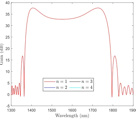
Figure.3shows the graph of the initial bandwidth generated by the first segment of the PCF of length 30-m. The parameters used
for simulation for the first segment of the amplifier are as used by Cao et al. [1]. The highest peak gain on this bandwidth is
37.66-dB while the lowest gain on the bandwidth is 32.77-37.66-dB, which gives a gain ripple of ±4.89 𝑑𝐵. This difference in gain along the
gain bandwidth spectrum means signals are not uniformly amplified along the FOPA. The gain bandwidth generated by the first segment of the FOPA is measured to be 280-nm.
Fig. 3. Gain spectrum generated by the first PCF segment, 30-m (k = 0).
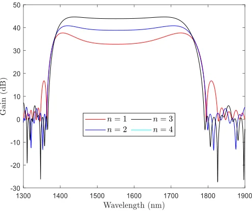
In Figure.4, the highest gain attained on the gain bandwidth spectrum is 40.78-dB and the lowest gain measured is 39.03-dB
Fig. 4. Gain spectrum generated by two PCF segment, 35 and 21-m.
Adding another PCF segment results in further reduction in the gain ripple as observed in Figure.5 the maximum gain measured
on this gain bandwidth is 44.62-dB, while the lowest is 43.90-dB, resulting in a gain ripple of ±0.72𝑑𝐵. The introduction of the
third segment of PCF results in reduction in gain ripple by ±4.17 𝑑𝐵.
Fig. 5. Gain spectrum generated by three PCF segments: 30, 21 and 17-m.
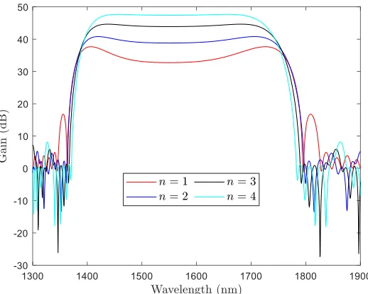
In Figure. 6, the fourth segment of the FOPA has a maximum gain point at 47.65-dB and the lowest gain point at 47.52-dB,
Fig. 6. Gain spectrum generated by four PCF segments: 30, 21, 17 and 14.4m.
Having investigated the effect of each segment on the amplifier performance, a few parameters were also simulated to see their effect on the performance of the PCF/n-PCF arrangement. The first analysis was how the FOPA gain properties are affected by length, pump power, pump power spacing and nonlinear properties of the PCF. A reference simulation of this FOPA was done using the parameters depicted in Table 1, with Figure 6 showing the simulation results.
The dispersion slope for n-PCF used in the simulation is −0.02772 𝑝𝑠 𝑛𝑚−2𝑘𝑚−1. The pump powers are both kept at
350mW, the lengths of the n-PCF remain the same and the
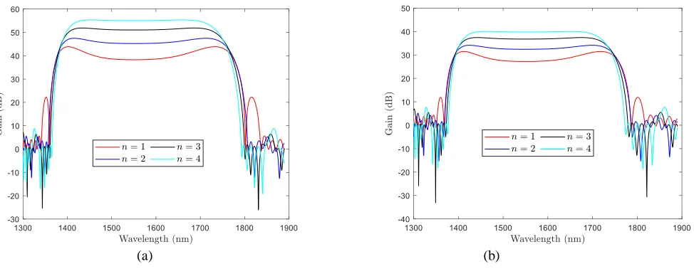
wavelengths of Pump 1 and Pump 2 are kept at 1548 nm and 1552 nm respectively. Considering, Figure. 7, the gain bandwidth of the FOPA gets flatter as the number of fibre segments increases but is hardly affected by the varying of the PCF segment lengths. The peak gain increased with increase in each off the segment’s length, each fibre segment was increased by 5-m and the results were captured in Figure. 7a. The maximum gain achieved was 66.1-dB. While a decrease of 5-m for each of the segment lengths resulted in a decrease in gain, to approximately 40-dB as shown in Figure. 7b. Thus, the length of the segments had an effect on the gain performance of the amplifier.
(a) (b)
and Pump 2 where both set to 0.25-mW and the gain was measured at 39.97-dB and a gain bandwidth of 232-nm.
(a) (b)
Fig. 8. Dual-pump FOPA gain spectrum with a) pumps power at 0.4-mW b) pump powers at 0.3-mW.
The analysis of the effect of nonlinear parameter, 𝛾 was done as shown in Figure. 9. The parameter was investigated for 125.7 𝑊−1𝑘𝑚−1 and 100.7 𝑊−1𝑘𝑚−1 respectively. It is evident from Figure.9a and Figure.9b that the higher the non-linear
parameter the higher the gain and the broader the gain spectrum and the lower the nonlinear parameter implies reduced gain and
gain spectrum respectively. The gain for the 125.7 𝑊−1𝑘𝑚−1 is 48.88-dB and the gain bandwidth is 237-nm while the gain for
the 100.7 𝑊−1𝑘𝑚−1 is 37.98-dB.
(a)
(b)
Fig. 9. Dual-pump FOPA gain spectrum for non-linear coefficient of; a) 125.7 𝑊−1𝑘𝑚−1
b) 100.7 𝑊−1𝑘𝑚−1.
Finally, in Figure.10, an investigation was made on the impact of the pump spacing (𝜆𝑝2− 𝜆𝑝1) two spacings were investigate
and compared to the spacing used in Figure.6. It is seen that as the spacing between the pumps increases so does the gain and gain
bandwidth. The gain for the 100-nm spacing is 47.64-nm and the corresponding gain bandwidth is 238-nm as shown in Figure.10a.
(a) (b)
Fig. 10. Dual-pump FOPA gain spectrum due to a) 100-nm pump spacing b) 20-nm pump spacing.
Much research has been done on FOPAs with HNLF segments cascaded together with dispersion compensating fibers (DCF). The HNLF segments generate the gain and smooth the gain bandwidth. while the DCF segments compensate the dispersion after each HNLF [8,11]. The resulting bandwidth from this theory is low while requiring high pump powers and longer lengths to produce the gain [6]. In some cases, Erbium Doped Fiber Amplifiers (EDFA) are used to boost the pump power which in turn introduces the negative gain dynamics that are associated with EDFAs. In using longer lengths, the loss becomes an issue requiring consideration. The DCF’s used have negative dispersion slopes but to achieve this low dispersion slope the core of the DCFs should be doped with fairly high
GeO2. Doping increases, the total fiber loss hence the cascading
of HNLF and DCF suffers from cumulative fiber losses due to the DCF doping and the lengths of the HNLF. In this paper we theoretically investigated the cascading of two PCF fibers with differing dispersion coefficients the model was developed in MATLAB. In recent years, techniques to fabricate and
manufacture PCFs with higher nonlinear coefficient, negative dispersion slope and low loss have been developed making this model a future possibility.
A theoretical model cascading two different PCFs with different parameters is modelled. The advantage of this theoretical model to those observed in [6, 8,11] is that higher gain and wider gain bandwidth is achieved with lesser pump power and reduced fiber length which in turn leads to reduced total amplifier losses. The gain ripple is nearly zero as we get to the fourth PCF segment allowing for uniform amplification of the signal across the whole bandwidth. The reduction of the pump power means the amplifier cost are reduced making their application in telecommunications much wider and acceptable. The major challenge for this model is how to practically join the two PCFs, research is still lagging in this area but some revolutionary techniques like pressure-assisted fusion splicing have been researched on and more research still needs to be done in this area.
Table II
Comparison of results in literature and this work.
Type of FOPA Gain (dB)
Gain spectrum
(nm)
Length of fiber (m)
Number of segments
Number of pumps
Pump power
Type of fiber
Ripple (dB)
Multi-section [15] 49 500 3 1 31.8dBm HNLF
Multi-section [4] 20.3 346nm 27.93 2 2 2W HNLF 0.2
Multi-section [2] 11.8 100 nm 422 4 1 500mW HNLF 0.3
Multi-section [8] 17.46 180 40 3 1 7W HNLF 0.82
Multi-section [9] 21.54 405 100 3 2 2W PCF 3
A theoretical model cascading two different PCFs with different parameters is modelled. The advantage of this theoretical model to those observed in Table 1, is that higher gain and wider gain bandwidth is achieved with lesser pump power and relatively reduced fiber length which in turn leads to reduced total amplifier losses due to reduce fiber losses. The gain ripple is greatly reduced as we get to the fourth PCF segment allowing for uniform amplification of the signal across the whole bandwidth. The reduction of the pump power means the amplifier cost are reduced making their application in telecommunications much wider and acceptable.
4. CONCLUSION
A theoretical analysis of a dual-pump FOPA based on two photonic crystal fibers with differing dispersion slopes has been theoretically implemented. Four segments were used, with the first segment used to generate the widest bandwidth possible and the subsequent segments smoothed the bandwidth, the segments where interspaced with shorter segments of n-PCF for dispersion compensation. It was shown that the length, pump power, non-linear parameter, and pump spacing have an effect on the overall gain as well as the FOPA bandwidth. An upward increase in any of the parameters resulted in an increase of the gain and the bandwidth. While a reduction in any of the parameters beyond the values of those used to generate Figure 6 led to a relative reduction in gain and bandwidth. The maximum achievable gain was 38-dB and the gain bandwidth were 280-nm for the reference design parameters of Table 1.
ACKNOWLEDGMENT
This work is funded by the Pan African University scholarship.
AUTHOR CONTRIBUTIONS
Kumbirayi proposed the idea and derived the mathematical model, Kibet wrote the MATLAB program, Hillary compiled the manuscript and supervised the project.
CONFLICTS OF INTEREST The authors declare no conflict of interest.
REFERENCES
[1] Cao, N.; Zhu, H.; Li, P.; Taccheo, S.; Zhu, Y.; Gao, X.; Wang, Z.
Flat and ultra-broadband two-pump fiber optical parametric amplifiers based on photonic crystal fibers. opt Rev 25, 2018, Volume 25, 316–322.
[2] Provino, L.; Mussot, A.; Lantz, E.; Sylvestre, T.; Maillotte, H. Broadband and flat parametric amplifiers with a multi-section dispersion-tailored nonlinear fiber arrangement. J. Opt. Soc. Am. 2003, Volume 20, pp. 1532-1537.
[3] S.Radic and C. J McKinstrie. “Two-pump fiber parametric
amplifiers”. Optical Fiber Technology, Volume 9, Issue 1, 2003, pp 7-23.
[4] Gao, M.; Jiang, C.; Hu, W.; Wang, J. Optimized design of two-pump
fiber optical parametric amplifier with two-section nonlinear fibers using genetic algorithm. Opt. Express 12, 2004, Volume 20, pp. 5603-5613.
[5] Zhang, W.; Wang, C.; Shu, J.; Jiang, C.; Hu, W. Design of
fiber-optical parametric amplifiers by genetic algorithm. IEEE Photonics technology letters, 2004, Volume 16, pp. 1652-1654.
[6] Wong, K.K.Y.; Shimizu, K.; Uesaka, K.; Kalogerakis, G.; Marhic,
M.E.; Kazovsky, L.G. Continuous-wave fiber optical parametric
amplifier with 60 dB gain using a novel two-segment design. CLEO '03, 2003, Volume 15, pp. 1707-1709.
[7] Pakarzadeh, H.; Taghizadeh, M.; Hatami, M. Designing a photonic
crystal fiber for an ultra-broadband parametric amplification in telecommunication. Journal of nonlinear optical physics & materials, 2016, Volume 25. 2, pp. 1-13.
[8] Gao, J.; Cao, Y.; Chen, F.; Sun, B.; Hu, Z. Theoretical and
simulation analysis of the fiber optical parametric amplifier (FOPA) with cascaded structure. Photonics optoelectronics meetings (POEM). 2012, volume 8333, pp. 1-8.
[9] Gao, M.; Jiang, C.; Hu, W. Dual-pump broadband fiber optical
parametric amplifier with three section photonic crystal fiber scheme. SPIE 5623, Passive components and fiber-based devices, 2005, Volume 5623, pp. 300-307.
[10] Marhic, M.E. Scalar OPA theory. In fiber optical parametric
amplifiers oscillators and related devices.; Cambridge university press.; Cambridge, United Kingdom, 2008; pp. 31-52.
[11] Marhic, M.E.; Yang, F.S.; Ho M.C.; Kazovsky, L.G.
High-nonlinearity fiber optical parametric amplifier with periodic dispersion compensation. Journal of light wave technology, 1999, Volume. 17, pp. 210-215.
[12] Li, Y.; Qian, L.; Lu, D.; Fan, D. Ultrafast four-wave mixing in single-pumped fiber optical parametric amplifiers. J. Opt. A Pure Appl. Opt. 8, 2006, Volume 8, pp. 689–694.
[13] Marhic, M.E.; Andrekson, P.A.; Petropoulos, P.; Radic, S.;
Peucheret, C.; Jazayerifar, M. Fiber optical parametric amplifiers in optical communication systems, Laser Photonics rev. 9, 2015, Volume 3, pp. 50–74.
[14] Franco, M. A.R.; Ruggieri, M.T.; Serrão, V. A.; Sircilli, F.; Abe, N.
M. Photonic crystal fiber for chromatic dispersion compensation, RIAO/OPTILAS, 2004, Volume 5622, pp.955-960.
[15] J. Hansryd and P. A. Andrekson, “Broad-band
continuous-wave-pumped fiber optical parametric amplifier with 49-dB gain and wavelength-conversion efficiency,” IEEE Photonics Technology Letters, vol. 13, no. 3, pp. 194–196, 2001.