Author for correspondence:
1Asst.Professor ECE Dept,Holy Mary Institute of Technology, Hydrabath
E-VOTING THROUGH BIOMETRIC SECURITY SYSTEM WITH MMS USING ARM
PROCESSOR
Y.B.T.Sundari, J.Pushpa Rani
ABSTRACT
This paper presents a new technique to evaluate e-voting system with highly security optimization method; this is based on biometric security system such as face recognition along with finger prints. This system, introduced a device which is highly security using a software platform and hardware platform. The entire system controlled by ARM processor which is used in hardware section. In voting, time the maintenance is also an important factor. This system is developed in such a way that it can work for specific period, which has been implemented with the help of a software platform. The image and finger print of voter or authorized person are stored in database of system. Voter image will be captured by the camera and fingerprint will be taken by the fingerprint reader. These two are compared with the database of the system. This method processed by MATLAB GUI with PCA algorithm. The system doesn’t allow unauthorized person and it is indicated by Blinking of the Red LED. It can allow the only authorized person and it is indicated by Blinking of the Green LED. So malfunctions can be avoided by using this system. The LCD display which is connected to the processor will display the polling information. This system also sends the voter information along with image through MMS to the administrator of the election commission. Instead of sending voted information from every polling booth to the election commission, the data can be aggregated and can be compressed at a point, where different data from different polling booths can be mingled. This can be done wirelessly by forming wireless network where the data can be aggregated and compressed at the network main node and can be sent to election commission main office. Because sometimes the polling booths have to be established at remote places where no proper facilities are available to place wired connections, like mountain areas and very rural areas. This will bring quick results in election.
Keywords: ARM processor; MATLAB GUI; MMS; PCA; LED; LCD display;
INTRODUCTION
Electronic voting (also known as e-voting) is a term encompassing several different types of voting, embracing both electronic means of casting a vote and electronic means of counting votes. Electronic voting technology can include punch cards, optical scan voting systems and specialized voting kiosks (including self-contained Direct-recording electronic (DRE) voting systems)[1] [3]. It can also involve transmission of ballots and votes via telephones, private computer networks, or the Internet. Electronic voting systems may offer advantages compared to other voting techniques [2]. An electronic voting system can be involved in any one of a number of steps in the setup, distributing, voting, collecting, and counting of ballots, and thus may or may not introduce advantages into any of these steps. The main aim of this project is to develop a Electronic Voting Machine with maximum security facilities.
Figure1. Block diagram of E-Voting machine
DESIGN AND IMPLEMENTATION
The block diagram of the proposed E-Voting machine is illustrated in Figure 1. The Proposed system uses an ARM processor as a core [1]. To the Processor all the modules are interfaced. A camera is interfaced with the PC and in that the voter’s image will be saved .So, at the time of voting image comparison will be done on the PC using a face detection image processing technique [4]. After this security Bio-Metric authentication will be carried out through the finger Print sensor. So every voter has to come across the two security level. This will bring a high security among the voting system than the existing one.
After this two level security system, the e-voting machine will be activated. That means, the key pad will come to an active mode [6] [7]. This mode can be understood with the help of indicators. In this process, the key pressing is applicable for one time. Because once the key is pressed the system will go to its default state. It is nothing but the key pad will go to deactivate state. So one voter will be having one chance to poll. To which Party the voter has polled will be displayed on the display system. So the display system of this machine is designed for the purpose of giving an acknowledgement and it will provide a confirmation to the voter. The core Processor will count the vote and it will be stored in the processor memory. This count can be send to the election commission department through the communication module. For this MMS module communication used in mobile communication .This module will be interface to the processor using the UART communication which uses an RS-232 cable for interfacing.
OVERVIEW OF THE E-VOTING SYSTEM
In this E-Voting machine, ARM LPC2148 is acting as a core Processor [1] [2] [4]. This will be having all the controlling instructions in it. Once the face and finger recognition is matched then the controlling commands will be given to the keypad to make it active and Processor get ready to read the button press. If the voter presses any button then the corresponding party name will be displayed on the Display system and the count will be stored in the processor also. A MMS module is connected to the processor through RS-232 communication. Thus according to admin instruction the polled vote count along with image of the voter will be sent to the concerned person.System Hardware:
ARM PROCESSOR
The ARM7 family includes the ARM7TDMI, ARM7TDMI-S, ARM720T, and ARM7EJ-S processors. The ARM7TDMI core is the industry’s most widely used 32-bit embedded RISC microprocessor solution. Optimized for cost and power-sensitive applications, the ARM7TDMI solution provides the low power consumption, small size, and high performance needed in portable, embedded applications.
The ARM7TDMI-S core is the synthesizable version of the ARM7TDMI core, available in both VERILOG and VHDL, ready for compilation into processes supported by in-house or commercially available synthesis libraries.
processor core.
FINGER PRINT SENSOR
Fingerprint recognition refers to the automated method of verifying a match between two human fingerprints.
Fingerprints are one of many forms of biometrics used to identify an individual and verify their identity. The analysis of fingerprints for matching purposes generally
PATTERNS
The three basic patterns of fingerprint ridges are the arch, loop, and whorl.
ARCH PATTERN
An arch is a pattern where the ridges enter from one side of the finger, rise in the center forming an arc, and then exit the other side of the finger. The image of an arch pattern is displayed in the following.
LOOP PATTERN
The loop is a pattern where the ridges enter from one side of a finger, form a curve, and tend to exit from the same side they enter.
WHORL PATTERN
In the whorl pattern, ridges form circularly around a central point on the finger.
MINUTIA FEATURES
The major Minutia features of fingerprint ridges are: ridge ending, bifurcation, and short ridge.
RIGHT ENDING
BIFURCATION
Bifurcations are points at which a single ridge splits into two ridges.
SHORT RIDGE
Short ridges (or dots) are ridges which are significantly shorter than the average ridge length on the fingerprint.
WIRELESS COMMUNICATION
MMSMultimedia messaging service (MMS) is emerging as a natural but revolutionary successor to short messaging. MMS allows personalized multimedia messages containing content such as image. Multimedia messaging service does not mandate any maximum size for a multimedia message. Using the model, closed-form expressions for major performance parameters such as message loss, message delay and expiry probability have been derived.
THE MAIN CONTRIBUTIONS OF THE PRESENT; 1. Description of MMS and comparison with SMTP. 2. A simple approach to compute message delay which
enables the derivation of closed-form
3. Expressions for both virtual and actual message delay, and.
4. A simulation study of the system sensitivity to different parameters such as load, message.
MMS is very similar to SMS as it provides automatic and fast delivery of multimedia messages (MMs) between capable phones and other devices. MMS supports richer content types such as text, graphics, music, video clips.
COMMUNICATION
Using serial communication technique to make a communication between PC and Processor. The rate of data transfer in serial data communication is stated in bps (bits per second). Another widely used terminology for bps is baud rate. However, the baud and bps rates are not necessarily equal. This is due to the fact that baud rate is the modem terminology and is defined as the number of signal changes per second. In modems, there are occasions when a single change of signal transfers several bits of data. As far as the conductor wire is concerned, the baud rate and bps are the same.
In RS232, a 1 is represented by -3 to -25V, while a 0 bit is +3 to +25V, making -3 to +3 undefined. For this reason, to connect any RS232 to a microcontroller system we must use voltage converters such as MAX232 to convert the TTL logic levels to the RS232 voltage level, and vice versa. MAX232 IC chips are commonly referred to as line drivers.
cycle frequency of 921.6 kHz by 32 once more before timer 1 to set the baud rate uses it. Therefore, 921.6 kHz divided by 32 gives 28,800 Hz. Using this interface we are communicating between the PC and the Processor.
FIRST SECURITY LEVEL: FACE OR
IMAGE RECOGNITION WITH RESULT
Image recognition is composed of two parts: classification and validation. The classification can be done somewhat easily by statistics of dimensions and pattern features of each type of image. On the other hand, validation is very difficult because we cannot obtain counterfeits that might appear in future, while we can collect plenty of genuine images. Moreover, statistics for a two-class (genuine and counterfeit bank notes) problem
When the image processing technique is started the following window will be displayed on the screen. So the voter can get ready for the face recognition process.
.
Figure1: Face recognition window
In this system a monitoring section displays whether the finger print and face recognition have been matched or
not. This output will be displayed on the monitoring screen using visual basic software.
After face recognition, the finger print recognition process will be started. For high security again one
password will be given to each and every voter to access his own data base.
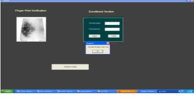
SECOND SECURITY LEVEL: FINGER PRINT RECOGNITION WITH RESULT
Figure 3. Adding database samples of Finger prints
Now, user has to submit the username and password. So that his data base will be opened by the software and it will ask the finger print of the voter. Then,
the given finger print will be compared with the stored database. If it is matched then the signal will be send to the processor.
Figure 4. Re-vote verification process
In this process, if a voter tries to vote once again then the system will detect that and it will neglect that polling and a warning message will be displayed on the screen
Figure 4: Recognition Process
Figure 5: Time verification Process
BEFORE VOTING TIME THE LCD DISPLAY
Figure6:16*2 LCD display
The LCD display will show the voter information and it can show the voting or not.
AFTER VOTING THE LCD DISPLAY
Figure7: After voting the LCD display shows the with party vote
UNAUTHORIZED PERSON
Figure8: For Unauthorized person the red LED will be blinked.
AUTHORIZED PERSON
RECEIVING MMS
Figure10: The voter image through the mms will be sent to Election commissioner
FLOW CHART OF ENTIRE SYSTEM
validating section has finger print sensor, camera and computer.
The camera will capture the image of the voter and it will compares with the database and its result will be given to the PC after the image processing technique and the finger print sensor gets the finger print of the voters and sends to the PC. In PC the finger print image is compared with existing image. If the image is matched, the computer sends the command to the processor, which in turns displays it to the voter through the indicators.
anyone try to poll their vote beyond the time limit, then a warning will be given to the voter through the outputs screen and also the processor reject that vote. Then finally the counted vote will be send to the authorized person. This system also sends the voter information along with image through MMS to the administrator of the election commission or authorized person. This will bring quick results in election. Because of its speed, high security, and time maintenance. This system will bring an effective change over the existing system.
REFERENCES
[1]. S. Brock, D. Jefferson, and R. Rivets, “A Modular Voting Architecture ("Frogs")”, Workshop on Trustworthy Elections WOTE '01, August 26-29, 2001, Marconi Conference Centre, 2001.
[2]. Council of Europe, “Legal, Operational And Technical Standards For E-voting”, Recommendation Red (2004)11 30th of September 2004, Council of Europe Publishing, 2004.
[3]. Federal Election Commission, “Voting System Standards. Volume: Performance Standards”, U.S. Federal Election Commission, 2002.
[4]. D. Grizzlies, “Secure Electronic Voting - New trends, new threats....”, 7th Computer Security Incidents Response Teams Workshop Syros, Greece, September 2002.
[5]. M. Bishop, and D. Wagner, “Risks of e-voting”, Communications of the ACM, Volume 50, Issue 11. COLUMN: Inside risks. ACM, 2007, p. 120.
[6]. D. Dill, B. Schneider, and B. Simons, “Voting and Technology: Who Gets to Count Your Vote?“, [7]. Communications of the ACM August 2003/Vol. 46, No. 8.ACM, 2003, pp. 29-31.
[8]. Open Rights Group, “May 2007 Election Report - Findings of the Open Rights Group Election Observation Mission in Scotland and England“, 20 June 2007.