e-ISSN: 2250-3021, p-ISSN: 2278-8719 Vol. 3, Issue 10 (October. 2013), ||V4|| PP 49-58
Transient Analysis of Three Phase Induction Machine With
Unbalanced Supply
K.S.Sandhu, A.V.J.S.Praneeth, A.V.S.S.S.Pradeep
(Electrical Engineering Department,National Institute Of Technology,Kurukshetra) (Electrical Engineering Department,National Institute Of Technology,Kurukshetra )(Acharya Nagarjuna University College Of Engineering And Technology,Guntur )
Abstract: - In this paper transient model of three phase induction motor using d-q axis theory in stationary reference frame, is proposed to estimate the transient behaviour of the motor. Simulation results as obtained on a test machine are compared with the experimental results and the Closeness between the two shows the accuracy of the model as proposed. Further model is used to investigate the transient behaviour of three phase induction motor, with two phase supply system, without and after including the effects of phase angle control. The effect of Source Impedance on induction machine under unbalanced and balanced supply with the variations in the %DOU(Degree of unbalance) are analysed with THDs on all phases.
Keywords: - Induction motor, Modelling, Transient analysis, MAT LAB, Reference frames.
NORMENCLATURE:
Te - Electromagnetic torque. d, q - Direct and quadrature axes.
𝑅𝑠 - Stator Resistance. 𝑅𝑟 - Rotor Resistance. 𝐿𝑠 - Stator Self Inductances. 𝐿𝑟 - Rotor Self Inductance. 𝐿𝑀 - Mutual Inductance.
t - Time.
J - Moment of inertia v, i, λ - Voltage, current, and flux.
Vds,Vqs - d-axis and q-axis components of the stator voltage vector Vs Vdr,Vqr - d-axis and q-axis components of the rotor voltage vector Vr
I. INTRODUCTION
It is well known that with suitable assumptions, the dynamics of a Induction Machine (IM) can be well described with the help of transient model using any one of the reference frames[1-2]. Models are found to be capable to investigate the behaviour of machine under sudden disturbances. One of the researcher [11] also attempted to include the saturation effect during transient analysis. Many researchers [3-5] tried to investigate such predictions either using q axis modelling or MAT LAB simulation models. However, it was found that d-q axis model is very effective to predict the transient performance of any rotating electrical machine. The operation of induction motor under unbalanced supply operations and with specific faults on stator and rotor side is discussed in[6-10]. When the supplied three-phase voltage is unbalanced, the start up transients, dynamic performance, and steady-state characteristics of a three-phase induction motor using EMTP models is described in[13] and its analysis equations are taken from[14-16]. Looking the importance of dq axis models, in this paper an attempt has been made to use the d-q axis model for the investigation of a three phase induction motor, when operated with two phase supply system. A control algorithm is proposed to improve the performance under such operating conditions. The effect of source impedance on the balanced and unbalanced supply of induction machine has been analyzed with varying of degree of unbalance(%DOU).
DOU% =negative sequence component
positive sequence component * 100%
II. MODELING OF INDUCTION MOTOR
Following stator and rotor voltage equations may be used to model the three phase induction motor using stationary reference frame.
𝑉𝑑𝑠 = 𝑟𝑠𝑖𝑑𝑠+ 𝜌𝜆𝑑𝑠
𝑉𝑜𝑠 = 𝑟𝑠𝑖𝑜𝑠+ 𝜌𝜆𝑜𝑠 (1) 𝑉𝑞𝑟 = 𝑟𝑟𝑖𝑞𝑟− 𝜔𝑟𝜆𝑑𝑟+ 𝜌𝜆𝑞𝑟
𝑉𝑑𝑟 = 𝑟𝑟𝑖𝑑𝑟 + 𝜔𝑟𝜆𝑞𝑟+ 𝜌𝜆𝑑𝑟
𝑉𝑜𝑟 = 𝑟𝑠𝑖𝑜𝑟 + 𝜌𝜆𝑜𝑟 (2)
The advantage of this method is virtual flux measurement can be done using flux linkage equations which are given below
𝜆𝑞𝑠= 𝐿𝑙𝑠𝑖𝑞𝑠+ 𝐿𝑀 𝑖𝑞𝑠+ 𝑖𝑞𝑟 𝜆𝑑𝑠= 𝐿𝑙𝑠𝑖𝑑𝑠+ 𝐿𝑀 𝑖𝑑𝑠+ 𝑖𝑑𝑟
𝜆𝑜𝑠 = 𝐿𝑙𝑠𝑖𝑜𝑠
𝜆𝑞𝑟 = 𝐿𝑙𝑟𝑖𝑞𝑟+ 𝐿𝑀 𝑖𝑞𝑠+ 𝑖𝑞𝑟
𝜆𝑑𝑟 = 𝐿𝑙𝑟𝑖𝑑𝑟 + 𝐿𝑀 𝑖𝑑𝑠+ 𝑖𝑑𝑟
𝜆𝑜𝑟 = 𝐿𝑙𝑟𝑖𝑜𝑟 (3)
Solution of above equations along with torque equation as given below result in the complete solution of the machine
𝑇𝑒 = 3 2 ∗
𝑃
2 ∗ 𝐿𝑀∗ (𝑖𝑞𝑠𝑖𝑑𝑟− 𝑖𝑑𝑠𝑖𝑞𝑟) (4) 𝜔𝑚𝑒𝑐 ℎ = 𝜔𝑚𝑒𝑐 ℎ0+ ℎ ∗ (𝑇𝑒− 𝑇𝑗)/𝐽 (5)
𝜔𝑟 = 𝑃
2 ∗ 𝜔𝑚𝑒𝑐 ℎ (6)
For three phase induction motor operation with two phase supply, voltage and flux equations may be modified as:
𝑉𝑞𝑠= 𝑟𝑠𝑖𝑞𝑠+ 𝜌𝜆𝑞𝑠
𝑉𝑑𝑠 = 𝑟𝑠𝑖𝑑𝑠+ 𝜌𝜆𝑑𝑠 (7) 𝑉𝑞𝑟 = 𝑟𝑟𝑖𝑞𝑟− 𝜔𝑟𝜆𝑑𝑟 + 𝜌𝜆𝑞𝑟
𝑉𝑑𝑟 = 𝑟𝑟𝑖𝑑𝑟+ 𝜔𝑟𝜆𝑞𝑟+ 𝜌𝜆𝑑𝑟 (8) 𝜆𝑞𝑠 = 𝐿𝑙𝑠𝑖𝑞𝑠+ 𝐿𝑀 𝑖𝑞𝑠+ 𝑖𝑞𝑟 𝜆𝑑𝑠 = 𝐿𝑙𝑠𝑖𝑑𝑠+ 𝐿𝑀 𝑖𝑑𝑠+ 𝑖𝑑𝑟
𝜆𝑞𝑟 = 𝐿𝑙𝑟𝑖𝑞𝑟+ 𝐿𝑀 𝑖𝑞𝑠+ 𝑖𝑞𝑟
𝜆𝑑𝑟 = 𝐿𝑙𝑟𝑖𝑑𝑟 + 𝐿𝑀 𝑖𝑑𝑠+ 𝑖𝑑𝑟 (9)
Fig 1. Shows the flow chart of such modelling
III. RESULTS AND DISCUSSIONS
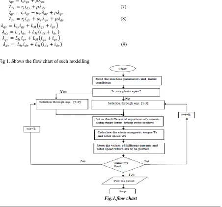
Fig.2.shows the experimental set up of slip ring induction machine[Appendix- 1].
Fig.2. Experimental setup
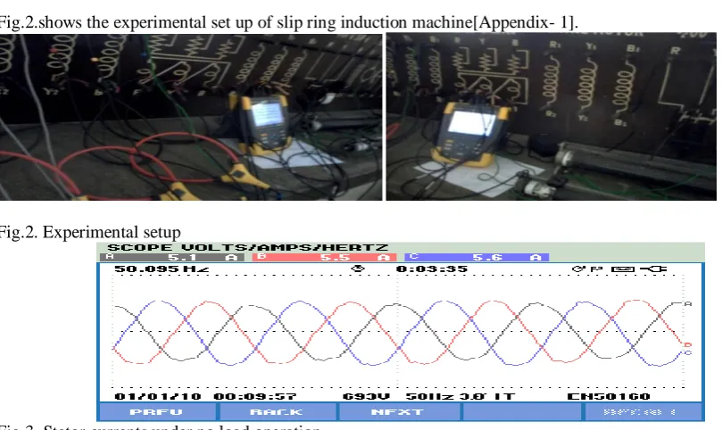
Fig 3. Stator currents under no load operation.
Fig.3 shows the experimental results of stator currents under no load and Fig.4 shows the simulated results on the same test machine. Ia as per simulated results under steady state condition(point A,Fig5) is 5.1A(7.202/ 2).
Fig.4 Stator phase a current under no load(simulated)
Table 1. gives the comparisions of simulated and experimental data on test machine loaded and unloaded conditions. Comperision of experimental and simulated results shows good agreement or proves the validity of the transient model.
Table1. comparision of experimental and
simulated result of current
Fig.5 to Fig.7 shows the simulated results for the currents and torque slip characteristics of the machine with one phase open. As observed the operation results into excessive phase currents and oscillating torque. Here a new control scheme (as shown in Fig.8) is proposed to improve the performance under such operation. Phase control technique is proposed to control the phase angle between line phases using voltage sensors, torque sensor and control unit. Implementation of such scheme results into the improved transient performance as shown in Fig 9 to Fig.24.
S.NO
Phase current
% error Experimental Simulated
1 5.1 5.098 0.039
2 5.3 5.287 0.245
3 5.7 5.717 -0.298
4 6 6.053 -0.883
5 6.9 6.863 0.5362
6 7.4 7.384 0.2162
Analysis of simulation results as shown above gives:
In the absence of phase angle control(i.e. when phase angle is 1200 )it results into:
Maximum value of inrush current in contrast to other phase angles and it is so irrespective of load. Steady state currents of the phase A under the loaded conditions exceeds its rated value.
Steady state torque developed is maximum at 1200 irrespective of load at machine shaft, however it is
oscillating in nature,not desirable.
Settling time in case of torque and speed variations comes to be highest under all operating conditions. b. With the phase angle control scheme after adjusting the phase angle as 900, it is observed that:
Inrush current is minimum.
None of the currents exceeds the rated value even under high load conditions. For any load, speed build up is found to be smooth.
Steady state torques appear to be minimum as compared to other cases,however it is free from oscillations. c. As phase angle increases from 900 to 1200 , it results in to:
An increase in inrush current and its steady state value may exceed the rated one under heavy load condition.
Speed build up does not remains smooth.
Settling time to reach the steady state of currents,speed,torque also increases.
The machine in normal operation with balanced supply and without source impedance:
S.NO Load
applied (Tl-N-m)
THDs of Currents after instant load applied(t=5sec)
THDs of Voltages after load applied(t=5 sec)
A B C A B C
1 0 0.05 0.12 0.11 0.13 0.09 0.07
2 5 0.33 0.71 0.7 0.13 0.09 0.07
3 10 0.71 1.53 1.50 0.13 0.09 0.07
4 15 1.08 2.35 2.31 0.13 0.09 0.07
5 20 1.45 3.17 3.11 0.13 0.09 0.07
6 25 1.82 3.99 3.92 0.13 0.09 0.07
7 30 2.18 4.81 4.73 0.13 0.09 0.07
The machine in normal operation with balanced supply and with source impedance:
S.NO Load
applied (Tl-N-m)
THDs of Currents after instant load applied(t=5sec)
THDs of Voltages after load applied(t=5 sec)
A B C A B C
1 0 0.13 0.31 0.27 0.33 0.2 0.2
2 5 0.52 1.15 1.06 0.33 0.2 0.2
3 10 0.90 2.00 1.85 0.33 0.2 0.2
4 15 1.28 2.85 2.64 0.33 0.2 0.2
5 20 1.66 3.70 3.43 0.33 0.2 0.2
6 25 2.03 4.55 4.22 0.33 0.2 0.2
7 30 2.40 5.40 5.00 0.33 0.2 0.2
8 34 2.69 6.07 5.63 0.33 0.2 0.2
Load applied
0 10 20 30 40
% T HDs of Currents A ,B ,C 0 1 2 3 4 5 6 7
Load applied vs THD of A(without source impedance) Load applied vs THD of A(with source impedance) Load applied vs THD of B(without source impedance) Load applied vs THD of B(with source impedance) Load applied vs THD of C(without source impedance) Load applied vs THD of C(with source impedance)
Load applied
0 10 20 30 40
% T HDs of v olt ages of A ,B ,C 0.05 0.10 0.15 0.20 0.25 0.30 0.35
Load applied vs THD of A (without source impedance) Load applied vs THD of A (with source impedance) Load applied vs THD of B (without source impedance) Load applied vs THD of B (with source impedance) Load applied vs THD of C (without source impedance) Load applied vs THD of C (with source impedance)
Fig:25 Load applied vs THDs of currents A,B,C Fig:26 Load applied vs THDs of voltages A,B,C
Analysis of the above observations gives:
The THDs of the voltages is same (constant) under balanced operation of the machine when different loads are applied after some time (t=5sec) with and without source impedance.
The THDs of currents are increasing with different loads applied on machine at balanced operation with and without source impedance.
The THDs of voltage increases when the machine operated from without source impedance to with source impedance.
The THDs of currents increases when the machine operated from without source impedance to with source impedance at particular loads.
The machine in normal operation with unbalanced supply and without source impedance:(larger time ( total wave)) load of 10 N-M applied.
S.N O
Degree of unbalance (DOU%)
THDs of Currents THDs of Voltages
A B C A B C
1 2.985 19.90 1.85 23.67 0.77 0.48 0.45
2 4.545 20.50 3.45 22.95 0.66 0.42 0.38
3 5.020 20.35 3.29 23.15 0.39 0.25 0.23
4 6.153 19.94 2.66 23.84 0.51 0.31 0.31
5 7.812 20.09 3.31 23.77 0.1 0.06 0.07
6 11.29 20.01 3.95 23.95 0.02 0.02 0.01
The machine in normal operation with unbalanced supply and with source impedance:(larger time ( total wave)) load of 10 N-M applied.
S.NO Degree of
unbalance (DOU%)
THDs of Currents THDs of Voltages
A B C A B C
1 2.985 20.00 1.71 24.10 0.97 0.39 0.68
2 4.545 20.54 3.20 23.48 0.35 0.39 0.31
3 5.020 20.35 2.91 23.79 0.10 0.14 0.29
4 6.153 20.10 2.61 24.25 0.60 0.19 0.51
5 7.812 20.32 3.38 24.14 0.10 0.12 0.30
6 11.29 20.05 3.63 24.60 0.35 0.08 0.41
7 15.00 19.59 3.57 25.20 0.96 0.47 0.76
The machine in normal operation with unbalanced supply and without source impedance:(small time (after load applied)) load of 10 N-M applied after 5 sec.
S.NO Degree of
unbalance (DOU%)
THDs of Currents THDs of Voltages
A B C A B C
1 2.985 3.33 1.82 1.69 0.76 0.46 0.46
2 4.545 8.21 2.63 2.99 0.66 0.42 0.38
3 5.020 1.71 0.56 0.73 0.39 0.24 0.23
4 6.153 0.89 1.28 1.19 0.51 0.32 0.29
5 7.812 0.59 0.82 0.83 0.1 0.07 0.06
6 11.29 0.35 0.57 0.61 0.01 0.01 0.01
7 15.00 0.25 1.03 0.79 0.63 0.38 0.37
The machine in normal operation with unbalanced supply and with source impedance:(small time (after load applied)) load of 10 N-M applied after 5 sec.
S.NO Degree of
unbalance (DOU%)
THDs of Currents THDs of Voltages
A B C A B C
1 2.985 3.18 1.68 1.54 0.60 0.37 0.36
2 4.545 2.04 0.31 0.58 0.7 0.46 0.39
3 5.020 1.57 0.64 0.78 0.3 0.19 0.17
4 6.153 0.88 1.03 1.02 0.25 0.15 0.14
5 7.812 0.71 0.47 0.63 0.28 0.18 0.16
6 11.29 0.33 0.58 0.63 0.2 0.01 0.01
7 15.00 0.28 1.07 0.80 0.67 0.41 0.40
TOTAL WAVE: TOTAL WAVE VOLTAGE:
DOU%(DEGREE OF UNBALANCE)
2 4 6 8 10 12 14 16
TH Ds of cur rents A ,B ,C 0 5 10 15 20 25 30
DOU vs THD A( without source impedance) DOU vs THD A( with source impedance) DOU vs THD B( without source impedance) DOU vs THD B( with source impedance) DOU vs THD C( without source impedance) DOU vs THD C( with source impedance)
%DOU(DEGREE OF UNBALANCE)
2 4 6 8 10 12 14 16
TH D s of Vol tage A, B,C 0.0 0.2 0.4 0.6 0.8 1.0 1.2
Fig:27 %DOU vs THDs of currents A,B,C Fig:28 %DOU vs THDs of voltages A,B,C
SMALL PORTION(load applied after t=5 sec) :
% DOU
2 4 6 8 10 12 14 16
TH Ds of Cur rent A ,B ,C( A ft er l oad applied) 0 2 4 6 8 10
%DOU vs THD of A (without source impedance) %DOU vs THD of A (with source impedance) %DOU vs THD of B (without source impedance) %DOU vs THD of B (with source impedance) %DOU vs THD of C (without source impedance) %DOU vs THD of C (with source impedance)
% DOU
2 4 6 8 10 12 14 16
TH D s of Vol tage A, B,C 0.0 0.2 0.4 0.6 0.8
% DOU vs THD of A(without source impedance) % DOU vs THD of A(withsource impedance) % DOU vs THD of B(without source impedance) % DOU vs THD of B(with source impedance) % DOU vs THD of C(without source impedance) % DOU vs THD of C(with source impedance)
Fig:29 %DOU vs THDs of currents A,B,C Fig:30 %DOU vs THDs of voltages A,B,C
Analysis of the above observations gives:
The THDs of the currents increases with the increases in % DOU of the induction machine with and without the effect of source impedance in phases A and C and the THDs decreases in B.
The THDs of the currents with load applied at starting decreases when compared with load applied after some time.
The THDs of the voltages increases with the increases in % DOU of the induction machine with and without the effect of source impedance in phases A and C and the THDs decreases in B.
IV. CONCLUSION
In this paper d-q axis based transient modelling of induction machine is used to analyse the behaviour of a there phase Induction motor. As observed simulated results as obtained under balanced supply operation are found to be in good agreement with the experimental results on a test machine. From simulation results, it is observed that an open circuits across one phase causes excessive currents and distortion even under no load conditions. Simulation with phase angle as 1200 results into undesirable operation of machine with excessive
inrush as well as steady state currents. In addition it results in to oscillating torque, highly undesirable. In order to improve the performance under such operations a control scheme is proposed to control the phase angle between the line phases. Implementation of this scheme shows the controlled behaviour of machine in terms of its inrush current, speed build up or torque oscillations. The effect of the unbalanced operation of the induction machine will effects the THDs in the machine to a higher value more than IEEE standards(>5%).So it is better to apply the load after some time rather than instant operation with load for the harmonic free operation along with the source impedance in the stator part of the induction machine.
REFERENCES
[1]. I. Boldea, S.A. Nasar. “The Induction Machine Handbook”, CRC Press, 2002.
[2]. Chee-mun ong “Dynamic Simulation of Electric Machinery” 1998 by prentice Hall press USA.
[3]. Vivek Pahwa and K. S. Sandhu, “ Transient Analysis of Three-Phase Induction Machine Using Different Reference Frames”, ARPN Journal Of Engineering And Applied Sciences, Vol. 4, No. 8, OCT 2009. [4]. K. L . SHI, T . F. CHAN, Y. K. WONG and S. L . HO, “Modelling and Simulation of the Three-Phase
Induction Motor Using Simulink”, Int. J. Elect. Engg. Educ., Vol. 36,DEC-2002.
[5]. Sudhir Kumar, P. K. Ghosh and S. Mukherjee, “A Generalized Two Axes Modelling, Order Reduction and Numerical Analysis of Squirrel Cage Induction Machine for Stability Studies”, International Journal of Advanced Computer Science and Applications, Vol. 1, No. 5, pp: 63-68,November 2010.
[6]. Li Wang ,Lih-Shyh Liu, “Analysis of Unbalanced Voltages on start up Transients of a Three Phase Induction Motor using EMTP Models” vol.1.pp:308-312,2000 IEEE.
[8]. S.S. Murthy and G.J. Berg, Bhim Singh, C.S. Jha, B,P. Singh “Transient analysis of a Three Phase Induction Motor with Single Phase Supply” IEEE Transactions on Power Apparatus and Systems, Vol. PAS-102, No. 1, January 1983.
[9]. Rangarajan M. Tallam, Thomas G. Habetler and Ronald G. Harley” Transient Model for Induction Machines with Stator Winding Turn Faults” ,Vol.1.pp: 304-309, IEEE Transactions,2000.
[10]. Hongzhong Ma“Analysis of Starting Performance of Induction Machine under Rotor Winding Faults” IEEE.Trans. on Industry Applications, voI.35,. pp.1000-1006, Sep/Oct 2006.
[11]. Nuh Erdooan, Humberto Henao,Richard Grisel , “The Analysis of Saturation Effects on Transient Behaviour ofInduction Machine Direct Starting”Vol.2.pp:975-979 ,2004 IEEE.
[12]. P.C.Krause, Oleg Wasynczuk, Scott D.Sudhoff,” Analysis of electrical Machines And Drive Systems”, IEEE series John willey student edition, pg. No. 140-251.
[13]. Williams, “Operation of three-phase induction motors on unbalanced voltages,” AIEE Trans Power Apparatus and Systems, vol. 73, 1954, pp 125-133.
[14]. P.C. Krause, Analysis of Electric Machinery, New York McGraw-Gill,Book Company, 1987.
[15]. Tarek AROUI, Yassine KOUBAA and Ahmed TOUMI , “ Magnetic Coupled Circuits Modelling of Induction Machines Oriented to Diagnostics”, Leonardo Journal of Sciences, Issue 13, July-December 2008, p. 103-121.
[16]. Sushma.P, Rajalakshmi, Samaga.B.L Vittal.K.P, Member,“DQ Modelling Of Induction Motor For Virtual Flux Measurement”, IPEC 2010, ©2010 IEEE.
[17]. B. K. Bose. 2007. Power Electronics and AC Drives. Pearson Prantice Hall. [18]. R. Krishnan. 2007. Electric Motor Drives. Pearson Prantice Hall.
APPENDIX:
Nominal Voltage 400/231 V
Power 7KW
Current 14.7/25.4 A
Speed 1450 RPM
Frequency 50 HZ
Resistance(𝑅𝑆) 1.1 Ohm
Resistance(Rr) 1.52 Ohm
Leakage Inductance (Ls,Lr) 0.00876 Ohm
Mutual Inductance(M) 0.07096 Ohm
Moment Of Inertia (J) 0.36 Kg𝑚2
Coefficient Of Friction(B) 0.006 Nm/rad/Sec
Source Impedance(Xs) 0.108 Ohm
Dr. Kanwarjit Singh Sandhu was born on December 21, 1957. He received the B.Sc.Eng. (Electrical), M.Sc. (Electrical), and Ph.D. (Electrical Machines) degrees from Regional Engineering College, Kurukshetra University, Kurukshetra, India, in 1981, 1985, and 2001, respectively. He joined the Electrical Engineering Department of Regional Engineering College, Kurukshetra, as a Lecturer in January 1983. Currently, he is Professor in the Electrical Engineering Department, National Institute of Technology, Kurukshetra. He has more than 130 international & national publications in the area of electrical machines & drives/ induction generators/wind energy conversion/ power quality/ artificial intelligence/ power system.
A.V.Jaya Sai Praneeth was born on November 6, 1988. He received the B.TECH degree from P V P Siddhartha Institute of Technology, Andhra Pradesh, India in 2010. Currently he is pursuing his M.TECH in Power Electronics & Drives(PED) from NIT Kurukshetra. His field of intrest includes power electronics, electrical machine modelling and drives.