Localization and Mapping of Flying Robot in
GPS-Denied Environments
Ms. K. A Drishya Ms. Divya K .S
PG Student(M. Tech) PG Student(M. Tech)
Department of Applied Electronics and Communication Department of Applied Electronics and Communication Thejus Engineering College. Kerala. Thrissur Thejus Engineering College. Kerala. Thrissur
Mr. Sakthiprasad. K .M Ms. Anjaly Krishnan
PG Student(M. Tech) Assistant Professor
Department of Applied Electronics and Communication Department of Electronics and Communication Thejus Engineering College. Kerala. Thrissur Thejus Engineering College. Kerala. Thrissur
Abstract
Generally the search and rescue missions in the case of monitoring operations, natural and man-made disasters mainly rely on manned aerial vehicles. But these methods were highly risky for human pilot or rescuers because these included high navigation precision and long operation times, These unmanned aerial vehicles were used only in GPS prone areas based on an inbuilt map. These drawbacks are overcome in this proposed paper by designing a controlled hexacopter which provides vision-controlled flying in GPS-denied environments. It consists of two stages: The onboard stage runs the visual odometry algorithm and the off-board stage runs the localization & mapping algorithm.
Keywords: Mapping, vision-controlled, odometry, Localization, Hexacopter
________________________________________________________________________________________________________
I.
I
NTRODUCTIONThe improvements in technology have led to the use of UAVs (unmanned aerial vehicles) over the last few decades. UAVs were used in several fields and replaced human pilots. UAVs offer promises of speed and access to regions that are inaccessible to ground robotic vehicles. They can be scaled down to small sizes and can operate in closed and confined environments. In search and rescue operations there are few constraints like time is critical and if there is any delay then it may result in human losses. The environmental conditions are also unfriendly that are difficult for the rescuers to easily reach. So by using UAVs a critical support is provided for search and rescue operations. UAVs are fast and can perform operations that are hard to be executed by human operators at low operating costs. UAVs can be deployed in an area of interest and report their collected information to a remote ground station or rescue team. This paper describes the technical challenges and the results achieved from hardware design and embedded programming to vision-based navigation and mapping, with an overview of how all the modules work [1].
II.
R
ELATED WORKS(IJSTE/ Volume 1 / Issue 10 / 059)
technologies possessed few drawbacks. The UGVs can be either wired or wireless. If they are wired then there is chance that it may get struck and suppose it is wireless then it is difficult to track their location ones they wander away from the operators site And in the case of UAVs they are mainly used in the GPS prone areas and are confined only to a specific location based on its inbuilt map. This paper is organised as follows, Section II consists of related works regarding the UAVs. Section III describes the proposed approach. Experimental results are shown in Section IV and Section V concludes the paper.
III.
P
ROPOSED APPROACHIn this proposed work, a vision-controlled flying robot is designed for search and rescue operations in GPS-denied environments using ARM 11.Localization & mapping is provided with visual odometry and sonar data(data from ultrasonic sensor). This robot can fly by using an onboard camera and inertial measurement unit. These sensors do not require any external infrastructure so they can easily operate in unknown environments where GPS signals are low. These sensors provide a system that is capable for vision-aided navigation and mapping.
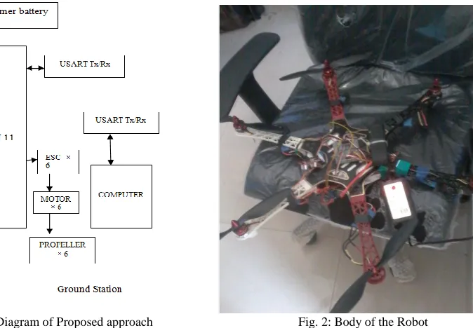
Block Diagram: A.
The block diagram shows the components used in this approach. The two main modules used here are local navigation module and global navigation module. Local navigation module represents the body of the robot and global navigation module is the ground station.
Fig. l: Block Diagram of Proposed approach Fig. 2: Body of the Robot
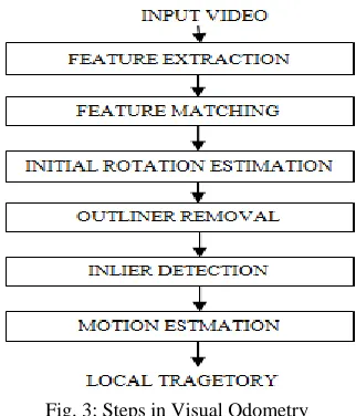
Visual Odometry: B.
Fig. 3: Steps in Visual Odometry
Visual odometry is the method of estimating the motion of an agent based on the input obtained from a camera attached to it. Motion can be obtained based on the variation in the poses of the images captured from camera. Its similar to wheel odometry where motion is determined based on the turns in the wheels [9],[10].Steps in Visual odometry are:
1) Feature extraction: There are two methods to find feature points :a) Find features in one image and track them in another using correlation. This is used for nearby viewpoints. b) To independently detect the features in all the images and match them based on similarity metrics. This is used for far by viewpoints. The relative motion can be computed using appearance or feature based method. Appearance based method use the intensity information of all the pixels in the two input images. Feature based methods only use salient features extracted across the images.VO implements feature based approach.During feature detection image is searched for some key point’s . Corners and blobs are few features that have to be detected. Corner is point of intersection of two edges and blob is pattern that differs in intensity and colours. Features are extracted using FAST feature detector where threshold is set in such a way that it extracts all features.
2) Feature matching: Each feature is assigned a descriptor of intensity values 9x9 pixels .Feature matching includes comparing all feature descriptors in two images. Features are matched using mutual consistency where by using hamming distance the sum of absolute difference is calculated. If the absolute difference is a small value then it is a perfect match.
3) Initial rotation estimation: Here minimizing of the sum of squared pixel error is done between the down sampled version of current and previous frames [8],[9].
4) Outliner removal: Matched points are contaminated by outliners which are wrong data associates. The causes of outliners are image noise, occlusions, blur .etc. For camera motion to be estimated accurately outliners has to be removed. This is the task of Random Sample Consensus (RANSAC)[11].This method performs model based hypothesis on a set of data points and compares it with other data points. The hypothesis that gives highest consensus is the solution.
5) Inlier Detection: Inlier points to the hypothesis are computed by point to equipolar line distance. But better than this method is the directional error method. This method measures the angle between a ray of image feature and equipolar plane
[10].Finally the motion is computed after comparing a new image with reference image.
Localization & Mapping: C.
Determining the robots position when limited sensor information is available is a key challenge in robotics. Generally the robots position is determined using GPS or beacons. But these methods include expensive hardware cost and processing power. So in this paper localization & map construction can be done using camera and ultrasonic sensor data. Here there is no prior knowledge of environment and map is autonomously constructed by the robot. There are two algorithms [12]:
(IJSTE/ Volume 1 / Issue 10 / 059)
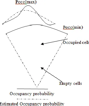
Occupancy algorithm: This algorithm creates a map of the environment by integrating data collected over time. As the robot explores the environment, data from the sweeps is combined with information about the robots location to update the occupancy values for grid map. The probability of occupancy is given by Bayes rule. The occupancy value ranges from 0 to 1 and 0.5 if the cell is undecided or unexplored. Based on thresholds it can be determined if the cell is occupied, empty or unexplored [12].The energy radiated by the sensor is in the form of a cone which has half beam-width angle of 12.5 degrees. In figure 3, it is shown that the probability that a cell is occupied along the arc is Pocc(max) and it drops exponentially to Pocc(min). But there are sometimes chances of occurrence of error. Dead reckoning algorithm is used to make the previous readings zero inorder to prevent any errors.
Fig. 4: Mapping using camera and sonar data
IV.
E
XPERIMENTAL RESULTSThe program is simulated in MATLAB .With the help of Zigbee the information is transmitted from body of robot to base station and vice versa A 180-degree sweep is represented by red arrow .If there is any obstacle it is shown in red colour. The number of humans that are present in an unknown location is viewed using Terminal software.
Fig. 5: Output viewed in matlab Fig. 6: Life detection viewed in Terminal software
V.
C
ONCLUSIONThis paper proposes the design of a flying robot that implements localization and mapping in GPS-denied environments. Visual odometry algorithm runs onboard and localization and mapping algorithm runs off-board. By using PIR sensors lives are detected in unknown locations.
R
EFERENCES[2] Carlos Marques, Jo„oCristÛv„oIdMind-Engenharia de Sistemas, Lda, PÛloTecnolÛgico de Lisboa, Lote1, Estrada do PaÁo do Lumia,Pedro Lima, Jo„oFraz„o, Isabel Ribeiro, Rodrigo Ventura Institute for Systems and Robotics Instituto Superior TÈcnico, Av. RoviscoPais,‖ RAPOSA: Semi-Autonomous Robot for Rescue Operations
[3] Pierre-Jean Bristeau, François Callou, David Vissière, Nicolas Petit,‖The Navigation and Control technology inside the AR.Drone micro UAV‖,International Federation of Automatic Control (IFAC).
[4] Jakob Engel, Jurgen Sturm, Daniel Cremers, ‖Accurate Figure Flying with Quadrocopter Using Onboard Visual and Inertial Sensing‖. [5] Sunantha Krishnan and Anthony SelvaJessobalan,‖Rescue robot‖, International Journal of innovations in Engineering and technology. [6] Trupti B. Bhondve1, Prof.R.Satyanarayan2 , Prof. MoreshMukhedkar,‖ Mobile Rescue Robot for Human Body Detection in Rescue Operation of
Disaster, in International Journal of Advanced Research in Electrical, Electronics and Instrumentation Engineering.
[7] Mohammad RehanRasheed, Ibrahim Mohammad Hussain,‖Cost Effective Spy Ball Robot for Surveillance, Rescue and Exploration‖, TRANSACTIONS on ELECTRONICS &COMMUNICATIONS.
[8] D. Scaramuzza and F. Fraundorfer, ―Visual odometry: Part I—The first 30 years and fundamentals,‖ IEEE Robot. Automat.Mag., vol. 18, no. 4, pp.80–92, 2011
[9] F. Fraundorfer and D. Scaramuzza, ―Visual odometry: Part II—Matching, robustness, and applications,‖ IEEE Robot. Automat.Mag., vol. 19, no. 2, pp. 78–90, 2012.
[10] Markus Achtelika, Abraham Bachrachb, RuijieHeb, Samuel Prenticeband Nicholas Royb,‖Stereo Vision and Laser Odometry for Autonomous Helicopters in GPS-denied Indoor Environments
[11] Javier Civera, Oscar G. Grasa, J. M. M. Montiel, Andrew J. Davison,‖ 1-Point RANSAC for EKF Filtering. Application to Real-Time Structure from Motion and Visual Odometry‖.
[12] VassilisVarveropoulos,‖Robot Localization and Map Construction Using Sonar Data‖.
[13] A. Bachrach, R. He, and N. Roy, ―Autonomous flight in unstructured and unknown indoor environments,‖ in Proc. European Conf. Micro Air Vehicles,2009, pp. 1–8.