Author for correspondence:
M. Leela Ramesh
Volume-6 Issue-4
International Journal of Intellectual Advancements
and Research in Engineering Computations
Heat transfer augmentation by using twisted tapes as inserts for tube side
flow of liquids with convection
M. Leela Ramesh
1, V.Mahesh Kumar Reddy
2K.Anil Kumar
31
Asso Professor, Dept of Mech Engg, Holy Mary Institute of Technology and Science Telangana, India 2
Asst Professor, Dept of Mech Engg, Holy Mary Institute of Technology and Science Telangana. 3
Asst Professor, Dept of Mech Engg, Holy Mary Institute of Technology and Science Telangana.
ABSTRACT
This concept deals with the effect of twisted tape inserts as Passive Heat transfer augmentation device. Effect twisted tape (TT), on heat transfer and friction factor for heating of water for Reynolds number range 2500 -30000, was studied experimentally in a double pipe counter flow heat exchanger. One tape of different twist ratio (yw=3.69, yw=4.39, yw=5.25) for Twisted tape (TT), were used. Based on constant flow rate, the heat transfer coefficient was found to be 1.18-3.66, times the smooth tube values for Twisted tape (TT), respectively. The nusselt number values were found to be 3.23-5.96 times the smooth tube values for Twisted tape (TT), respectively. Based on constant pumping power, the heat transfer coefficient values were found to be 0.88 -1.62, times the smooth tube values for Twisted tape (TT), respectively. Based on the increase in Heat transfer coefficient, Performance evaluation criteria R1 & R3, it was concluded that twisted tape performs much better than the smooth tube.
Keywords:Heat transfer augmentation, Heat transfer, Twisted tape.
INTRODUCTION
Twisted-Tape Flow and Heat Transfer
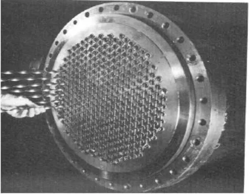
It is well known that energy transport is considerably improved if the flow is stirred and mixed well. This has been the primary principle in the expansion of enhancement techniques that generate swirl flows. Among the technique that promote secondary flows, twisted-tape inserts are perhaps the most convenient and effective (Manglik and Bergles, 2002).They are relatively easy to manufacture and fit in the tubes of shell-and-tube or tube-fin type heat exchangers. A typical usage in the multi-tube bundle of a shell-and-tube heat exchanger.
The geometrical features of a twisted tape, as depicted in Fig. 1.2, are described by its 180º twist pitch H, the thickness δ, and the width w. In most
usage, where snug-to-tight-fitting tapes are used, w
≅ d, and the severity of the tape twist is characterized by the dimensionless ratio y = (H / d).
The helical twisting nature of the tape, besides providing the fluid a longer flow path or a greater residence time, imposes a helical force on the bulk flow that promotes the generation of secondar y circulation. The consequent well-mixed helical swirl flow significantly enhances the convective heat transfer (Manglik and Bergles, 2002, 1993a, 1993b).
considered by designers to optimize their thermal-hydraulic performance. ratio y = (H / d).
The helical distortion nature of the tape, besides providing the fluid a longer flow path or a greater residence time, imposes a helical force on the bulk flow that promotes the generation of secondary circulation. The consequent well-mixed helical swirl flow significantly enhances the convective heat transfer (Manglik and Bergles, 2002, 1993a,
1993b). In most cases, depending on how tightly the tape fits at the tube wall and what material it is made of, there may be some tape-fin effects as well. The enhanced heat transfer due to twisted-tape inserts, is also accompanied by an increase in weight drop and suitable trade-offs must be considered by designers to optimize their thermal-hydraulic performance.
Fig.1.1: Shell-and-tube heat exchanges with twisted-tape inserts
Fig. 1.2 Twisted-tape geometry
EXPERIMENTAL SETUP OF VCR
ENGINE
Specifications of heat exchanger used
The experimental study is done in a double pipe heat exchanger having the specifications as listed below:-
Specifications of Heat Exchanger: Inner pipe ID = 22mm
Inner pipe OD=25mm Outer pipe ID =53mm Outerpipe OD =61mm
Material of construction= Copper Heat transfer length= 2.43m
Pressure tapping to pressure tapping length = 2.825m
Water at room temperature was allowed to flow through the inner pipe while hot water (set point 60°C) flowed through the annulus side in the counter current direction.
Types of inserts used
For experimentation, three types of twisted tape inserts made from stainless steel strips of thickness 1.80 mm were used.
used in the inner pipe of ID 22mm as shown in Fig 5.1.
2. The insert used for the experiment were made of twisted stainless steel strip of thickness 1.80mm. The present work deals with finding the friction factor and the heat transfer coefficient for the various types of twisted tapes with twist ratios
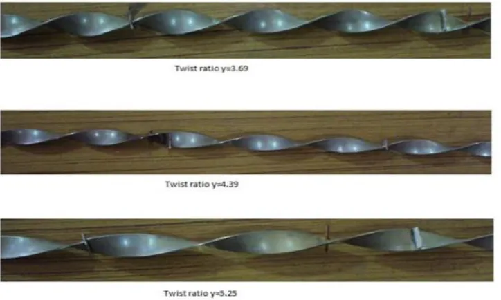
(yw=3.69, 4.39, 5.25) and comparing those results with that of smooth tube and to finish finding the heat transfer development in comparison to a smooth tube on constant flow rate basis (R1) as well as constant pumping power basis (R3).
Fig 2.1: Reduced Width Twisted Tape (RWTT)
Fabrication of twisted tapes
The stainless steel strip of length 125cm, width 16mm and thickness 1.80mm were taken. Holes were drilled at both ends of every tape so that the two ends could be fixed to the metallic clamps. Desired twist was obtained using a Lathe machine. One end was kept fixed on the tool post of the lathe while the other end was given a slow rotatory motion by rotating the chuck side. During the whole operation the tape was kept under tension by applying a mild pressure on the tool post side to avoid its distortion. Three tapes with varying twist ratios were fabricated (yw=5.25, yw =4.39, yw =3.69) as shown in fig 3.1. The end portions of the fabricated tapes were cut and holes of 3mm size were drilled for joining the two tapes. Three tapes with the same twist ratio and twist in the same direction were joined by using small screws with nuts, thus giving a total length of 3.0m, which is sufficient enough for the double pipe heat exchanger, used for the experiment.
Since the tape width is less than inside diameter of inner tube, so holes of 2.5mm size were drilled into the tape & cycle spokes of length 20mm were welded into the tape at an interval of 40cm. This allows the tape to be concentric with the tube.
Experimental setup
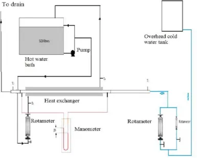
Fig 2.1 shows the schematic diagram of the experimental setup. It is a double pipe heat exchanger consisting of a calming section, test section, rotameters, overhead water tank for supplying cold water & a constant temperature bath (500 litre capacity) for supplying hot water with in-built heater, pump & the control system. The test section is a smooth copper tube with dimensions of 2430mm length, Inner tube-22mm ID, and 25mm OD; Outer GI pipe-53mm ID, and 61 mm OD. The
outer pipe is well
insulated maltreatment 15mm military
with the flow ranges 1 to 5 LPM and 300 to 1250 LPH, are used to measure the flow of cold water. The water, at temperature is drawn from Associate in Nursing overhead tank maltreatment gravity flow. Similarly a rotameter is provided to regulate the flow of predicament from
the water predicament tank. ot water flow rate is kept constant at 1000LPH. Two pressure tapings- One simply before the check section and also the different simply when the check section ar conn ected to the U-tube pressure gage for pressure drop mensuration.
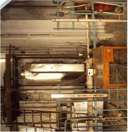
Fig 2.3 Photograph of the experimental setup
Experimental procedure
All the rotameters & RTD are calibrated first
1. For rotameter standardization calibration, water is collected in a bucket. Weight of water collected & time of collection is noted to calculate mass flow rate of water.
2. .A minimum of 3 readings are taken for each flow rate & average flow rate is used for calculations. The readings are given in A.1.1 & A.1.2
3. For RTD calibration, all the RTDs are dipped in a constant water bath & readings shown by each RTD are noted. Temperature shown by one of the RTD (T1)
was taken as reference & corrections were made to other RTDs values (i.e. T2-T4) accordingly.
Twist Ratio(y) of the twisted tapes were calculated.
Twist Ratio, yw = H/W
Where H = Linear distance of the tape for 180° rotation W = thickness of twisted tape
Standardization of the set-up
results for the smooth tube & comparing them with the standard equations available.
4 For friction issue determination: Pressure drop is measured for every flow with the assistance of pressure gage at temperature. a. The U-tube pressure gage used per
chloromethane because the manometric liquid. b. A little of bromine crystals were added to it to
impart a colour to the CCl4.
c. Air bubbles ar far from the pressure gage in order that the liquid levels in each the limbs were equal once the flow is stopped.
d. Water at room temperature is allowed to flow through the inner pipe of the heat exchanger. e. The manometer reading is noted.
For heat transfer coefficient calculation:
a. Then, heater is put on to heat the water to 60°C in a constant temperature water tank of capacity
500 litres. The tank is provided with a centrifugal pump & a bypass valve for recirculation of hot water to the tank & to the experimental setup.
b) Predicament at concerning 60°C is allowed to labor under the annulus facet of warmth money dealer at 1000LPH (mh=0.2715 Kg/sec).
c) Cold water is now allowed to pass through the tube side of heat exchanger in counter current direction at a desired flow rate.
d) The water inlet and outlet temperatures for both hot water & cold water (T1-T4) are recorded only after temperature of both the fluids attains a constant value.
e) The procedure was perennial for various cold water flow rates starting from zero.0331-0.3492 Kg/sec.
Preparation of Wilson chart
Rd + (2.1)
Where Rd is the dirt resistance
All the resistances, except the primary term on the RHS of equation (1), are constant for this set of experiments.
For Re>10000, Seider Tate equation for smooth tube is of the form: hi=A ×Re
0.8
Therefore Eq. (2.1) can be written as
(2.2)
K is to be found from the Wilson chart (1/Ui vs. 1/Re0.8) as the intercept on the y-axis.
Fig: 2.4 Wilson chart
7. After confirmation of validity of experimental values of friction factor & heat transfer coefficient in smooth tube with standard equations, friction factor & heat transfer studies
with inserts were conducted.
Standard equations used
I. Friction factor (f0) calculations
a. For Re< 2100
(2.3)
b. For Re>2100
Colburn’s Equation:
(2.4)
II. Heat transfer calculations
i. Laminar Flow:
For Re<2100
Nu= f(Gz)
Where Gz= (2.5)
a. For Gz<100, Hausen Equation is used.
( ) 0.14 (2.6)
b. For Gz>100, Seider Tate equation is used.
(2.7)
ii. Transition Zone:
For 2100<Re<10000, Hausen equation is used
(2.8)
iii. Turbulent Zone:
For Re>10000, Seider-Tate equation is used.
(2.9)
Viscosity correction Factor is assumed to be equal to 1 for all
RESULTS AND DISCUSSION
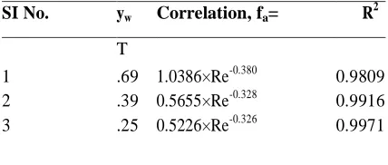
Table 1 gives correlations for variation of friction factor with Reynolds number for different twisted tapes along with the correlation coefficient, R2 based on regression analysis.
As we can see form the correlations it is quite clear that friction factor is increasing with decrease in twist ratio..
As the R2value is very close to 1, so we can easily make out that the correspondence holds true for respective twisted tapes in the given range of Reynolds Number.
Table 1 Correlations for Friction Factor for different twisted tapes SI No. yw Correlation, fa= R2
T
1 .69 1.0386×Re-0.380 0.9809 2 .39 0.5655×Re-0.328 0.9916 3 .25 0.5226×Re-0.326 0.9971
The range of Performance evaluation criteria R1 (based on constant mass flow rate) & R3 (based on
constant pumping power), & fa/fo for different tapes used is given below:
SINo. Y Range of R1 Range of R3 Range of fa/fo
TT
1 3.69 1.50-3.66 1.07-1.66 3.70-5.96
2 4.39 1.43-3.35 1.04-1.62 3.43-4.43
3 5.25 1.18-2.75 0.88-1.42 3.23-4.18
CONCLUSION
For same twist ratio, twisted tape shows higher heat transfer coefficient & friction factor increase because of higher degree of turbulence created. On the basis of performance evaluation criteria R1 & R3, we can say that Baffled reduced width twisted tape shows better performance than smooth tube. Baffled reduced width twisted tape gives higher heat transfer coefficient than the smooth tube. The
correlations derived from friction issue values have R2 (Correlation coefficient) values terribly on the brink of one. So, the correlations are often used for locating friction issue values for several styles within the given vary of Sir Joshua Reynolds range. With decrease in twist magnitude relation, heat transfer coefficient increases but at the same time pressure drop also increases
REFERENCES
[1]. B.Adrian and K. Allan D. Heat transfer enhancement. In Heat Transfer Handbook, 14, 2003, 1033, -1101, Wiley-interscience.
[2]. Bergles, A.E. ―Techniques to augment heat transfer. In Handbook of Heat Transfer Applications (Ed.W.M. Rosenhow), 3, 1985 (McGraw-Hill, New York).
[3]. Bergles, A.E. and Blumenkrantz, A.R. ―Performance evaluation criteria for enhanced heat transfer surfaces . Proc. Of 5th Int. Heat Conf., Tokyo, 2, 1974, 239-243.
2001, 341-352.
[5]. Megerlin et al., 1974. F.E. Megerlin, R.W. Murphy and A.E. Bergles, ―Augmentation of heat transfer in tubes by use of mesh and brush inserts . J. Heat Transfer, 1974, 145– 151
[6]. A. Dewan, P. Mahanta, K Sumithraju, P. Suresh kumar ―Review of passive heat transfer augmentation techniques . Proc. Institution of Mechanical Engineers 218, 2004. Part A: Journal of Power and Energy. [7]. Whitham, J. M. The effects of retarders in fire tubes of steam boilers. Street Railway. 12(6), 1896, 374.
[8]. Saha, S. K. and Dutta, A. ―Thermo-hydraulic study of laminar swirl flow through a circular tube fitted with twisted tapes. Trans. ASME, J. Heat Transfer, 123, 2001, 417–421.
[9]. Date, A. W. and Singham, J. R. Numerical prediction of friction and heat transfer characteristics of fully developed laminar flow in tubes containing twisted tapes. Trans. ASME, J. Heat Transfer, 17, 1972, 72. [10]. Hong, S. W. and Bergles, A. E. Augmentation of laminar flow heat transfer in tubes by means of twisted-tape
inserts.Trans. ASME J. Heat Transfer, 98, 1976, 251–256.
[11]. Tariq, A., Kant, K. and Panigrahi, P. K. Heat transfer enhancement using an internally threaded tube. In Proceedings of 4th ISHMT–ASME Heat and Mass Transfer Conference, India, 2000, 277–281 (Tata McGraw-Hill, New Delhi).
[12]. Manglik, R. M. and Bergles, A. E. ―Heat transfer and pressure drop correlations for twisted tape insert in isothermal tubes. Part 1: laminar flows. Trans. ASME, J. Heat Transfer, 116, 1993, 881–889.
[13]. Saha, S. K., Dutta, A. and Dhal, S. K. Friction and heat transfer characteristics of laminar swirl flow through a circular tube fitted with regularly spaced twisted-tape elements. Int.J. Heat and Mass Transfer, 44, 2001, 4211– 4223
[14]. Lokanath, M. S. and Misal, R. D. An experimental study on the performance of plate heat exchanger and an augmented shell and tube heat exchanger for different types of fluids for marine applications. In Proceedings of 5th ISHMT– ASME Heat and Mass Transfer Conference, India, 2002, pp. 863–868 (Tata McGraw-Hill, New Delhi).
[15]. Lokanath, M. S. ―Performance evaluation of full length and half length twisted tape inserts on laminar flow heat transfer in tubes. In Proceedings of 3rd ISHMT–ASME Heat and Mass Transfer Conference, India, 9, 1997, 324 (Tata McGraw-Hill, New Delhi).
[16]. Al-Fahed, S., Chamra, L. M. and Chakroun, W. Pressure drop and heat transfer comparison for both micro-fin tube and twisted-tape inserts in laminar flow. Experimental Thermal and Fluid Sci., 18, 1999, 323–333. [17]. Q. Liao, M.D. Xin ―Augmentation of convective heat transfer inside tubes with three-dimensional internal
extended surfaces and twisted-tape inserts’ Chemical Engineering Journal 78, 2000.
[18]. Ujhidy et. al, Fluid flow in tubes with helical elements, Chemical Engineering and Processing 42, 2003, 1–7. [19]. Suresh Kumar, P., Mahanta, P. and Dewan, A. Study of laminar flow in a large diameter annulus with twisted
tape inserts. In Proceedings of 2nd International Conference on Heat Transfer, Fluid Mechanics, and Thermodynamics, Victoria Falls, Zambia, 2003, KP3.