60
Original Article
Symmetry Two-axis Tilt Angle Capacitive Sensor System
Tran Thi Thuy Ha
1, Nguyen Dac Hai
2, Bui Thanh Tung
3,*1Posts and Telecommunications Institute of Technology Hanoi, Km10, Nguyen Trai, Hanoi, Vietnam
2Hanoi University of Industry, 298 Cau Dien, Bac Tu Liem, Hanoi, Vietnam
3VNU University of Engineering and Technology, 144 Xuan Thuy, Cau Giay, Hanoi, Vietnam
Received 15 March 2019
Revised 29 March 2019; Accepted 29 March 2019
Abstract: This paper presents the design, fabrication and operation of a highly symmetrical two-axis capacitive sensor. The proposed sensor consists of five electrodes, including of an excitation electrode and two pairs of sensing electrodes with exactly the same dimensions, arranged at identified symmetrically locations on a 3D printed hollow sphere, which containing dielectric medium formed by the partly filled oil and the remaining air. The proposed sensor can measure the tilt angle about the x-axis and y-axis with symmetrical outputs. The proposed sensor is fabricated using a rapid prototyping technology and mounted on the surface of a printed circuit board (PCB) for mechanical packaging and signal processing. Experimental measurement results show that the sensor system can measure the tilt angle in both the x- and y-axis with sensitivity of 103 mV/degree and resolution of ±1 degree in the range of -30 degree to +30degree. This sensor system can be used in many military and consumer applications.
Keywords: Capacitive sensor, Fluidic sensor, Two-axis tilt angle sensor.
1. Introduction
Nowadays, there are many types of tilt angle sensors have been proposed and developed for widely used in industry, scientific research, medical support for patients and in several consumer applications. Some common applications that the tilt sensors are used including: robot balancing, support mobility activities for people with disabilities and people with a stroke or spinal cord injury [1-4]; patient monitoring device [5]; self-balancing scooter [6]; adjusting the rotation angle of the solar system [7]. A tilt angle sensor can be designed based on several working principles. Examples include solid-sphere
________
Corresponding author.
Email address: [email protected]
differential capacitive tilt sensor [8], optical tilt sensor [9], micro-channel based conductive liquid tilt sensor [10], liquid tilt sensor [11, 12], tilt sensor based on wavelength and light received at the output [13], capacitive sensor based on connected molding device technology [14].
In this paper, we propose a two-axis symmetry tilt sensor based on the two-phase liquid/air dielectric capacitive sensing to achieve similar properties on both sensing axes. The proposed senor structure is simple and can be fabricated using 3D printing technology. Therefore, this sensor is inexpensive and can be used for various applications in military as well as civilian.
2. Structure and simulation of the proposed tilt sensor
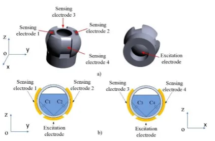
Figure 1. Proposed structure of the capacitive tilt angle sensor: (a) 3D image of the sensor; (b) The sensor capacitor pairs for sensing tilt angle about the x axis (C1, C2) and about the y axis (C3, C4).
The structure of the tilt sensor is shown in Figure 1. The two-phase liquid/air dielectric medium is contained in a hollow sphere with an internal diameter of 15 mm, equivalent to a volume of 1766 mm3.
Four thin rectangular electrodes in the same dimension are mounted on the outside of the sphere, forming two pairs of sensing electrodes (or collector electrodes). The electrodes of each pair are positioned symmetrically with the spherical center axis (see Fig. 1a). Fig. 1b shows the correctional views of the two-electrode pair configuration. The two planes are perpendicular which are formed the working plane of the proposed sensor, correspondence to the x- and y- axis (see Fig. 1b). At the bottom of the sphere, a rounded electrode is mounted. This electrode serves as the excitation electrode (or emitter electrode). When the sensor is tilted, capacitance formed by the two pair of sensing electrodes is changed. By monitoring the differential capacitance of these capacitor pairs the applied tilt angle can be estimated.
When the sensor is at 00 angle in x-axis and y-axis as shown in Fig. 2-a2 and Fig. 2-b2, respectively,
the dielectric fluid level covering the collector electrodes is the same. Hence, the capacitance values of the capacitors are equal, i e., C1 = C2 and C3 = C4. Therefore, the differential capacitance values of each
capacitor pair are zero: ΔCx = C1 - C2 = 0, ΔCy = C3 - C4 = 0. When the sensor is counterclockwise tilted
about the x-axis (Fig. 2-a3), the dielectric fluid level covers the electrode C1 is increased and the
electrode C2 is decreased. Consequently, the differential capacitance ΔCx = C1 - C2 is increased.
Conversely, when the sensor is clockwise tilted about the x-axis (Fig. 2-a1), the differential capacitance ΔCx = C1 - C2 is then decreased. When having tilt angle in x-axis, as the dielectric fluid covers the
capacitors C3 and C4 with the same level, although C3 and C4 are change but they change in the same
amount. As the result, the differential between C3 and C4, ΔCy, is keep unchanged. Similarly, on the y
(Fig. 2-b3) and ΔCy = C3 - C4 decreases when the sensor tilts clockwise (Fig. 2-b1) while keeping the
ΔCx unchanged. The changes of capacitor when the sensor is tilted are summarized in Table 1. By
monitoring the differential capacitance value of ΔC1 and ΔC2, the tilt angle of the sensor about the x
-axis and y-axis can be estimated, respectively.
a1 a2 a3 a)
C1
C2 C1C2
C3
C4 C3 C4 C3 C4
b1 b2 b3 b)
C1 C2
Z Z Z
Z
Z Z
yoz plane
xoz plane
Figure 2. Capacitance changes when the sensor is tilted about the x axis (a) and y axis (b).
Table 1. Capacitance change due to tilt angle
Tilt angle C1 C2 ΔCx
(C1 - C2) C3 C4
ΔCy
(C3 - C4)
X-axis Counterclockwise tilted ↑ ↓ ↑↑ # # 0
Clockwise tilted ↓ ↑ ↓↓ # # 0
Y-axis Counterclockwise tilted # # 0 ↑ ↓ ↑↑
Clockwise tilted # # 0 ↓ ↑ ↓↓
In this study, the differential measurement approach is proposed as the combination of the differential capacitor structure and differential capacitance measurement circuit. With this approach, the common noise will be suppressed, leading to the robustness of the sensor system.
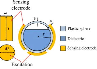
A model of the sensor was built and its performance was simulated by using Ansoft Maxwell software. Figure 3 shows the design and configuration of the electrodes in detains. The sensor consists of a round copper electrode on the bottom as the excitation electrode (emitter electrode) and four rectangular copper electrode which are symmetrically bonded surrounding the sphere structure. The oil as the dielectric fluid is partly filled inside the sphere to the desired level. Table 2 and 3 shows the dimensions of the model as well as parameters of the materials used in the simulations.
d2
C1 C2
Plastic sphere
k n
r
Dielectric
Sensing electrode
l w
Sensing electrode
Excitation electrode
Table 2. Parameters of tilt angle sensor
Parameter Value (mm)
Spherical inner radius (r) 7.5
Thickness of sphere shell (k) 0.2
Length of the sensing electrode (l) 10.0
Width of sensing electrodes (w) 5.0
Diameter of the excitation electrode (d2) 10.0
Thickness of electrode (n) 0.2
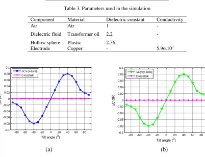
Table 3. Parameters used in the simulation
Component Material Dielectric constant Conductivity
Air Air 1 -
Dielectric fluid Transformer oil 2.2 -
Hollow sphere Plastic 2.36 -
Electrode Copper - 5.96.107
(a)
(b)
Figure 4. Differential capacitance of ΔC1 and ΔC2 changes when applying tilt angle from 00 to 1800
on (a) x-axis and (b) y-axis.
Simulation results are presented in Fig. 4. As can be seen, differential capacitance changes on the both axes output are the same, thanks to the symmetrical arrangement of the sensing electrodes. When the sensor is tilted from 0° to 30°, the capacitance change is linear versus the tilt angle.
3. Experimental results and discussions
The proposed sensors are fabricated using additive printing technology (STRATASYS Objet500 3D printer). This 3D printer allows printing very thin wall structures with high accuracy for fabricating the designed sensor. The oil is partly filled to the sensor, up to 40% volume of the sphere. Therefore, the two-phase dielectric medium is configured by 40% oil and 60% air. Five copper electrodes are cut by
-80 -60 -40 -20 0 20 40 60 80 -0.1
-0.08 -0.06 -0.04 -0.02 0 0.02 0.04 0.06 0.08 0.1
C
(
fF
)
Tilt angle (0)
Cx (x-axis) Crosstalk
-80 -60 -40 -20 0 20 40 60 80 -0.1
-0.08 -0.06 -0.04 -0.02 0 0.02 0.04 0.06 0.08 0.1
C
(
fF
)
Tilt angle (0) Cy (y-axis)
CNC and mounted on the outer side of the sphere to create two pairs of sensing capacitors. The parameters of the fabrication structure are given in Table 2.
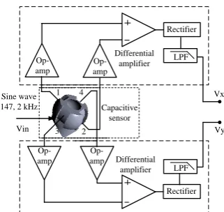
Figure 5 shows the measurement setup for evaluating the working of the proposed tilt sensor. The sensor structure is mounted on a PCB. The PCB is then fixed on a rotating disk with readout resolution of ±1°. For measuring small capacitors, the frequency applied to the excitation electrode is generally used between 100 kHz and 2 MHz. With available electrical components, a sinusoidal signal with a frequency of 147.2 kHz was implemented in this work. Signals from four sensing electrodes are fed into two differential amplifiers. The output of the differential amplifiers is then fed into the rectifiers and low-pass filters (LPF) to extract the sensing signal as shown in the diagram in Figure 6. The outputs of the sensor are Vx and Vy, respectively. For evaluating the performance of the sensor, first, the sensor
system is aligned on the rotating disk for applying tilt angle in x-axis. Then, the sensor system is rotated 90 degree on the sensing plane for applying tilt angle in y-axis. Vx and Vy are collected during the tilting
process and plotted.
Sensor
Rotating discs to measure tilt
angle
Figure 5. Measurement setup for evaluating the performance of the proposed tilt angle sensor.
Op-amp Op-amp Op-amp Op-amp 1 2 3 Rectifier Differential amplifier Differential amplifier Rectifier LPF LPF Vx Vy Capacitive sensor Sine wave
147, 2 kHz Vin
4
Figure 6. Block diagram of the proposed tilt sensor readout circuit.
(a) (b)
Figure 7. Output voltage versus applied tilt angle about the x-axis (a) and y-axis (b).
-80 -60 -40 -20 0 20 40 60 80 -3 -2 -1 0 1 2 3 O u tp u t V o lt a g e ( v o lt )
Tilt angle (0)
Vx (x-axis) Crosstalk
-80 -60 -40 -20 0 20 40 60 80 -3 -2 -1 0 1 2 3 O u tp u t V o lt a g e ( v o lt )
Tilt angle (0)
Figure 7 shows the measured output voltage of the proposed sensor versus applied tilt angle from 0° to 180° in the x-axis and y-axis. The measured data shows that the output signals are linear in the range of about -30° to +30°. It also shows that the output response of the x-axis and y-axis are almost the same, thanks to the high accuracy 3D printing and well electrodes assembling processes. The non-matching range, from about 150° to 180°, would come from the fact that the two-phase fluidic chamber is not well control on the top of sphere structure. There are mechanical distortions on the top of chamber due to bonding process after filling the oil into the hollow sphere.
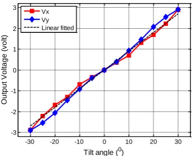
Figure 8 shows the relationship between the output voltage of the sensor versus applied tilt angle on the both x-axis and y-axis, in case the volume ratio of 40/60 oil/air. The measured results are linear in the range from about -30° to +30°. These measurement results are matching quite well with simulations. Within the linear range, the sensitivities are calculated to be 103 mV/° on both the axes. The linear range of the sensor is depended on the relative position of dielectric liquid and electrodes. The linear range can be extended by adjusting the electrode dimensions and the volume of the dielectric liquid. However, at that time, sensitivity of the sensor would be decreased. There is a tradeoff between the sensitivity and linear range. Detains in optimizing the sensor structure will be presented in another study.
Figure 8. Output voltage versus tilt angle about x-axis and y-axis. The measured results are linear in the range from about -30° to +30°.
The geometry parameters of the sensor were selected so that the sensor can fabricated easily using 3D printing technology and conventional method such as CNC. Although the working range of the sensor is limited experiment results proof the working principle of the proposed sensor system. In addition, from the results obtained we can confirm the validity of the simulation model built in this study and the model can be the design guidelines for optimizing the sensor performances such as working range and sensitivity in the future works.
4. Conclusions
This paper presents the design, fabrication and operation of a two-axis symmetrical capacitive sensor. The proposed sensor consists of five electrodes, includes of an exciting electrode and two pairs of sensing electrodes arranged at defined locations on a hollow sphere which partly filled of oil as the dielectric fluid. The proposed sensor can measure the tilt angle in x-axis and y-axis with symmetrical outputs. The sensor is fabricated using a rapid prototyping technology and packaged on the surface of a printed circuit board (PCB) with signal conditioning circuit for making compact tilt angle sensing
-30 -20 -10 0 10 20 30
-3 -2 -1 0 1 2 3
O
u
tp
u
t
V
o
lt
a
g
e
(
v
o
lt
)
Tilt angle (0)
system. Experimental measurement results show that the proposed sensors can measure the tilt angle on x- and y-axis with the same sensitivity of 103 mV/degree and resolution of ±1 degree in the range of about -30 degree to +30degree. This sensor can be used in many different applications in military and civilian.
Acknowledgments
This work is funded by supported by Vietnam National Foundation for Science and Technology Development (NAFOSTED) under grant number 107.99-2016.36. The authors would like to thank M.Sc. Nguyen Ngoc Dung, M.Sc. Vu Quoc Tuan and Dr. Nguyen Ngoc An, for their valuable discussions and comments.
References
[1] Y.L. Chen, Application of tilt sensors in human–computer mouse interface for people with disabilities, IEEE Trans. Neural. Syst. Rehabil. Eng. 9 (2001) 289-294. http://doi.org/10.1109/7333.948457.
[2] R. Dai, R. B. Stein, B.J. Andrews, K.B. James, M. Wieler, Application of tilt sensors in Functional Electrical Stimulation, IEEE Trans. Rehabil. Eng. 4 (1996) 63-72. http://doi.org/10.1109/86.506403.
[3] W.J. Perkins, B.F. Stenning, Control units for operation of computers by severely physical handicapped persons, J. Med. Eng. Technol. 10 (1986), 21-23. https://doi.org/10.3109/03091908609044332.
[4] Y.L. Chen, F.T. Tang, W.H. Chang, M.K. Wong, Y.Y. Shih, T.S. Kuo, The new design of an infrared-controlled
human–computer interface for the disabled, IEEE Trans. Rehab. Eng. 7(1999) 474-481.
http://doi.org/10.1109/86.808951.
[5] L. Zhao, E. M. Yeatman, Micro Capacitive Tilt Sensor for Human Body Movement Detection, IFMBE Proceedings 13 (2007) 195-200. https://doi.org/10.1007/978-3-540-70994-7_34.
[6] S. Mangan, J. Wang, Q.H. Wu, Measurement of the road gradient using an inclinometer mounted on a moving vehicle, Proceedings of the IEEE International Symposium on Computer Aided Control System Design, Glasgow, UK, (2002) 80-85. https://doi.org/10.1109/CACSD.2002.1036933.
[7] M. Schmela, T. Döring, A.P.B Gómez, A. Roesch. Solar Power in Europe: Status and Outlook, in Trevor M. Letcher, Vasilis M. Fthenakis (Eds), A Comprehensive Guide to Solar Energy Systems, Academic Press (2018) 37-52, ISBN 9780128114797, https://doi.org/10.1016/B978-0-12-811479-7.00003-8.
[8] C.H. Lee, S.S. Lee, Study of a capacitive tilt sensor with a metallic ball, ETRI Journal 36 (2014) 361-366. https://doi.org/ 10.4218/etrij.14.0113.0671.
[9] S. Das, A Simple, Low Cost Optical Tilt Sensor, Int. J. Electron. Electr. Eng. 2 (2014) 235-241. https://doi.org/ 10.12720/ijeee.2.3.235-241.
[10] S.M. Kuo, C.H. Lin, Micro-impedance inclinometer with wide-angle measuring capability and no damping effect, Sensors and Actuators A: Physical 143 (2008) 133-119. https://doi.org/10.1016/j.sna.2007.08.021.
[11] Y.P. Tang, C.G. Chen, Design of Omni-Directional Tilt Sensor Based on Machine Vision, Journal of Sensor Technology 1 (2011) 108-115. https://doi.org/10.4236/jst.2011.14015.
[12] J.A. Westphal, M.A. Carr, W.F. Mille,.Sl, Expendable bubble tiltmeter for geophysical monitoring, Rev. Sci. lnstrum. 54 (1983) 415-418. https://doi.org/10.1063/1.1137408
[13] Y. Zhao, J. Yang, B.J. Peng, S.Y. Yang, Experimental research on a novel fiber-optic cantilever-type inclinometer, Optics & Laser Technology 37 (2005), 555-559. https://doi.org/10.1016/j.optlastec.2004.08.006.