DIRECT TORQUE CONTROL OF INDUCTION
MOTOR USING FUZZY SLIDING MODE CONTROL
Nagubandi Mahesh
1,Rupanshi Batra
2 1Lecturer, School of Electrical & Computer Engg, HIoT,Hawassa University, (Ethiopia)
2
Associate Professor, Department Electrical Engineering, NIT Kurukshetra, (India).
ABSTRACT
Direct torque control (DTC) is one of the control strategies of the Torque control of Induction machine. Sliding Mode Control (SMC) is known for its capability to cope with bounded disturbance as well as model imprecision which makes it ideal for the robust nonlinear control of IM drives. In this Paper Direct torque control (DTC) of the induction motor controlled by two fuzzy logic based sliding modecontrollers.The aim is to control effectively the torque and flux. Torque control of an induction machine based on DTC strategy has been developed using Ziegler-Nichols (ZN), fuzzy sliding mode1(FSM1) and fuzzy sliding mode2 (FSM2) speed controllers and a comprehensive study is presented in this paper. The model is constructed and simulated by using Matlab/Simulink for different operating conditions such as reference speed. Several numerical simulations have been carried out in a steady state and transient operation on a speed control mode. The results shows that the FSM2 gives better performance with less ITAE
Keywords
:DTC, Fuzzy Logic, Iduction Motor, Sliding Mode Control(SMC)
I INTRODUCTION
The most common form of electromechanical drive for industrial, commercial and domestic applications is an Induction machine due to its cost, reliability and performance. Induction machines have simpler and more rugged structure, higher maintainability and economy than DC motors [1]. Basically, there are two types of instantaneous electromagnetic torque-controlled AC drives used for high performance applications. They are Vector Control(Field oriented control) and Direct Torque control. Based on operating principles these two methods are different, but their aims are same. Vector Control is based on stator current control in the field rotating reference using PWM inverter control. And Direct Torque Control (DTC) is based on stator flux control in the stator fixed reference frame using direct control of the inverter switching.
234 | P a g e plant a tuning process must be performed. The most famous, which is frequently used in industrial applications to tune the PID controller is the Ziegler-Nichols(ZN) method which does not require a system model and control parameters are designed from the plant step response. Tuning using this method is characterized by a good disturbance rejection but on the other hand, the step response has a large percentage overshoot in addition to a high control signal that is required for the adequate performance of the system. The model based techniques such as frequency response methods, Root locus and pole assignment design techniques are also proposed in addition to transient response specifications. The efficiency of the tuning law depends on the accuracy of the proposed model as well as the assumed conditions with respect to actual operating conditions.
Artificial Intelligence (AI) techniques such as neural networks, fuzzy logic and genetic algorithms are gaining increased interest nowadays. A lot of techniques have been proposed to tune the gains of PI controller based on AI techniques: Self tuning FL and neural network techniques, GA based online and offline[3] tuning procedures are some of these methods proposed for the online adaptive tuning of PI controller. In such application, the controller gains are tuned with the variation of system conditions. The advantage of these techniques is that they are model free strategies because they use the human experience for the generation of the tuning law. This paper provides a comparison between two strategies (FSM1, FSM2) used for tuning the PI speed controller in the direct torque controlled induction motor.
II DIRECT TORQUE CONTROL
In principle, DTC is a direct hysteresis stator flux and electromagnetic torque control which triggers one of the eight available discrete space voltage vectors generated by a Voltage Source Inverter (VSI) in order to keep stator flux and motor The inverter Voltage vectorsshown in Fig. 2. The selection is made in order to maintain torque and flux error inside the hysteresis band in which the errors are indicated by ΔTe and ΔΨss
respectively.
---(1)
----(2)
----(3)
2.1 Stator Flux Control
By selecting the appropriate inverter output voltage , the stator flux rotates at the desired frequency inside a specified band.
---(4)
Where and indicate the measured stator voltage and current respectively. If the stator ohmic drops are neglected,
----(5)
Therefore the variation of the stator flux space vector due to the application of the stator voltage vector during a time interval of Δt can be approximated as:[4][5][6]
----(6) 2.2 Torque Control
The electromagnetic torque given by equation (7) is a sinusoidal function of γ the angle between and as shown in Fig. 3. Since the rotor flux changes slowly, the rapid variation of stator flux space vector will produce a variation in the developed torque because of the variation of the angle γ between the two vectors:
----(7)
236 | P a g e Therefore to obtain a good dynamic performance, an appropriate inverter voltage vectors has to be selected to obtain stronger rotation speed of ω s [4][5][7] .
The actual value of stator flux can be expressed as: ---(9) The electromagnetic torque is calculated by meansof equation (10)
--- (10)
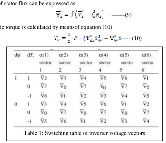
2.3 Inverter optimal Switching Table
On the basis of the torque and flux hysteresis status and of the stator flux switching sector, which is denoted by α, DTC algorithm selects the inverter voltage vector to apply to the induction machine from the Table 1. The outputs of the switching table are the settings for the switching devices of the inverter. Figure 4 shows the relation of inverter voltage vector and the stator flux switching sectors.
----(11)
Active switching vectors are ; ; ; ; ;
Zero switching vectors are ; ;[8]
III SLIDING MODE CONTROLLER (SMC)
Sliding mode controller is suitable for a specific class of nonlinear systems. This is applied in the presence of modeling inaccuracies, parameter variation and disturbances, provided that the upper bounds of their absolute values are known. Modeling inaccuracies may come from certain uncertainty about the plant (e.g. unknown plant parameters), or from the choice of a simplified representation of the system dynamic. Sliding mode controller design provides a systematic approach to the problem of maintaining stability and satisfactory performance in presence of modeling imperfections [9].
SMC is known for its capability to cope with bounded disturbance as well as model imprecision which makes it ideal for the robust nonlinear control of induction motor drives .To design a sliding mode speed controller for the induction motor DTC drive, consider the mechanical equation:
ώ ω + TL
J B
T
P P
Where ω is the rotor speed in electrical rad/s, rearranging to get:
ώ B ω PTL PTe
J J J
--- (13)
Considering Δa and Δb as bounded uncertainties introduced by system parameters J and B, the equation(13) can be rewritten as [10]:
ώ = ( a + Δ ) ωa ( + Δ b )b Te c TL
--- (14)
Where
, ,
B P P
a b c
J J J
Defining the state variable of the speed error as:
* ( ) ω ( ) ω ( )
e t t t --- (15)
( ) é ( )
d
e t t
d t
---- (16) Combining equations (14), (15)
.
( ) ( ) [ e ( ) ]
e t a e t b T d t
---- (17) Where * ω , e e a T T b
d t( ) Δa ω ΔbTe cTL
b b b
---- (18) Defining a sliding surface s(t) from the nominal values of system parameters a and b [10][11]
0
( ) ( ) ( ) ( τ ) τ
t
s t e t
a b k e d--- (19)
Such that the error dynamics at the sliding surface s (t ) = s t( ) = 0 will be forced to exponentially decay to zero, then the error dynamics can be described by:
e
(t ) = (a + bk ) e(t ) ---(20) Where k is a linear negative feedback gain .
Variable structure speed controller k e t( )β s g n ( )s ---(21)
Where β is known as hitting control gain used to make the sliding mode condition possible and the sign function can be defined as
1 if s>0
238 | P a g e To guarantee the existence of the switching surface consider the lyapunov function [12]. Based on Lyapunov Theory, if the function ύ(t) is negative definite , this will ensure that system trajectory will be driven and attracted towards the sliding surface s(t) and once reached, it will remain sliding on it until the origin is reached asymptotically[12].
v(t)= ----(23)
Taking the derivative of equation (23) and substituting the equation (19)
----(24)
Using the equations (17), (21) --- (25)
To ensure the equation (25) always negative definite , the value of hitting control gain β should be designed as the upper bound of the lumped uncertainties d(t) i.e β > │ d(t) │
The hitting control gain β has to be chosen large enough to overcome the effect of any external disturbance [12][13]. Therefore the speed control law defined in will guarantee the existence of the switching surface s(t) in and when the error function e(t) reaches the sliding surface, the system dynamics will be governed by which is always stable [10]. Moreover, the control system will be insensitive to the uncertainties ∆a , ∆b and the load TL.
IV FUZZY BASED SLIDING MODE CONTROLLER
The sign function in the sliding mode control will cause high frequency chattering due to the discontinuous control action which represents a severe problem when the system state is close to the sliding surface [6]. To overcome this problem a boundary layer Φ is introduced around the switching surface and the sign function will be replaced by a saturation function sat(s /Φ) [6]. The choice of Φ is crucial; small values of Φ may not solve the chattering problem and large values may increase the steady state error, requiring a compromise choice when selecting the boundary layer thickness.
To reduce the chattering phenomenon is to combine FL with a SMC [6]. Hence two new Fuzzy Sliding Mode (FSM) controllers are formed with the robustness of SMC and the smoothness of FL. The switching functions of
sliding mode and FSM schemes are shown in Figures5,6. In this technique the saturation function is replaced by a fuzzy inference system to smooth the control action.
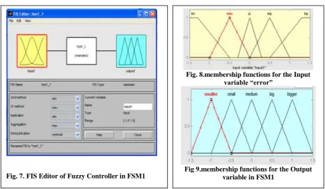
4.1 FSM1
The fuzzy sliding mode controller1 is shown in Fig. 7 to Fig.9.
Table2:Fuzzy rules for FSM1
Input(e) bn mn jz mp bp
output bigger big medium small smaller
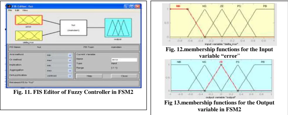
4.2 FSM2
The inputs given to the FSM2 are two and are shown in the fig10[14]. the matlab models of fuzzy controolers are shown in the figures11 to 13. The membership functions for the first input ―error‖ is same as in FSM1. The fuzzy rules ar taken trial and error to get the optimized response. Fuzzy rules are shown in the table3.
Fig. 8.membership functions for the Input variable “error”
Fig 9.membership functions for the Output variable in FSM1
240 | P a g e The membership functions for the input fuzzy set error , output is same as in FSM1.Where as the membership functions for the second input is shown in the figure12.
Table3: Fuzzy Rules for FSM2
e/de NB NS ZE PS PB
NB ZE PS PB PS ZE
NS NS ZE PS ZE NS
ZE NB NS ZE NS NB
PS NS ZE PS ZE NS
PB ZE PS PB PS ZE
V RESULTS
Fig.14: ZN - No load - Stator Currents. Fig.15: ZN - No load - Torque Response
Fig.16: ZN -No Load - Speed Response Curve. Fig.17: ZN- Load-Stator Currents.
Fig.18: ZN - Load-Torque Response Fig.19: ZN - Load - Speed Response Curve. Fig. 11. FIS Editor of Fuzzy Controller in FSM2
Fig. 12.membership functions for the Input variable “error‖
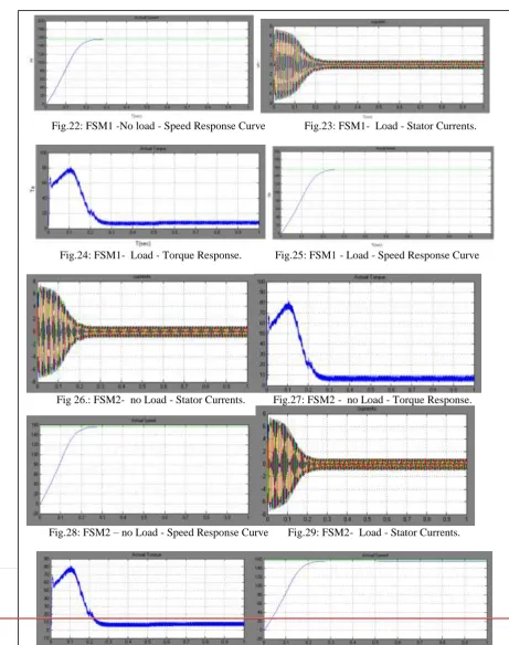
241 | P a g e Fig.20: FSM1- No load - Stator Currents. Fig.21: FSM1 - No load - Torque Response
Fig.22: FSM1 -No load - Speed Response Curve Fig.23: FSM1- Load - Stator Currents.
Fig.24: FSM1- Load - Torque Response. Fig.25: FSM1 - Load - Speed Response Curve
Fig 26.: FSM2- no Load - Stator Currents. Fig.27: FSM2 - no Load - Torque Response.
242 | P a g e Compared the speed controller s of ZN, SM, and FSM based methods. The figures 14 to 31 shows the stator currents, torque, speed response curves of ZN,FSM1,FSM2 based controllers without load and with step change in load T=9N-m applied at 0.5 seconds .
Response
Specifications
Ziegler-Nichols
method
Kp=0.612,
ki=122.4
SMC FSM1 FSM2
ITAE 4.46 0.5 0.49 0.3718
Speed response settling time in sec
0.44 0.25 0.22 0.2
Transient response 2.77% overshoot No overshoot No overshoot No overshoot
Response to load torque application (load torque 9N-m is
applied at 0.5 sec)
Speed drops to 152 rad/sec from
155 rad/sec
Speed drops to 156 rad/sec
from 157 rad/sec
Speed drops to155.5 rad/sec from 156 rad/sec then quickly regained the reference
speed
Speed drops to155.5 rad/sec from 156 rad/sec then quickly
regained the reference speed Table4: comparison of results of ZN, SMC, FSM1, FSM2 controllers.
VI CONCLUSION
Simulation has been carried out for ZN, SMC, FSM1 and FSM2 controllers with no load and load of 9N-m applied at 0.5 sec, The results are tabulated in the table4. The controller coefficients used in FSM are k=-2.3e-4, β=100[7]. ITAE is very less in FSM1 FSM2 based controllers.FSM2 has less ITAE and reached steady state in 0.2 seconds. And there was no overshoot in both SMC, FSM1,FSM2 bases controllers
MOTOR
PARAMETERS
P=4, Rs=7.83Ω,Rr=7.55Ω,Ls=Lr=0.4751H,Lm=0.4535H,Vdc=400V,J=0.03kg/m3,B=0.006,P=1.5Kw,TL=9N-m,
NRATED=1480rpm(155rad/sec)
REFERENCES
[1] Takahashi, I. And Y. Ohmori, ―High Performace direct torque control of induction motor,‖
IEEE Trans. Ind. Appl. 25 (2): pp. 257-264, 1989.
[3] Lin Feng, Zheng Hongtao and Yang Qiwen, ―Sensorless vector control of induction motors based on online GA tuning PI controllers‖, Fifth International Conference on Power Electronics and Drive Systems. IEEE ,Singapore Vol.1, 2003, pp.222-5 Vol.1.
[4] Nagubandi Mahesh, Rupansi Batra,‖ Tuning of PI Speed Controllers in DTC of Induction Motor based on
Sliding Mode and Fuzzy Sliding Mode Controllers‖, IRACST-IJCNWC, Vol.4, No.2, April 2014.
[5] H.F.Abdul Wahab and H.Sansui, ―Simulink Model of Direct Torque Control of Induction
Machine,‖American Journal of Applied Sciences 5(8):1083-1090,2008, ISSN 1546-9239©2008 Sciences Publications
[6] R.Toufouti, S.Meziane, and H.Benalla, ―Direct Torque Control of Induction Motor Using Fuzzy Logic,‖ ACSE Journal, Volume (6), Issue (2), pp.19-26, June 2006.
[7] K. Gurunath Sudheer, V.Kishore ―a control strategy speed controller for Direct torque control of induction Motor drive using genetic algorithm Optimized proportional-integral and Fuzzy sliding mode,‖ IJEEAR,Vol.03,Issue 02, pp 159-166, May-June 2012.
[8] R.Toufouti S.Meziane ,H. Benalla, ―Direct torque control for induction motorusing intelligent techniques‖, Journal of Theoretical and Applied Information Technology,pp35-44,2007.
[9] Stanislaw H. Zak, systems and control ( New York: Oxford University Press, 2003).
[10] V. I. Utkin,―Sliding Mode control design principles and applications to electric drives,‖ IEEE Trans. Ind. Electron., Vol. 40, No. 1, pp. 23-36, Feb. 1993.
[11] F.J.Lin, W.D.Chou and P.K.Haung ―Adaptive Sliding-mode Controller based on Real-time Genetic algorithm for Induction motor Servo Drive,‖ IEE Proce.Electr. Power Appl. Vol.150, No.1, pp.1-13, January 2003.
[12] J. Lo and Y. Kuo, ―Decoupled Fuzzy Sliding Mode Control,” IEEE Trans. Fuzzy Syst., Vol.6, No. 3, pp.
426-435, Aug. 1998.
[13] F. Barrero, A. Gonzalez, A. Torralba, E. Galvan and L. G.Franquelo, ―Speed control of Induction Motors uses a novel Fuzzy Sliding Mode structure,‖ IEEE Trans. Fuzzy Syst., Vol.10, No.3, pp. 375-383, June 2002.
[14] S.M. Gadoue, D. Giaouris, J.W. Finch, ‖Artificial intelligence-based speed control of DTC induction motor
drives—A comparative study‖, Electric Power Systems Research, Vol.79, pp210-219, 2009.
[15] Jing-Chung Shen, ―Fuzzy Neural Networks for Tuning PID Controller for Plants with Underdamped Responses‖, IEEE Transactions on Fuzzy Systems, Vol.9, No.2, April 2001.
[16] Kuo-Kai shyu and Hsin-Jang Shieh ―A New Switching Surface Sliding-Mode Speed Control for Induction MotorDrive Systems,‖ IEEE Transactions on Power Electronics, Vol.11, No.4, pp.660-667, July 1996.
AUTHORS PROFILE
244 | P a g e Faridabad. He is currently working as Lecturer, School of Electrical & Computer Engg., Hawassa Institute of Technology- Hawassa University, Ethiopia. He is an active member of IEEE. His Areas of interest are Artificial Intelligent control Techniques, Robotics, Realibility, Power Electronics, Power System Operation and Control, Robust Control Systems,Non-linear Control Systems.