© 2019, IRJET | Impact Factor value: 7.211 | ISO 9001:2008 Certified Journal
| Page 732
DESIGN MODIFICATIONS OF CAR FRONT RAIL AND ITS’ ANALYSIS
Shivangi Yadav
1, Raghvendra Krishana
1, Ajay Srivastava
21
Post Graduate (Mechanical Engineering), Institute of Engineering and Technology, Lucknow
2
Project Engineer, ETA INC, India/USA
---***---Abstract: Frontal crash is one of the major forms of accident in the present scenario. It has become very important to design frontal structures that have sufficient load taking capacity with appreciable deformation. This research paper analyzes the front load beam of car to reduce occupant’s injuries. The present work utilizes the Finite Element Analysis for the dynamic evaluation and proposes certain modifications in the existing design for the car front rail so as to increase the load carrying capability of the front rail and maintain sufficient survival space for the occupants at the same time. Impact speed of 48 km/h (AIS-096) under dynamic conditions was used to evaluate the energy absorption under the dynamic simulation.
Keywords: Frontal crash, finite element analysis, energy
absorption, dynamic.
1. INTRODUCTION
The frontal rails that are present between the front bumper and the dash toe pan are the structural members that form an integral part of the energy absorbing area in the front crumple zone. These front members absorb great amount of energy during frontal impact and prevent the impact energy from being transferred to the passengers or the driver [1].
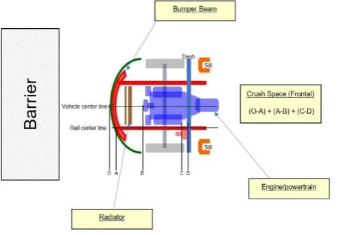
[image:1.595.37.286.560.731.2]The maximum amount of impact energy has to be managed in the crush space available at the front region of the vehicle. This can be seen in the figure 1.1.
Figure 1.1 Crush space management
Dadrasi Ali [2] discussed the effect of increasing some parameters and its impact on specific energy absorption (SEA) in his paper as given below -
Effect of impact mass: SEA increased Effect of impact velocity: SEA increased Effect of thickness: SEA decreased Effect of column length: SEA decreased
Salehghaffari et al. [3] stated experimental analysis with the objective to enhance the crashworthiness characteristics of metal tubes cylindrical in shape, by utilizing two new design solutions for their structure. They showed that the design methods that have been developed significantly enhanced the crashworthiness characteristics of the metal tubes that are cylindrical.
Heung-Soo Kim[4]divided the front rail into two parts i.e. a part that collapses axially and a part that collapses due to bending load, and the response of each of these two parts was studied during crush by altering wall thickness as well as the foam strength of aluminium. It was found that a significant increment in the absorption of energy and efficiency in weight was gained by filling aluminium foam in the front side rail structure.
Oscar et al. [5] evaluated the performance during crashworthiness of spot-welded columns made out of advanced high strength steels using Finite Element Analysis (FEA). They showed that the DP steels exhibit greater energy absorbing properties than the HSLA steel for both hat-type configurations.
Hamouda et al. [6] presented a study of the energy absorption of square tubular structures. Energy absorbing characteristic of metal and composite square tubes with different l/w ratio had been examined experimentally. They showed in their paper that the maximum load carrying capacity of the metal tubes and energy absorption by the metal tubes (mild steel) were higher than those of the other tubes (Kevlar, glass).
© 2019, IRJET | Impact Factor value: 7.211 | ISO 9001:2008 Certified Journal
| Page 733
energy absorption of the parts, before and after the replacement of the material are close to each other.
Alghamdi [8] reviewed the shapes that the energy absorbers having the property of collapsibility, commonly possess and their different deformation modes. The most common shapes comprise tubes that are circular and square, frusta, struts, honeycombs, and sandwich plates. Common deformation modes for circular tubes include axial crushing, lateral indentation, lateral flattening, inversion and splitting.
Shivangi et al. [9] studied the effect of introducing a rib inside the frontal rail upto a definite length and found that it resulted in better energy absorption and reduced vehicle intrusion.
In this research paper, Hyper- mesh (Student Version) has been used as a modelling tool for making the various modifications in the intrusion beam. LS-Dyna has been used as an analysis tool. The proposed designs showed better energy absorption compared to the existing design.
“Design and analysis of car front rail” by Shivangi et al. was taken as the base of this research paper. Further modifications have been made in the design proposed in the above research paper.
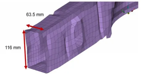
The existing design comprises of section with dimensions as 63.5 mm x116 mm x 1.4 mm. The length of the section was 250 mm. Figure 1.2 shows the dimension of the rectangular section, which is used in existing vehicles [9].
Figure 1.2 Front Rail existing design – dimensions [9]
[image:2.595.315.559.92.228.2]Figure 1.3 shows the proposed design 1 that consists of cross ribs. Rib length in the positive x-direction was 165 mm and the thickness of the front rail was changed at a distance 173 mm from rail front end which was 1.6 mm and it was up to 78 mm in the positive x-direction. The thickness of the cross ribs was 1.4 mm [9].
Figure 1.3 Front rail proposed design 1 [9]
2. METHODOLOGY
[image:2.595.315.562.377.546.2]A 3D specimen model of the same dimension as in existing design [9] was made on Hyper-mesh software. Fine mesh with quads and trias and average mesh size 4 mm was used for meshing. The mesh size has been selected based on the convergence test. The minimum and maximum size of the elements were 2 mm and 5 mm respectively. Figure 2.1 shows the convergence graph.
Figure 2.1 Convergence graph
[image:2.595.42.271.503.624.2]Table 1 shows the quality criteria used during meshing.
Table 1 Mesh Quality Criteria
Shell Element warpage in
Degrees <15, Degrees
Minimum Element size for
shell Elements 2 mm
Maximum Element size for
shell Elements 5 mm
© 2019, IRJET | Impact Factor value: 7.211 | ISO 9001:2008 Certified Journal
| Page 734
Element Jacobian of the Shell
Element >0.6, =1
Skewness of Shell Element <45, Degrees
Percentage of Trias <= 7%
2.1 DESIGN MODIFICATIONS
[image:3.595.318.557.139.261.2]Proposed design 1 modified has been created from proposed design 1 [9]. The inner ribs of the front rail have been moved inside. Ribs are connected at distance 50 mm from the front end of the rail and are connected with the rails at edges as shown in figure 2.1.1.
Figure 2.1.1 Proposed design 1 modified
In proposed design 2, the rectangular section has been created by welding a side plate to the C- section. The thickness of the C- section is 1.55 mm and side plate is 1.63 mm. The length of the rail is 680 mm as shown in figures 2.1.2 and 2.1.3.
Figure 2.1.2 Proposed design 2 - Isometric view
Figure 2.1.3 Proposed design 2 - Front region of the front rail
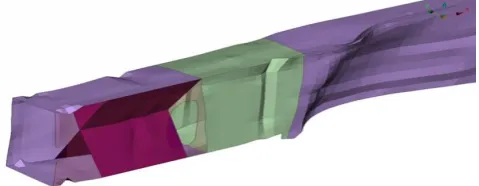
[image:3.595.40.280.275.368.2]In proposed design 3, two 1.2 mm thick plates were added inside the front rail as shown in figure 2.1.4 and figure 2.1.5.
Figure 2.1.4 Proposed design 3 - Isometric view
Figure 2.1.5 Proposed design 2 - Front region of the front rail
[image:3.595.321.553.303.420.2]Figure 2.1.6 shows the dimensions of the plate that has been used in the proposed design 3 of the front rail.
Figure 2.1.6 Dimension of plates in front rail
3. RESULTS AND DISCUSSIONS
[image:3.595.318.533.499.619.2]© 2019, IRJET | Impact Factor value: 7.211 | ISO 9001:2008 Certified Journal
| Page 735
and rigid zone. The effect of this is that the rails is undergoing crushing and bending.
Figure 3.1, 3.2. 3.3, 3.4 and 3.5 shows the crushing and bending phenomenon in the front rails in existing design, proposed design 1, proposed design 1 modified, proposed design 2 and proposed design 3 respectively at 40 ms after the impact.
[image:4.595.38.558.98.788.2]Figure 3.1 Existing design
Figure 3.2 Proposed design 1
Figure 3.3 Proposed design 1 modified
Figure 3.4 Proposed design 2
Figure 3.5 Proposed design 3
Figure 3.6 shows the energy absorption graph of existing design, proposed design 1, proposed design 1 modified, proposed design 2 and proposed design 3. It can be clearly seen that there is approximately 45% more energy absorption in proposed design 3 compared to the existing design.
Figure 3.6 Combined graph of energy absorption
[image:4.595.318.561.559.688.2]© 2019, IRJET | Impact Factor value: 7.211 | ISO 9001:2008 Certified Journal
| Page 736
[image:5.595.39.289.142.275.2]clearly seen that there is approximately 10% reduction in vehicle intrusion in proposed design 3 compared to existing design.
Figure 3.7 Combined graph of vehicle intrusion
4. CONCLUSION
The proposed designs as well as existing design were studied using LS-Dyna explicit code and the energy absorption was studied during their deformation under full frontal impact. The proposed designs significantly improved the energy absorption of the front rail. The results show that the strength and energy absorption ability of front rail depends upon the cross-section and material properties of the rails. Present study is useful for the automotive engineers to optimize the weight and materials of the front rails to absorb more energy during impact to improve passenger safety.
REFERENCES
[1] Joseph, R. and Kamoji, M.A., 2015. Crash Analysis for Energy Absorption of Frontal Rails of a Passenger Car. Joseph, R. and Kamoji, M.A., 2015. International Research Journal of Engineering and Technology. Volume: 02, Issue: 03, pp: 09-13.
[2] Dadrasi, A., 2012. An investigation on crashworthiness design of aluminium columns with damage criteria. Res J Recent Sci, Volume: 01, pp:19-24.
[3] Salehghaffari, S., Tajdari, M., Panahi, M. and Mokhtarnezhad, F., 2010. Attempts to improve energy absorption characteristics of circular metal tubes subjected to axial loading. Thin-Walled Structures, Volume: 48, Issue: 06, pp: 379-390.
[4] Kim, H.S., 2010. Analysis of crash response of aluminium foam-filled front side rail of a passenger car. International journal of crashworthiness, Volume: 06, Issue: 02, pp: 189-208.
[5] Oscar, P. and Eduardo, R.L., 2008, July. Impact performance of advanced high strength steel thin-walled columns. In Proceedings of the world congress on engineering, Volume: 02, pp: 02-04.
[6] Hamouda, A.M.S., Saied, R.O. and Shuaeib, F.M., 2007. Energy absorption capacities of square tubular structures. Journal of Achievements in Materials and Manufacturing Engineering, Volume: 24, Issue: 01, pp: 36-42.
[7] Li, Y., Lin, Z., Jiang, A. and Chen, G., 2003. Use of high strength steel sheet for lightweight and crashworthy car body. Materials & design, Volume: 24, Issue: 03, pp: 177-182.
[8] Alghamdi, A.A.A., 2001. Collapsible impact energy absorbers: an overview. Thin-walled structures, Volume: 39, Issue: 02, pp: 189-213.