© 2019, IRJET | Impact Factor value: 7.211 | ISO 9001:2008 Certified Journal | Page 5478
MAGLEV WIND TURBINE GENERATOR
Atharva Mandle
1, Dr. B P Saoji
2, Ayushi Agrawal
1, Shrutika Kale
1, Abhijeet Karkhanis
11Student, Dept. of Instrumentation, Bharati Vidyapeeth College of Engineering, Navi Mumbai, Maharashtra, India 2Professor, Dept. of Instrumentation, Bharati Vidyapeeth College of Engineering, Navi Mumbai, Maharashtra, India
---***---Abstract - Wind energy is the fastest growing source of clean energy worldwide. As per data from the Global Wind Energy Council, the employment of wind energy is expected to increase dramatically over the next few years. This paper provides a detailed idea on the making and working of a MAGLEV Wind Turbine Generator (hereon referred to as MWTG). It makes use of the speed and direction of wind to propel its blades and produce electricity. We aim to try to provide a valid and handy substitute for fossil fuels that can then be taken up by many countries worldwide. This requires one such Green energy that will not only provide more power but also reduce the problems like Global warming, Ozone layer depletion and green-house gases. Two types of wind turbines- Vertical Axis and Horizontal Axis are available to choose from. Vertical Axis Wind Turbine is one method to provide a substitute for solar energy consumption. We will observe how to increase overall production of energy with the help of a non-renewable resource, thereby fulfilling our objectives.
Key Words: Wind Energy, Generator, Turbine, Vertical, Axis, substitute.
1.
INTRODUCTION
In order to create a better method of conserving energy and using the already available resources in a more easy and compliant way, we have chosen to make MWTG that can be readily present beside all our highways and roads. As the direction of wind doesn’t matter, we can install these wind turbines on divider of highways and major roads. Even at lower velocities this turbine will rotate and generate energy. With multiple such setups connected in series, we can charge a battery quickly or produce more energy to power displays and other such devices.
Furthermore in order to increase power production in the device, we found another way to use less resources and an overall improvement in the system. This can be done by introducing another concept in the turbines which is of Maglev.
2.
OVERVIEW
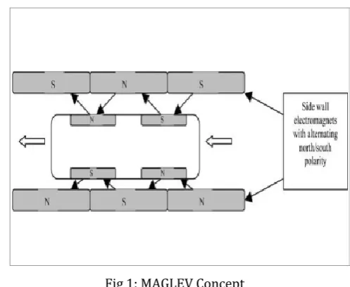
Maglev is a term derived from magnetic levitation. It is a system of transportation that does suspension, guides and propels vehicles, using magnetic levitation. This method can be faster easily, quieter and smoother than wheeled mass transit systems that were generally used earlier. For levitation, a large power is usually not needed of the overall consumption; while most of the power used is needed to overcome air drag.
[image:1.595.318.567.417.621.2]A pair of permanent magnets like neodymium magnets is used here and substantial support magnetic levitation can easily be experienced through it.
Fig 1: MAGLEV Concept
© 2019, IRJET | Impact Factor value: 7.211 | ISO 9001:2008 Certified Journal | Page 5479 2.1
Objectives:
Provide substitute for fossil fuels.
Increase overall energy production. 2.2
Problem Definition:
In order to create a better method of conserving energy and using the already available resources in a more easy and compliant way, we have chosen to make VAWT that can be readily present beside all our highways and roads.
3.
REVIEW OF LITERATURE
Using wind turbines isn’t a new concept and has been tried before using various methods to reduce errors and maximize power generation. Usually there remains at least one drawback in each type no matter what the changes are made. Maglev type remains one of the best out of them in concerns of more power and less maintenance thereby giving maximum optimization.
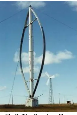
[image:2.595.357.512.233.395.2]Primarily there are two distinct types of vertical axis wind turbines: The Darrieus and the Savonius types. The Darrieus rotor was looked into and developed extensively by the Sandia National Laboratories in the USA in the 1980's. Following this, new and better concepts of vertical axis wind machines are being introduced. The helical types are particularly for use in urban environments where they would be considered safer due to their lower rotational speeds avoiding the risk of blade ejection and also because they can catch the wind from all directions.
Fig 2: The Darrieus Type
The Darrieus Type: The first aerodynamic vertical axis wind turbine was developed by Georges Darrieus in France and first patented in 1927. Principle of operation of this type depends on the
[image:2.595.95.226.500.694.2]fact that its blade speed is a multiple of the wind speed, which results in an apparent wind throughout the whole revolution. The original Darrieus (shown in Fig 1) turbine suffered from some negative features such as violent vibrations leading to eventual fatigue blade failure, a high noise level and a relatively low efficiency, which severely limited its success.
Fig 3: The Savionus Turbine
The Savionus Turbine: It is a vertical axis machine which uses a rotor that was introduced by Finnish engineer S. J. Savonius in 1922. In its simplest form (shown in Fig 2) it is essentially two cups or half drums fixed to a central shaft in opposing directions. Newly used Savonius machines have since evolved into fluted bladed devices, which have a higher efficiency and less vibration than previous ones.
Ropatec vertical wind turbine: They were developed in Italy and are neither proper Darrieus nor Savonius but a hybrid design. The wind rotors used in this type are made from airfoil sections like those of an airplane wing. A central panel between the wings, acts as a diffuser and directs the wind flow toward the wings, turning the wind rotor at low wind speed.
© 2019, IRJET | Impact Factor value: 7.211 | ISO 9001:2008 Certified Journal | Page 5480 In this way many Vertical Axis Wind Turbines have
have been developed over the years. Using many techniques the effort, cost, pollution, etc numerous types were designed and Maglev Wind Turbine is one such successful invention.
Vertical axis turbines are now shown as being capable of catching the wind from all directions and do not need yaw type mechanisms to function.
One can foresee some future where each human dwelling in the world is equipped with wind generators and solar collectors, as global peak petroleum is reached making them indispensible for human wellbeing. These ones are well suited for green buildings, some complex architectural projects as well as futuristic aquaponics; where vertical farming in a skyscraper uses automated technologies.
A hybrid model of a solar/ wind used in Simulink, which is using battery as its storage system is developed. This innovative simulation includes all realistic components of the system. In this system, the power delivered by the combine system component is compared with each other and various conclusions are drawn after. A comparative study of hybrid model solar /wind system is done and this is spoken of solar-wind hybrid system for supplying electricity to power grid of the world.
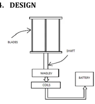
[image:3.595.391.473.412.521.2]4.
DESIGN
Fig 4: Block Diagram
4.1
Components:
1. Blades (10 pieces, made of acrylic sheets of 0.25 cm thickness x 15 inch height )
2. Shaft
3. Rotor
4. Magnets (16 pieces- neo dymium magnets of 5mm x 3mm, 1 piece-mid magnet of Inner and outer Diameter (OD 6" and ID 2")
5. Coils (3 inch diameter)
6. Windings
Design of Base: In this project there is a pole base can be with stand, in large force of wind. The base of the model & its height are related to cost and transmission system incorporated together.
Design of blade: Wind turbine blades that are used here have on aerofoil– type and a variable pitch. While designing the size of blade it is must to know the weight and cost of blades in the project ten blade with vertical shaft are used, it has a height & width of 38cm & 0.25cm respectively.. The angle between two blades is 360. It happens so that if one blade moves other
[image:3.595.76.238.479.656.2]blades comes in the position of first blade, so the speed is increases.
Fig 5: Blade placement
Shaft Designing: While designing the shaft of blades it is important to see the proper fitting of the blades on it. It should be as less in thickness as possible & light in weight. The shaft used is very thin in size and are all properly fitted. So no problem of slipping & fraction is created, it is made up of hollow Aluminium which is having very light weight.
© 2019, IRJET | Impact Factor value: 7.211 | ISO 9001:2008 Certified Journal | Page 5481 internal combustion engines. Alternators in power
stations driven by steam turbines are called turbo-alternators and are used here similarly.
Magnets: Neodymium Magnets are used, which are a member of the Rare Earth magnet family from all others. They are the most powerful permanent magnets in the world.
Another magnet is used for levitation purpose between neo and coils, i.e. Mid Magnet.
5.
METHODOLOGY
5.1 Working Principle:
The turbine works on the principles of wind power, the generator, magnet levitation and the DC-DC converter.
This device can make use of 2 types of axis: Horizontal and Vertical. Horizontal Axis- It needs higher wind velocities of which the direction is important. It is very high power. But the efficiency is only 18 to 20%. Vertical Axis- In this the generator can be placed on ground. Also it works on lower wind velocities as well wherein the direction of wind is not important. It generates medium power. But the efficiency is as much as 50 to 60%. So, we chose the Vertical Axis for our model.
Further in order to reduce pollution, noise and maintenance and thereby maximize optimization we decided to add in another concept of Maglev i.e Magnetic Levitation. It serves as a better option in the following ways- 1 Maglev wind turbine powers 750 thousand homes when a 1000 standard wind mills would be needed to power 500 thousand homes. The Maglev one requires less than 100 acres while a 100 standard ones need more than 64,000 acres of land. The cost, noise and resource are also higher in case of the standard wind mills in comparison with the Maglev wind Turbine.
A wind turbine generator is made up of two major components that can be explained simply as- the turbine blades which are spun by the wind, and an alternator which converts wind energy into electricity. While it is possible to purchase a sealed alternator unit, it is not particularly difficult to make your own alternator using neodymium magnets and magnet wire.
5.2
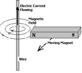
Generating Electricity:
[image:4.595.366.510.252.381.2]All these alternators work because of the effects of moving magnets past wire near the coil. When these internal electrons flow through a wire, a simultaneous magnetic field is created around it. Similarly when a magnetic field moves past a wire, internally electrons are pushed through it as well. Therefore, by moving magnets past a wire we make electrons move through it, thereby generating electricity.
Fig 6: Magnet Flow
If we have many individual wires instead of a single wire (pictured above), the same current of electricity will be generated in each wire equally. We should remember, it is not practical to have lots of connected individual wires in an alternator. So coils of wire are instead used by us for quicker understanding.
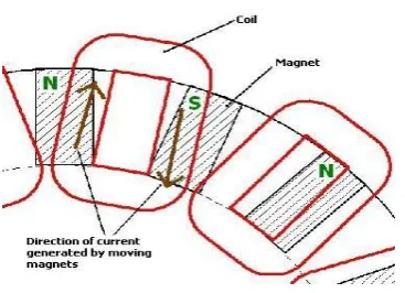
5.3 Coils and Magnets:
When the north pole of a magnet passes a coil, around the coil, current flows in one direction and when the south pole of a magnet passes a coil, current flows in the opposite direction.
© 2019, IRJET | Impact Factor value: 7.211 | ISO 9001:2008 Certified Journal | Page 5482 Fig 7: Magnet position
In the diagram above it can be seen how electric current in the left radial leg of the coil is pushed upwards (clockwise) by the north pole of one magnet, and in the right radial leg it is pushed downwards (also clockwise) by the south pole of the next magnet.
Considering, both radial legs were over magnets with the same polarity - i.e. the left side of the coil generating a current in the clockwise direction, and the right side of the coil that is generating a current in the anticlockwise direction resulting in no current flowing around the coil that is zero current. Therefore alternator rotors are made up of magnets with alternating polarities - N S N S and so on, and the coils are sized so that the distance between the two legs is equal to the distance between two side-by-side magnets near the coil are placed.
5.4
Voltage and Current:
Here, the voltage and current generated now depends on: the strength of the magnets, the number of turns of wire in the coils, the distance between the coils and the magnets present. The polarity of the voltage - i.e. the direction the electricity flows depends on the polarity of the magnet - north or south.
The voltage output by an alternator made of coils and magnets is therefore Alternating Current (AC), with the direction of the current changing every time the legs of the coils pass over a magnet.
6.
CALCULATIONS
The MWTG works on the principle of converting kinetic energy of the wind to mechanical energy. The kinetic energy of any particle is equal to one half its mass times the square of its velocity, or can also be written as ½ mv2.
K.E = ½ mv2 ……….. (1)
K.E = kinetic energy m = mass
v = velocity,
M is equal to its Volume , multiplied by its density of air
M = AV ……….. (2) Substituting eq(2) in eq(1)
We get, K E = ½ AV.V2
K E = ½ AV3 watts = density of air
= ( 1.225 kg/m3 )
A = D2 /4 ( Sq. m )
(D = diameter of the blade) A = *(1.22) 2 /4
A = 1.16Sq.m Available wind power,
Pa = (½ D2 V3 )/4
P = 1/8 D2 V3 watt
7.
RESULTS
Wind
Velocity
(m/s)
Maglev Vertical Axis Wind Turbine
Speed
(rpm)
Electric
Potential(V) Power (W)
1.5 85 3.6 0.07
2.4 128 5.8 0.19
3.2 162 7.5 0.32
4.6 232 10.7 0.67
5.5 261 12.1 0.85
6.7 303 13.8 1.12
7.1 Applications:
© 2019, IRJET | Impact Factor value: 7.211 | ISO 9001:2008 Certified Journal | Page 5483 can install these wind turbines on divider of
highways and major roads.
2. Even at lower velocities this turbine will rotate and generate energy.
3. With multiple such setups connected in series, we can charge a battery quickly or produce more energy to power displays and other such devices.
8.
CONCLUSION
By the process of making a Maglev Wind Turbine Generator we have learned- the concept of Magnetic Levitation. We have also observed how to increase the overall production of energy with the help of one non-conventional resource, thereby fulfilling our objectives.
From this project it can be seen that our work and the results obtained so far are very encouraging. They reinforce the conviction that vertical axis wind energy conversion systems using Maglev are practical. These systems are also potentially very contributive to the production of clean renewable electricity from the wind even under less than ideal sitting conditions. We can hope for future that they may be constructed using high-strength, low- weight materials for deployment in more developed nations and settings or with very low tech local materials and local skills in less developed countries.
9.
REFERENCES
1. Aman Jain, Aditya Gupta, Dinakar Singh & Kamal Sharma : “Review paper on Maglev Wind Turbine
2. Dr. Murat Koksal and Dr. Larry Hughes , Dalhousie University.
3. J Berrocal, Brain Dolan, M Tangredi : “Design of Vertical Axis Wind Turbine to Power LED Street Light”
4. M. Ragheb: “Vertical Axis Wind Turbines” 2015