Post-Buckling Stability Analysis of Composite Laminated Flat Plates
with Initial De
fl
ection under Biaxial Compression
+1Keiichi Nemoto
1, Hirakazu Kasuya
2,+2, Hisao Kikugawa
3and Tooru Kohiga
4,+31Department of Aerospace Engineering, The Yokohama Rubber Co., Ltd., Hiratsuka 254-8601, Japan
2Department of Prime Mover Engineering, School of Engineering, Tokai University, Hiratsuka 259-1292, Japan
3Department of Biomedical Engineering, School of Engineering, Tokai University, Hiratsuka 259-1292, Japan 4Course of Mechanical Engineering, Graduate School of Engineering, Tokai University, Hiratsuka 259-1292, Japan
Advancedfiber-reinforced laminated plates have been used as structural members in various applications by virtue of their high specific strength and stiffness. This paper considers, by use of the second variation of the total potential energy, secondary buckling of cross-ply laminated plates with an initial deflection under biaxial compression that is simply supported along four edges. The occurrence of secondary buckling is proven analytically and the effects of the initial deflection, outer lamination angle, number of layers, biaxial compressive load ratio and post-buckling deflection pattern are discussed. [doi:10.2320/matertrans.M2013111]
(Received March 21, 2013; Accepted May 31, 2013; Published July 12, 2013)
Keywords: structural analysis, composite materials, post-buckling behavior, biaxial compression, composite laminated plates, outer lamination angle, initial imperfection
1. Introduction
The use of advanced composite materials such as carbon-fiber-reinforced plastic has found an increasingly wide range of industrial applications because of their excellent properties such as a high specific strength and specific stiffness. In particular, the weight percentage of composite materials relative to the entire weight has significantly increased in civil aviation aircraft.
Although the buckling stress is one criterion for designing thin-walled structures, buckled structures often retain their load-carrying capacity without a decrease in the applied compressive load.1)Numerous researchers have discussed the post-buckling behavior of thin plates under in-plane com-pression;2,3)however, few researches have been conducted on the secondary buckling phenomenon, which occurs with a further increase in the load.4)
We previously proposed the secondary buckling behavior of cross-ply laminated plates57) and presented a post-buckling analysis of these plates with initial deflections,8)
but the post-buckling stability under biaxial compressive loads is still unknown.
In this study, we examined the buckling problems of cross-ply laminated plates with initial deflections subject to biaxial compressive loads and expanded on the analytical techniques used previously.58) The stability of the post-buckling
equi-librium states can be discussed in terms of the second variation of the total potential energy. Here, the occurrence of secondary buckling is proven analytically, and the effects of various factors are discussed.
2. Basic Equation of Orthotropic Laminated Plates
[image:1.595.304.547.331.475.2]2.1 Basic relational equation
Figure 1 shows the coordinate system and dimensions of the symmetrically cross-ply laminated plates with initial deflections under biaxial compressive loads of Nx and Ny.
The displacement componentsu,vandware those in thex,y
and z directions, respectively, in the middle surface andw0
denotes the initial deflection. The in-plane nonlinear strain components ¾x,¾yand £xy and the change in the curvatures
¬x, ¬y and ¬xy can be written in terms of the displacement
components as follows.
¾x¼ @u @x þ
1 2
@w @x
2
þ @w
@x
@w0
@x
;
¾y¼
@v @yþ
1 2
@w @y
2
þ @w
@y
@w0
@y
;
£xy¼
@u @y þ
@v @xþ
@w @x
@w @y
þ @w
@x
@w0
@y
þ @w0
@x
@w @y
;
9 > > > > > > > > > > > > > = > > > > > > > > > > > > > ;
ð1Þ
x N
y N
y
N
x N
x(u) z(w)
y(v)
0
a w0
b h
Fig. 1 Configuration and coordinate system of the cross-ply laminated plate with a small initial deflection under a biaxial compressive load.
+1This Paper was Originally Published in Japanese in J. Japan Inst. Metals
76(2012) 302308.
+2Corresponding author, E-mail: kasuya@keyaki.cc.u-tokai.ac.jp +3Graduate Student, Tokai University
[image:1.595.336.551.675.783.2]¬x¼ @2w
@x2 ; ¬y¼ @2w
@y2 ; ¬xy¼ 2 @2w @x@y: ð2Þ
The axial, circumferential and shear strains of the median surface are given in terms of the median surface stresses in the usual form of Hooke’s law for thin plates:
¾x¼ ·x Ex
¹y·y
Ey ; ¾y¼ ·y
Ey ¹x·x
Ex ; £xy¼ ¸xy
Gxy; ð
3Þ
where·xand·yare the in-plane normal stresses and¸xyis the
in-plane shear stress.ExandEyare the moduli of elasticity,¹x
and¹yare Poisson’s ratios, andGxyis the shear modulus. The
membrane forces per unit widthNx,NyandNxyare defined as
Nx¼
Zþh=2
h=2
·xdz¼
Exh
1¹x¹y
@u @x þ 1 2 @w @x 2 þ @w @x @w0 @x
þ¹y
@v @yþ 1 2 @w @y 2 þ @w @y @w0 @y ( ) " # ;
Ny¼
Zþh=2
h=2 ·ydz¼
Eyh
1¹x¹y
@v @yþ 1 2 @w @y 2 þ @w @y @w0 @y
þ¹x @u
@xþ 1 2 @w @x 2 þ @w @x @w0 @x ( ) " # ;
Nxy¼
Zþh=2
h=2
¸xydz¼Gxyh @u
@y þ @v @xþ @w @x @w @y þ @w @x @w0 @y
þ @w0
@x @w @y : 9 > > > > > > > > > > = > > > > > > > > > > ;
ð4Þ
In this paper, the membrane force and bending moment resultants for the symmetrically cross-ply laminate are
Nx Ny Nxy 8 > < > : 9 > = > ;¼
A11 A12 0
A12 A22 0
0 0 A66
2 6 4 3 7 5 ¾x ¾y £xy 8 > < > : 9 > = > ;; Mx My Mxy 8 > < > : 9 > = > ;¼
D11 D12 0
D12 D22 0
0 0 D66
2 6 4 3 7 5 ¬x ¬y ¬xy 8 > < > : 9 > = > ;; 9 > > > > > > > > > = > > > > > > > > > ;
ð5Þ
where Aij(i,j=1, 2, 6) is the extensional stiffness, andDij
(i,j=1, 2, 6) is the bending stiffness of the laminated plate; from these we can then calculate the material constants of the unidirectional composites EL, ET, ¹L, ¹T, GLTand the
lamination angle ª.9) Suffixes L and T denote longitudinal
and transverse, respectively, of thefiber.
The energyUmdue to the strain in the middle of the plate
and the energyUbdue to bending are given by
Um¼12 Za
0 Zb
0 ðNx¾xþNy¾yþNxy£xyÞdxdy; ð6Þ
Ub¼12 Za
0 Zb
0 ðMx¬xþMy¬yþMxy¬xyÞdxdy: ð7Þ
The total strain energy is obtained as a summation of these energies.
¼UmþUb: ð8Þ
By substituting eqs. (3), (5), (6) and (7) into eq. (8), we obtain
¼12
Z a 0 Zb 0 " 1 h Nx2
Ex ¹x Ex þ¹y Ey
NxNyþ
Ny2
Ey
þNxy2
Gxy
þ
(
D11 @ 2
w @x2
2
þ2D12 @
2
w @x2
@2w @y2
þD22 @
2
w @y2
2
þ4D66 @
2
w @x@y
2)#
dxdy: ð9Þ
2.2 Equilibrium and compatibility equations
The equilibrium equations in thex,yandzdirections of a plate with an initial deflection are expressed as follows:
@Nx
@x þ @Nxy
@y ¼0; @Nxy
@x þ @Ny
@y ¼0;
9 > > = > > ; ð 10Þ
D11@ 4
w
@x4 þ2ðD12þ2D66Þ @4w @x2@y2þD22
@4w @y4
¼Nx
@2ðwþw0Þ
@x2
þNy
@2ðwþw0Þ
@y2
þ2Nxy
@2ðwþw0Þ
@x@y
: ð11Þ
The Airy functionFthat satisfies eq. (10) is defined by
Nx¼h@
2
F
@y2 ; Ny¼h @2F
@x2 ; Nxy¼ h @2F
@x@y; ð12Þ
and reduces the equilibrium in the lateral direction, eq. (11), to the form
D11@ 4
w
@x4 þ2ðD12þ2D66Þ @4w @x2@y2þD22
@4w @y4
¼h
(
@2F @y2
@2ðwþw0Þ
@x2 þ @2F
@x2
@2ðwþw0Þ
@y2
2 @2F
@x@y
@2ðwþw0Þ
@x@y
)
: ð13Þ
By eliminating u and v from the in-plane equilibrium of eq. (10), the following compatibility equation can be obtained:
H22@ 4
F
@x4 þ ð2H12þH66Þ @4F
@x2@y2 þH11 @4F @y4
¼1
h
(
@2w @x@y
2
@2w
@x2 @2w @y2 þ2
@2w @x@y
@2w0
@x@y
@2w0
@x2 @2w
@y2 @2w
@x2 @2w0
@y2
)
; ð14Þ
where
H11¼A22A66=H; H12¼ A12A66=H;
H22¼A11A66=H; H66¼ ðA11A22A122Þ=H; H¼A11A22A66A122A66:
Post-buckling behavior can then be studied through the solutions of the nonlinear simultaneous equations of eqs. (9) and (10) involving F and w under the given boundary conditions. Approximate solutions of these equations will be sought because obtaining the exact solutions is very difficult.
2.3 Analysis of post-buckling behavior
The in-plane strain and membrane force are expressed as
w¼@
2w
@x2 ¼0 atx¼0; a;
w¼@
2
w
@y2 ¼0 aty¼0; b;
9 > > = > > ; ð 16Þ
and the in-plane conditions are
u¼const:along y-axis;
Zb
0 Nxdy¼ Nxb; Nxy¼ 0;
v¼const:alongx-axis;
Za
0 Nydx¼ Nya; Nxy¼0: 9 > > > > > > > = > > > > > > > ;
ð17Þ
Here,wandw0 are expressed by the following two terms that correspond to the symmetrical and asymmetrical modes, respectively, along the loading axis:
w¼w11sin ³
ax
sin ³
by
þw21sin 2³
a x sin ³ by ;
w0¼c11sin ³
ax
sin ³
by
þc21sin 2³
a x sin ³ by ; 9 > > > = > > > ;
ð18Þ
wherew11 is the one half-wave number of the buckling half
wave in both thex- andy-directions, andw21is the two
half-wave numbers of the buckling half half-wave in the xdirection and the one half-wave number of the buckling half wave in theydirection. Thec11andc21terms represent the amplitude
of the initial deflection. Substituting eq. (16) into the right-hand side of eq. (14) yields
F ¼21 h2ðw11
2þ2
w11c11Þ
4 16H22cos
2³x a
þ161
H11cos 2³y
b
þ 2
h2ðw21
2þ2
w21c21Þ
4 256H22cos
4³x a
þ161
H11cos 2³y
b
41
h2ðw11w21þw11c21þw21c11Þ
4
H22 1 9cos
3³x a
cos ³y
b
81 4cosð3³x=aÞcosð2³y=bÞ
H22þ36ð2H12þH66Þ2þ16H114
þ 49 cosð³x=aÞcosð2³y=bÞ
H22þ4ð2H12þH66Þ2þ16H114
·xy2
2
·yx2
2 ;
ð19Þ
where=a/b.
When we substitute the deflectionwand stress functionF
into the equilibrium equation in the lateral direction, i.e., eq. (13), the following simultaneous cubic equation is obtained
by applying the Galerkin method. Bothw11 andw21are then
determined by applying the NewtonRaphson method8) to
eqs. (18) and (19). Substituting w and w0 into eq. (11), we
obtain the relationship between the average axial compressive stress·xand the average axial shortening¾mx as follows:
¾mx¼ 1 a
Za
0
@u @x dx
¼ 1
a Za 0 ¾x 1 2 @w @x 2 @w @x @w0 @x ( ) dx
¼H11·xhþ ³
2
8a2ðw11
2þ2
w11c11þ4w212þ8w21c21Þ:
ð20Þ
2.4 Stability criterion of post-buckling
The equilibrium equations can be obtained by equating thefirst variation¤¬of the total potential energy¬to zero, i.e., the stationary potential energy criterion. The stability of the equilibrium state can be determined by the second variation¤2¬:
¤2¼1 2 Z a 0 Zb 0 " 1 h (
¤Nx2
Ex þ ¤Ny2
Ey
¹x
Exþ ¹y
Ey
¤Nx¤Nyþ¤Nxy
2
Gxy
)
þ Nx
@¤w @x
2
þ2Nxy
@¤w @x
@¤w @y
þNy
@¤w @y
2
( )
þ
(
D11 @ 2¤w
@x2
2
þ2D12 @
2¤w
@x2
@2¤w @y2
þD22 @
2¤w
@y2
2
þ4D66 @
2¤w
@x@y
2)#
dxdy; ð21Þ
where
¤Nx ¼1Ex¹x¹yh
@¤u @x þ
@w @x
@¤w @x
þ @w0
@x
@¤w @x
þ¹y @¤v
@y þ @w @y
@¤w @y
þ @w0
@y
@¤w @y
;
¤Ny ¼1Ey¹h x¹y
@¤v @y þ
@w @y
@¤w @y
þ @w0
@y
@¤w @y
þ¹x
@¤u @x þ
@w @x
@¤w @x
þ @w0
@x
@¤w @x
;
¤Nxy ¼Gxyh
@¤v @x þ
@¤u @y þ
@¤w @x @w @y þ @w @x
@¤w @y
þ @w0
@x
@¤w @y
þ @¤w
@x @w0 @y : 9 > > > > > > > > > > > > > > > > > > > > > > > > > > > > > > > > > > > = > > > > > > > > > > > > > > > > > > > > > > > > > > > > > > > > > > > ;
ð22Þ
If ¤2¬ is positive, the equilibrium state is stable; if it is
judged independently of the assumed patterns. In this study, the proposed method was used to set the appropriate virtual displacements. That is, the variation of ¤2¬ with respect to
¤u, ¤v and ¤w is considered essential for obtaining the extreme value of ¤2¬ under the given boundary conditions for a set of assumed virtual displacements. From¤(¤2¬), the following equilibrium equations for the virtual displacements are obtained:
@¤Nx
@x þ @¤Nxy
@y ¼0; @¤Nxy
@x þ @¤Ny
@y ¼0;
9 > > = > >
; ð
23Þ
D11@ 4¤w
@x4 þ2ðD12þ2D66Þ @4¤w @x2@y2 þD22
@4¤w @y4
¼¤Nx @
2ð
wþw0Þ
@x2
þ2¤Nxy @
2ð
wþw0Þ
@x@y
þ¤Ny @
2ð
wþw0Þ
@y2
þNx@
2¤
w @x2 þ2Nxy
@2¤w @x@yþNy
@2¤w
@y2 : ð24Þ
By introducing the virtual stress function ¤F that satisfies eq. (23),
¤Nx¼h
@2¤F
@y2 ; ¤Ny¼h @2¤F
@x2 ; ¤Nxy¼ h @2¤F @x@y; ð25Þ
and by eliminating ¤u and ¤v from eq. (22), the following
compatibility equation for the virtual displacements is obtained:
H22@ 4¤
F
@x4 þ ð2H12þH66Þ @4¤F @x2@y2þH11
@4¤F @y4
¼1
h
( 2 @2w
@x@y
@2¤w @x@y
@2w
@x2 @2¤w
@y2 @2¤w
@x2 @2w
@y2
þ2@2w0
@x@y @2¤w @x@y
@2w0
@x2 @2¤w
@y2 @2¤w
@x2 @2w0
@y2
)
: ð26Þ
For ¤(¤2¬)=0, the boundary conditions of the infi nites-imal virtual displacements ¤u, ¤v and ¤w and the virtual membrane forces ¤Nx,¤Ny,¤Nxy are
¤u¼0; ¤Nxy¼0; ¤w¼ @
2¤
w
@x2 ¼0 atx¼0; a;
¤v¼0; ¤Nxy¼0; ¤w¼
@2¤w
@y2 ¼0 aty¼0; b;
9 > > = > >
; ð
27Þ
and for the simply supported condition,¤wis assumed to be
¤w¼¤wpqsin
p³x a sin
q³y
b ; ð28Þ
wherep andq are positive integers. This corresponds to the predominant deflected mode of the post-buckled state, which is excluded because it does not satisfy the ¤u and ¤v
conditions in eq. (27). Substitutingw,w0and¤wof eqs. (18) and (28) into eq. (26), ¤F is determined so as to satisfy eq. (27).
¤F ¼
2
4h¤wpqðw11þc11Þ
"
cos
ð1þpÞ
a ³x
cos
ð1þqÞ
b ³y
ðpqÞ2
H22ð1þpÞ4þ2ð2H12þH66Þð1þpÞ2ð1þqÞ2þ4H11ð1þqÞ4
þ
cos ð1þ
pÞ a ³x
cos
ð1
qÞ b ³y
ðpþqÞ2
H22ð1þpÞ4þ2ð2H12þH66Þð1þpÞ2ð1qÞ2þ4H11ð1qÞ4
þ
cos
ð1pÞ
a ³x
cos
ð1þqÞ
b ³y
ðpþqÞ2
H22ð1pÞ4þ2ð2H12þH66Þð1pÞ2ð1þqÞ2þ4H11ð1þqÞ4
cos
ð1pÞ
a ³x
cos
ð1qÞ
b ³y
ðpqÞ2
H22ð1pÞ4þ2ð2H12þH66Þð1pÞ2ð1qÞ2þ4H11ð1qÞ4
#
þ42
h¤wpqðw21þc21Þ
"
cos
ð2þpÞ
a ³x
cos
ð1þqÞ
b ³y
ðp2qÞ2
H22ð1þpÞ4þ2ð2H12þH66Þð1þpÞ2ð1þqÞ2þ4H11ð1þqÞ4
þ
cos ð2þ
pÞ a ³x
cos
ð1
qÞ b ³y
ðpþ2qÞ2
H22ð1þpÞ4þ2ð2H12þH66Þð1þpÞ2ð1qÞ2þ4H11ð1qÞ4
þ
cos
ð2pÞ
a ³x
cos
ð1þqÞ
b ³y
ðpþ2qÞ2
H22ð1pÞ4þ2ð2H12þH66Þð1pÞ2ð1þqÞ2þ4H11ð1þqÞ4
cos
ð2pÞ
a ³x
cos
ð1qÞ
b ³y
ðp2qÞ2
H22ð1pÞ4þ2ð2H12þH66Þð1pÞ2ð1qÞ2þ4H11ð1qÞ4
#
where Nx,Nyand Nxy are determined by eqs. (12) and (19),
and the virtual membrane forces ¤Nx, ¤Ny and ¤Nxy are determined by eqs. (25) and (29). Furthermore, substituting
wandw0 of eq. (18) and¤wof eq. (28) into eq. (21) yields thefinal equation for¤2¬.
3. Numerical Results and Discussion
We applied this solution method to investigate the secondary buckling behavior of cross-ply laminated plates with initial deflections. The elastic constants of unidirectional carbon fiber-reinforced epoxy composites having a fiber volume content ofVf=60%, obtained using the approximate
average method, were confirmed by experiments10)and are as
follows:
EL¼137ðGPaÞ; ET¼8:17ðGPaÞ;
GLT¼4:75ðGPaÞ;
¹L ¼0:316; ¹T¼0:0189:
9 > = >
; ð30Þ
The relationship between the non-dimensional average axial compression K (=·xb2/ETh2) and the average axial
strain in the x-direction ¾mx of the orthotropic cross-ply
laminated square plates (=1) without initial deflections is shown in Fig. 2. Theky=0 (i.e., uniaxial compression) case
is shown by the solid line, theky=0.5 case by the dash-dot
line, and the ky=1.0 case by the dash-dot-dot line. In this
figure, Kp is the primary buckling value, and Ks is the
secondary buckling value. The number of primary buckling half waves and secondary buckling two half waves in the
x- andy-directions are indicated in parentheses.
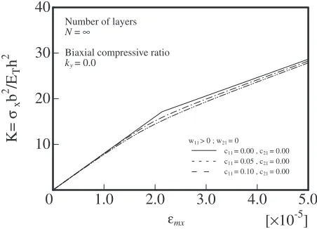
[image:5.595.57.281.69.234.2]The relationship between the non-dimensional average axial compression K and average axial strain of the x-axis direction¾mxis shown in Figs. 3 to 5.
Figure 3 shows the relationship between K and ¾mx for
=1.0 whenky(=Ny/Nx)=0.0, i.e., a biaxial compressive
load ratio corresponding to uniaxial compression. Figures 4 and 5 show the same relationship for biaxial compressive load ratios kyof 0.5 and 1.0, respectively.
Thec11andc21values are the initial deflection amplitudes
of the symmetrical and asymmetrical modes based on eq. (18). Furthermore, c11=0.1 is the one half wave in the
x-direction and the one half wave in the y-direction and indicates that the magnitude is 10% of the plate thickness.
Table 1 lists the variation of the secondary buckling stresses for orthotropic cross-ply laminated plates with initial deflections of c11=0, 0.05 and 0.10 under a biaxial
compressive load ratio of ky=1.0. The analytical method
0.5
1.0
1.5
2.0
2.5
[
×
10
-4]
20
40
60
80
100
0
K=
σx
b
2
/E
T
h
2
Number of layers N=
Biaxial compressive ratio
ky=0.0
ky=0.5
ky=1.0
ε
mx =17.14 (1,1)=11.43 (1,1) =8.57 (1,1)
=89.71(2,2)
=59.81 (2,2)
=44.86 (2,2)
P
K
P
K
P
K
S
K
S
K
S
K
Fig. 2 Relationship between the axial compressive stress K and the average axial shortening ¾mxwithout an initial deflection for N=¨
layers.
1.0
2.0
3.0
4.0
5.0
[
×
10
-5]
10
20
30
40
0
K=
σx
b
2
/E
T
h
2
εmx
Number of layers
N= ∞
Biaxial compressive ratio
ky= 0.0
w11 > 0 ; w21 = 0
c11 = 0.00 , c21 = 0.00
c11 = 0.05 , c21 = 0.00
c11 = 0.10 , c21 = 0.00
Fig. 3 Relationship between the axial compressive stress and average axial shortening with an initial deflection forN=¨layers andky=0.0.
1.0
2.0
3.0
4.0
5.0
[
×
10
-5]
10
20
30
40
0
K=
σx
b
2
/E
T
h
2
εmx
Number of layers
N= ∞
Biaxial compressive ratio
ky= 0.5
w11 > 0; w21 = 0
c11 = 0.00 , c21 = 0.00
c11 = 0.05 , c21 = 0.00
c11 = 0.10 , c21 = 0.00
Fig. 4 Relationship between the axial compressive stress and average axial shortening with an initial deflection forN=¨andky=0.5.
1.0
2.0
3.0
4.0
5.0
[
×
10
-5]
10
20
30
40
0
K=
σx
b
2
/E
T
h
2
εmx
Number of layers
N= ∞
Biaxial compressive ratio
ky= 1.0
w11 > 0; w21 = 0
c11 = 0.00 , c21 = 0.00
c11 = 0.05 , c21 = 0.00
c11 = 0.10 , c21 = 0.00
[image:5.595.314.540.72.235.2] [image:5.595.314.540.284.449.2] [image:5.595.313.541.499.665.2]indicated that the second variation of the total potential energy¤2¬depends strongly on the number of half wavesp
andqin the infinitesimal virtual displacement; the minimum values are then the secondary buckling stress.
Tables 24 list the secondary buckling stresses and number of half waves of infinitesimal virtual displacements p andq
for outer lamination angles of ª=0 and 90° and 3 or 5 layers, as well as those for an infinite number of layers (orthotropic lamination), for initial deflections of c11=0,
0.05 and 0.10 and c21=0, 0.05 and 0.10. Table 2 lists the
results forky=0.0 and Tables 3 and 4 are those forky=0.5
and 1.0, respectively.
As shown in Table 2, for an outer lamination angle of ª=0° and 3 layers,w11 governs the conditions regarding the
deflection pattern of the post-buckling. The one half-wave number of the primary buckling in thex- andy-direction are
determined. Thus, in this case, w21 is ignored. In contrast, for an outer lamination angle of ª=90° and 3 layers, w21
governs the conditions. The two half-wave number of primary buckling in the x-direction and one half-wave number of primary buckling in the y-direction are deter-mined. Thus, in this casew11 is ignored.
As seen in the tables, minimum values ofKsare obtained
[image:6.595.301.549.103.345.2]when infinitesimal virtual displacements are considered regardless of the amplitude of the initial deflection.
Table 1 The variation of the secondary buckling stresses for various deflection patterns andN=¨layers at a biaxial compressive load ratio ofky=1.0.
q c11 c21
p
1 2 3 4
1
0.00 0.00 Stable Stable Stable Stable 0.05 0.00 Stable Stable Stable Stable 0.10 0.00 Stable Stable Stable Stable
2
0.00 0.00 Stable 44.86 72.55 120.59 0.05 0.00 Stable 44.93 72.58 120.61 0.10 0.00 Stable 45.02 72.62 120.62
3
[image:6.595.46.292.104.265.2]0.00 0.00 Stable 72.55 86.05 122.49 0.05 0.00 Stable 72.58 86.07 122.50 0.10 0.00 Stable 72.62 86.09 122.52
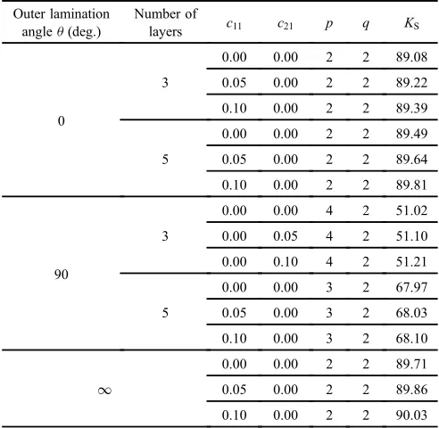
Table 2 Secondary buckling stresses of cross-ply laminated plates for different initial deflection amplitudes, outer lamination angles and number of layers at a biaxial compressive load ratio ofky=0.0.
Outer lamination angleª(deg.)
Number of
layers c11 c21 p q KS
0
3
0.00 0.00 2 2 89.08 0.05 0.00 2 2 89.22 0.10 0.00 2 2 89.39
5
0.00 0.00 2 2 89.49 0.05 0.00 2 2 89.64 0.10 0.00 2 2 89.81
90
3
0.00 0.00 4 2 51.02 0.00 0.05 4 2 51.10 0.00 0.10 4 2 51.21
5
0.00 0.00 3 2 67.97 0.05 0.00 3 2 68.03 0.10 0.00 3 2 68.10
¨
0.00 0.00 2 2 89.71 0.05 0.00 2 2 89.86 0.10 0.00 2 2 90.03
Table 3 Secondary buckling stresses of cross-ply laminated plates for different initial deflection amplitudes, outer lamination angles and number of layers at a biaxial compressive load ratio ofky=0.5.
Outer lamination angleª(deg.)
Number of
layers c11 c21 p q KS
0
3
0.00 0.00 2 3 57.57 0.05 0.00 2 3 57.64 0.10 0.00 2 3 57.71
5
0.00 0.00 2 2 59.66 0.05 0.00 2 2 59.76 0.10 0.00 2 2 59.87
90
3
0.00 0.00 4 2 45.35 0.00 0.05 4 2 45.43 0.00 0.10 4 2 45.52
5
0.00 0.00 3 2 57.53 0.05 0.00 3 2 57.58 0.10 0.00 3 2 57.63
¨
[image:6.595.46.292.327.567.2]0.00 0.00 2 2 59.81 0.05 0.00 2 2 59.91 0.10 0.00 2 2 60.02
Table 4 Secondary buckling stresses of cross-ply laminated plates for different initial deflection amplitudes, outer lamination angles and number of layers at a biaxial compressive load ratio ofky=1.0.
Outer lamination angleª(deg.)
Number of
layers c11 c21 p q KS
0
3
0.00 0.00 2 3 36.42 0.05 0.00 2 3 36.47 0.10 0.00 2 3 36.52
5
0.00 0.00 2 2 44.74 0.05 0.00 2 2 44.82 0.10 0.00 2 2 44.90
90
3
0.00 0.00 3 2 36.42 0.05 0.00 3 2 36.47 0.10 0.00 3 2 36.52
5
0.00 0.00 2 2 44.74 0.05 0.00 2 2 44.82 0.10 0.00 2 2 44.90
¨
[image:6.595.304.549.408.651.2]The post-buckled equilibrium state with small-wave modes
pandq(in both thex- andy-directions) cannot be proved to be unstable by using an infinitesimal virtual displacement.
It can be proved that the post-buckled equilibrium state becomes unstable when almost infinitesimal virtual displace-ments p and q are considered and the inevitable secondary buckling is given analytically.
As shown in Figs. 25 and Tables 24, the secondary buckling stress was several times that of the primary buckling stress; the stresses were obtained for the load-carrying capacity of thin laminated plates after primary buckling. The curves in Figs. 25 become straight lines with a slope equal to that prior to buckling. After primary buckling, the slope of this line may decrease. This indicates a loss of stiffness in the post-buckling range and is greatly dependent on the number of half-wave of the infinitesimal virtual displacementsp andq.5)
It is seen from Tables 24 that the secondary bucklingKs
increases as the number of layers increases. There is a difference in the increasing rates of the secondary buckling as a function of the number of layers between the outer lamination angles of 0 and 90°. The secondary buckling values for outer lamination angles of 0 and 90° agree for an infinite number of layers.
The secondary buckling also decreases with increasing biaxial compressive load ratios, and there was little change in the secondary buckling stress within the ranges of initial deflection amplitudes considered here. In addition, the secondary buckling stresses with an initial deflection were nearly the same as those without any initial deflection, and the secondary buckling Ks increased only slightly as the
amplitude of the initial deflection increased. Accordingly, the initial deflection was 10%of the plate thickness; the effect on the secondary buckling stresses was negligible.
4. Conclusions
We have shown analytically that the post-buckling equi-librium states for simply supported cross-ply laminated plates with initial deflections under biaxial compressive loads can be unstable. We proposed a method based on the secondary variation of the total potential energy to evaluate the stability of the post-buckling equilibrium states, and the secondary buckling was derived. The effect of initial deflections and biaxial compressive load ratios on the post-buckling equi-librium states and secondary buckling stresses were discussed.
Acknowledgments
Financial assistance, the use of apparatus and the receipt of research funding and so on, should all be acknowledged in this section.
REFERENCES
1) G. J. Turvey and I. H. Marshall (eds.):Buckling and Postbuckling of Composite Plates, (Chapman & Hall, London, 1995).
2) F. Bloom and D. Coffin: Handbook of Thin Plate Buckling and Postbuckling, (Chapman & Hall, London, 2001).
3) M. Stein:AIAA J.21(1983) 17291735.
4) M. Uemura and O.-I. Byon:Int. J. Non-Linear Mech.12(1977) 355 370.
5) H. Kasuya, A. Minobe and K. Nemoto:Trans. Jpn. Soc. Mech. Eng.58
(1992) 15441549.
6) H. Kasuya and A. Minobe:J. Soc. Mater. Sci. Jpn.42(1993) 804810.
7) H. Kasuya and S. Tsunoi: Mater. Sci. Res. Int.2(1996) 99104. 8) K. Nemoto, M. Tsujimoto and H. Kasuya: Proc. Sch. Eng. Tokai Univ.
46(2006) 9398.
9) R. M. Jones:Mechanics of Composite Materials, (McGraw-Hill, New York, 1975) Chap. 4.