Surface Modification of SUS304 Stainless Steel Using Carbon Push-Ahead Effect
by Low Temperature Plasma Nitriding
Masato Tsujikawa
1, Daisuke Yoshida
1;, Naohiko Yamauchi
2, Nobuhiro Ueda
2and Takumi Sone
21
Graduate School of Engineering, Osaka Prefecture University, Sakai 599-8531, Japan
2Technology Research Institute of Osaka Prefecture, Izumi 594-1157, Japan
Low temperature nitriding can harden the steel surface. However, the consequent thickness is limited because it depends on the formation of non-equilibrium phase at low temperature diffusion treatment. The hardness drops abruptly at the interface between the treated layer and the substrate as a result of nitriding. In this paper, duplex surface layers produced by combinations of carburizing and nitriding were developed using the carbon push-ahead effect of nitriding using relatively low-temperature plasma treatment. The location of the low-temperature carburized layer was pushed ahead following nitriding to form a support layer for a hard nitrided surface layer. The treatment combination was optimized for a thicker hard layer with good corrosion resistance.
(Received November 8, 2004; Accepted February 21, 2005; Published April 15, 2005)
Keywords: austenitic stainless steel, surface improvement, plasma nitriding, carburizing, corrosion resistance
1. Introduction
Low temperature plasma nitriding can harden the surfaces of austenitic stainless steels without degrading corrosion resistance. It does so by formation of a non-equilibrium precipitation free layer: the so called ‘‘S phase’’ or ‘‘expanded austenite’’. Despite its very high nitrogen content, the S phase has no chromium nitrides that consume the dissolved chromium.1–4)
However, it is difficult to produce a thicker precipitation-free S phase layer. A high temperature and long time treatment should not be applied to suppress formation of chromium nitrides.5)Furthermore, as a characteristic feature
of nitrided steels, the hardness profile of the treated steel shows a steep change in hardness at the border separating the nitrided layer and the substrate.5) Such a change in
mechanical properties would be gentler if we inserted a layer of intermediate hardness underneath the thin hard S phase layer.
Low-temperature plasma carburizing of austenitic stain-less steels also forms a hard and precipitation-free surface layer. The carburized S phase has a thicker case, more moderate hardness distribution, and lower layer hardness than the nitrided S phase does.6,7)
The dissolved carbon is pushed ahead by the incoming nitrogen, thereby accumulating beyond the nitrided layer by low temperature nitriding.4,8–11) Such carbon accumulation
has also been reported to result from simultaneous nitriding and carburizing.12)The authors have also clarified that low
temperature carburized layers are pushed-ahead by low temperature nitriding. Sequential carburizing and nitriding produce clear duplex surface layers.13)
The flexibility of design for an austenitic stainless steel surface layer would be wider if we were able to control the location of the carburized layer using this carbon push-ahead effect by nitriding. This study seeks to determine the optimum surface structure by controlling the microstructure using various combinations of carburizing and nitriding. Corrosion and wear resistance of these combination-treated samples were evaluated respectively using saltwater immer-sion test and dry slide friction test.
2. Experimental Procedure
The material used in this study is an austenitic stainless steel that satisfies the JIS SUS304 grade. Table 1 lists the steel’s chemical composition. Specimen plates were solution-treated at 1303 K for 2.7 ks. Then they were dry ground slightly to the specimen shape of 25 mm width, 50 mm length, and 5 mm thickness. These preparations gave the specimens a fully austenitic structure, as confirmed by X-ray diffraction analysis.
Plasma treatments were performed individually with a laboratory-size apparatus with a simple DC power source. Each specimen, attached with a thermocouple, was set in the furnace as a cathode. After evacuation to1:3310 1Pa, the mixed gas pressure for each specimen was adjusted to 6:67102Pa. Subsequently, specimens were heated to 673 K by the plasma bombardment. Total respective processing time was set as 28.8 ks (8 h) as a constant.
Table 2 shows details of respective plasma treatments along with specimen symbols. For example, the 8
.
N speci-men was plasma treated at 673 K with a mixture of 80% nitrogen gas and 20% hydrogen gas for 8 h. The 8(C+N) specimen was treated by plasma carbo-nitriding process for 8 h at 673 K with a mixture of nitrogen, methane, and hydrogen gas. Similarly, the 4C–4N specimen was first treated by plasma carburizing for 4 h at 673 K, then secondarily treated by plasma nitriding for 4 h at 673 K. In such a sequential process, the gas mixture changes were carried out within 10 s without any temperature change. After plasma treatment, specimens were allowed to cool in the evacuated apparatus. [image:1.595.304.551.316.343.2]X-ray diffraction analysis (XRD), using Cu-K (40 kV, 150 mA) with a monochrometer, was undertaken to identify the crystal structure of the plasma treated layers. Glow
Table 1 Chemical composition of SUS304 sample (mass%).
C Si Mn P S Ni Cr Mo Cu Fe
0.06 0.4 0.94 0.037 0.003 8.3 18.8 0.21 0.31 Bal.
discharge optical emission spectrometry (GDOES) was used to analyze the elemental depth profiling of the treated surfaces. Hardness profiles of cross sections were measured using a Knoop hardness tester. Raman spectroscopy was also used to analyze the state of carbon at the treated surface. Microstructures and hardness profiles were measured at polished and aqua-regia etched sections.
Tribological properties were evaluated with a ball on a plate-type dry slide tribotester using an 8-mm-diameter ceramic (Si3N4) ball as the mated material. The applied load was constant at 18 N. The coefficient of friction was monitored during the tests. After 4000 iterations of sliding friction, the specimen plate wear loss were measured using profilometry. Corrosion resistance of these specimens was estimated by saltwater immersion testing at room temper-ature with 10% NaCl aqueous solution.
An evaluation for surface cracking was made using Vicker’s hardness indentation at the surface of treated specimens. Specimens were indented using a dynamic ultra-micro-hardness tester (DUH-201S; Shimadzu Corp.) perpendicular to the processed surface. With increasing indentation force, cracks occurred suddenly at specimen surfaces. These threshold indentation forces for cracking were recorded.
3. Results and Discussion
3.1 Characteristics of processed surface layers 3.1.1 Layer morphology and hardness profile
Figure 1 shows cross-sectional views of treated speci-mens. Both 8C and 8
.
N layers exhibit a similar bright appearance resulting from their resistance to the aqua regia that was used to reveal the microstructure. The 8C layer differs from the 8.
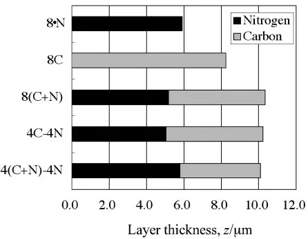
N layer in its features. The interface between the nitrided layer and the substrate is clear. However, the carburized layer presents a more gradual transition with the substrate. The two combined carburized and nitrided specimens, 4C+4N and 4C–4N, have duplex layers irrespective of whether they were processed sequen-tially or simultaneously.Figure 2 depicts the layer thickness as measured from these micrographs. The carburized specimen has a deeper layer than the nitrided specimen. Furthermore, combined processed specimens have deeper layers than the carburized-only specimen. The hard layer thickness of the simulta-neously carburized and nitrided specimen, 8(C+N), was 145% that of the nitrided specimen; the 4C–4N specimen has
a 150% deeper layer than the nitrided-only 8
.
N specimen at an equal processing time. [image:2.595.45.550.84.199.2]The apparent coefficient of carbon diffusion was increased by the combination of nitriding. We require detailed examination to explain this effect, but the following assumption allows a qualitative explanation of the effect. That is, the interstitial sites near the chromium atom are more stable than other sites.14,15) Nitrogen atoms are trapped by sites, because they have more affinity to chromium than Table 2 Plasma process used in this study.
First process Second process Total
Process Symbol Temp. Gas flow ratio (%) Process Temp. Gas flow ratio (%) Process process (K) CH4 N2 H2 Ar time (h) (K) CH4 N2 H2 Ar time (h) time (h)
Nitiriding 8
.
N 673 — 80 20 — 8 — — — — — — 8Carburizing 8C 673 5 — 15 80 8 — — — — — — 8
Simultaneous
8(C+N) 673 5 80 15 — 8 — — — — — — 8
Process
Sequential 4C–4N 673 5 — 15 80 4 673 — 80 20 — 4 8
process 4(C+N)–4N 673 5 80 15 — 4 673 — 80 20 — 4 8
Fig. 1 Cross-section microstructures of plasma-treated SUS304 steels.
[image:2.595.325.526.232.402.2] [image:2.595.316.539.461.634.2]carbon.11,16)Carbon atoms can not remain in these trap sites
because of the occupation by nitrogen. Interstitial atoms in these trap sites need more energy to escape to another sites. Carbon atoms from the surface diffuse only through the ordinary octahedral sites without trapping by chromium. Therefore, the aparent rate of carbon diffusion increases in the conditions with nitrogen.
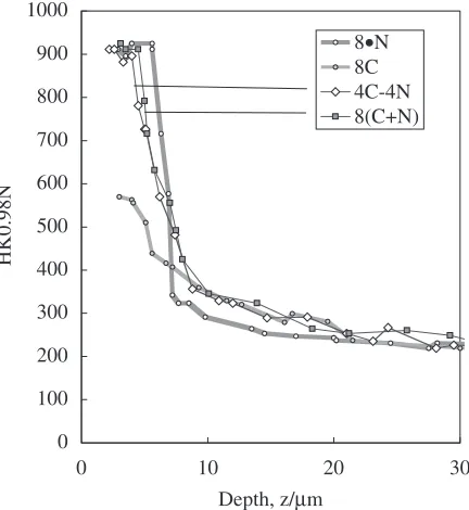
[image:3.595.303.547.72.264.2]Hardness profiles of these four specimens are shown in Fig. 3. The 8C specimen has maximum hardness of about 570 HK, which is far lower than the hardness of other specimens that were concerned with nitriding to a greater or lesser extent. Comparison of the hardness profiles of the 8C specimen with that of the 8
.
N shows that the 8.
N specimen has a hard layer with an abrupt layer-core interface, whereas the carburizing produces a gradually decreasing hardness profile.Two combined carburized and nitrided specimens, 8(C+N) and 4C–4N, show similar hardness profiles. Com-bined processing produces gradually decreased hardness profiles with small bulging at about the 550 HK range even though they have thinner layers of maximum hardness than that of the 8
.
N specimen. The bulging is due to the inner carburized layer pushed-ahead by the presence of nitrogen.3.1.2 Elemental surface profiles
Figure 4 shows elemental depth profiles of plasma-processed specimens. The carbon push-ahead effect of incoming nitrogen13,17) is clearly visible in Figs. 4(a) and
(d). Dissolved carbon is accumulated at the front of the nitrided layer in Fig. 4(a); a large amount of carburized carbon also accumulated beyond the nitrided layer in Fig. 4(d). However, some carbon remains in the nitrided layer of 4C–4N. A small peak of carbon is visible at the sub-surface layer.13)
The simultaneously carburized and nitrided specimen 8(C+N), as shown in Fig. 4(c), displayed high accumulation of carbon beyond the nitrided layer. The carbon
concen-tration at the very surface of this specimen is as high as the carburized-only specimen. Contrary to this, the sequentially carburized and nitrided specimen 4C–4N, as shown in Fig. 4(d), has low carbon concentration at the surface.
3.1.3 X-ray diffraction and raman spectrometry analy-sis
Figure 5 shows XRD patterns of plasma processed speci-mens. The carburized specimen, 8C, and nitrided specimen, 8
.
N, show a typical S phase by carbon and by nitrogen. The X-ray diffraction pattern of 4C–4N is fundamentally the sum of patterns of the nitrided specimen and carburized specimen. Peaks of nitrided S phase (SN) and carburized Sphase (SC)appear separately in the pattern of the 4C–4N specimen. However, in the pattern of 8(C+N), the peaks that were inferred to indicateSphase do not show separate character-istics ofSNandSC. They are positioned betweenSNandSCin
the 8(C+N) pattern. Presence of some chromium carbides was suspected in the 8C and 8(C+N) specimens.
0 100 200 300 400 500 600 700 800 900 1000
0 10 20 30
Depth, z/µm
HK0.98N
8•N 8C 4C-4N 8(C+N)
Fig. 3 Depth profiles of Knoop hardness.
Fig. 4 GDOES elemental profiles of plasma-treated SUS304 steels.
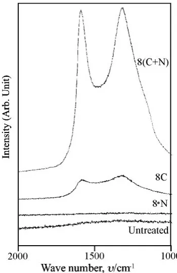
[image:3.595.62.278.74.309.2] [image:3.595.311.540.305.530.2]Hues of plasma-treated surfaces of specimens varied according to their respective processes. Simultaneously combined processes, 8(C+N), engendered the darkest semi-glossed surface of all. The second darkest was the carburized-only specimen surface. The nitrided-carburized-only specimen, 8
.
N, and the sequentially processed specimen, 4C–4N, yielded the brightest surfaces. In Fig. 6, Raman spectroscopy shows a glassy carbon18) at the surface of the simultaneouslyprocessed specimen 8(C+N).
3.2 Wear properties
Figure 7 shows a comparison of wear loss under dry sliding friction. The 8C specimen exhibits substandard wear resistance because of its low maximum hardness. The 4C–4N specimen and the 8
.
N specimen demonstrated excellent wear resistance.On the other hand, the wear of the 8(C+N) specimen proceeded at over twice the rate of the 8
.
N specimen even though its maximum hardness is as high as the 8.
N specimen: a hardness drop at the surface was suspected. The coefficient of friction of the 8(C+N) specimen was 0.4 in the early stage of friction under 150 turns. Other specimens showed a coefficient of friction of 0.7. [image:4.595.79.254.71.341.2]3.3 Corrosion resistance
Table 3 shows results of saltwater immersion test. The nitrided-only specimen, 8
.
N, has excellent corrosion resist-ance, just as untreated SUS304 steel. However, the carbu-rized-only specimen, 8C, showed rust within 72 h. The formation of chromium carbide, as shown in Fig. 5, affects corrosion resistance of the 8C specimen.Saltwater immersion tests indicated a clear distinction between simultaneous processing and sequential processing. Simultaneously carburized and nitrided specimen, 8(C+N), began to form reddish brown rust within 1 h. In contrast, the sequentially carburized and nitrided specimen, 4C–4N, never developed rust. Chromium carbide formation causes this difference.
Figure 4 shows that specimens with poor corrosion resistance have high carbon concentration at the surface. Supersaturated carbon may begin to form carbides over the long duration of plasma processing, even at the relatively low temperature of 673 K.
3.4 Surface material design by combined process of nitriding and carburizing
These results suggest the optimum surface design as a combination of carburizing and nitriding. The process thickens the hard layer by simultaneous nitriding and carburizing as the first process. The surface concentration peak of carbon must be pushed-ahead by the nitriding as a second process for corrosion resistance. The process details are listed in Table 2 as 4(C+N)–4N. This process thickens the nitrogen-S phase by nitriding throughout the process.
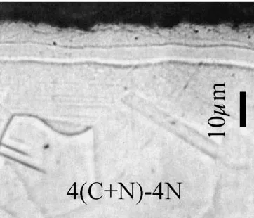
The microstructure and the GDOES profile of 4(C+N)–4N specimen are shown respectively in Fig. 8 and Fig. 9. The duplex layer thickness is greater than 11mm. Carbon concentration at the surface is reduced by the second nitriding process. The hardness profile of this specimen is displayed in Fig. 10. The thickness of the maximum hardness is identical to that of the 8
.
N specimen. Bulging of the intermediate hardness range by carbonS phase is apparent. Corrosion resistance, already listed in Table 3, is as good as the 4C–4N process.Fig. 6 Results of Raman spectrometry for carburized specimens.
[image:4.595.305.549.85.175.2]Fig. 7 Comparison of wear loss under dry sliding condition.
Table 3 Saltwater immersion test result (room temperature).
Specimen Immersion time
8 h 24 h 72 h 240 h
8
.
N8C
8(C+N)
[image:4.595.54.284.605.756.2]3.5 Surface cracking by hardness indentation
Figure 11 shows surface indentation cracking test results. The nitrided-only specimen, 8
.
N, cracked at the smallest indentation force of all. The carburized-only specimen, 8C, did not crack below 2 N. The carburized layer has a higher flexibility than the nitrided layer has because of its moderate hardness and toughness.5)The 8(C+N) specimen and the 4C–4N specimen show greater threshold force than the 8
.
N specimen because the thickness of hard nitrided layers is small and the flexible carburized layer supports them from the back. The critical force of 4(C+N)–4N specimen was low compared to that of 8(C+N) and 4C–4N with thin hard nitrided layers. However, the critical cracking force of the 4(C+N)–4N specimen was slightly better than that of the 8.
N specimen. In consideration of identical thickness of the hard nitrided layers, the result shows the effect of bulging underneath the nitrided layer in the hardness profile.4. Conclusions
The combinations of low temperature nitriding and carburizing processed to 304 type austenitic stainless steel to thicken the case depth and to improve the hardness profile of nitriding. Several conclusions can be drawn concerning surface layer properties.
(1) Plasma-nitriding pushed ahead the plasma-carburized layer. This formed duplex surface layers of different hardness. The total thickness of the case was increased by the combination of carburizing and nitriding. (2) Raman spectroscopy revealed some kind of a glassy
carbon at the surface of a simultaneously carburized and nitrided specimen.
(3) The duplex structure by sequential carburizing and nitriding has excellent corrosion resistance as evaluated by saltwater immersion tests. However, the simulta-neously carburized and nitrided specimen has the poorest corrosion resistance of all.
(4) Simultaneously carburized and nitrided then nitrided specimen showed a thicker maximum hardness layer and the deepest treated layer. This specimen has similar excellent corrosion resistance to that of the sequentially processed specimen.
Fig. 8 Microstructure of the simultaneously carburized and nitrided then nitrided specimen, 4(C+N)–4N.
Fig. 9 GDOES profile of the 4(C+N)–4N specimen.
0 100 200 300 400 500 600 700 800 900 1000
0 10 20 30
Depth, z/µm
HK0.98N
[image:5.595.78.259.72.227.2]8•N 8C 4C-4N 8(C+N) 4(C+N)-4N
Fig. 10 Hardness depth profile of the 4(C+N)–4N specimen.
[image:5.595.323.527.72.173.2] [image:5.595.62.276.292.466.2] [image:5.595.72.267.523.736.2]REFERENCES
1) K. Ichii, K. Fujimura and T. Takase: Netsu Shori25(1985) 191–196. 2) Z. L. Zhang and T. Bell: Surf. Eng.1(1985) 131–136.
3) K.-T. Rie and E. Broszeit: Surf. Coat. Technol.76–77(1995) 425–436. 4) N. Yamauchi, N. Ueda, K. Demizu, A. Okamoto, T. Sone, K. Oku, T. Kouda, K. Ichii and K. Akamatsu: Proc. Int. Current Status Seminar on Thermochemical Surf. Eng. Osaka (2000) 247–261.
5) T. Bell and Y. Sun: Proc. Int. Current Status Seminar on Thermo-chemical Surf. Eng. Osaka (2000) 275–288.
6) Y. Sun, X. Y. Li and T. Bell: Surf. Eng.15(1999) 49–54.
7) Y. Sun, X. Y. Li and T. Bell: Mater. Sci. Technol.15(1999) 1171– 1178.
8) M. P. Fewell, P. Garlick, J. M. Priest, P. T. Burke, N. Dytlewski, K. E. Prince, K. T. Short, R. G. Elliman, H. Timmers, T. D. M. Weijers and B. Gong: Proc. Int. Current Status Seminar on Thermochemical Surf. Eng. Osaka (2000) 177–200.
9) M. J. Baldwin, S. Kumar, J. M. Priest, M. P. Fewell, K. E. Prince and K.
T. Short: Thin Solid Films345(1999) 108–112.
10) X. Li, Y. Sun and T. Bell: Z. Metallkd.90(1999) 901–907. 11) S. Parascandola, W. Mo¨ller and D. L. Williamson: Proc. Int. Current
Status Seminar on Thermochemical Surf. Eng. Osaka (2000) 201–214. 12) C. Blawert, B. L. Mordike, G. A. Collins, K. T. Short, Y. Jiraskova, O. Schneeweiss and V. Perina: Surf. Coat. Technol.128–129(2000) 219– 225.
13) M. Tsujikawa, N. Yamauchi, N. Ueda, T. Sone and Y. Hirose: Surf. Coat. Technol.193/1–3(2004) 309–313.
14) D. L. Douglass, G. Thomas and W. R. Roser: Corrosion20(1964) 15– 28.
15) K. Oda, N. Kondo and K. Shibata: ISIJ Int.30(1990) 625–632. 16) M. Murayama, K. Hono, H. Hirukawa, T. Ohmura and S. Matsuoka:
Scr. Mater.41(1999) 467–473.
17) A. Leyland, D. B. Lewis, P. R. Stevenson and A. Matthews: Surf. Coat. Technol.62(1993) 608–617.