Page 1 of 6 7/20/2015
20XX-01-XXXX
Control Design for PMM-based Generator fed by Active Front-End Rectifier in
More-Electric Aircraft
Mingming Yin, Serhiy Bozhko, and Seang Shen Yeoh
University of NottinghamAbstract
The future aircraft electrical power system is expected to be more efficient, safer, simpler in servicing and easier in maintenance. As a result, many existing hydraulic and pneumatic power driven systems are being replaced by their electrical counterparts. This trend is known as a move towards the More-Electric Aircraft (MEA). As a result, a large number of new electrical loads have been introduced in order to power many primary functions including actuation, de-icing, cabin air-conditioning, and engine start. Therefore electric power generation systems have a key role in supporting this technological trend. Advances in modern power electronics allow the concept of starter/generator (S/G) which enables electrical engine start and power generation using the same electrical machine. This results in substantial improvements in power density and reduced overall weight. One of the potential S/G solutions is to employ a permanent magnet machine (PMM) controlled by active front-end rectifier (AFE). Operation of the PMM as a generator at wide range of speed that is dictated by the engine and electrical loads connected to the aircraft bus require careful design of the controllers. Corresponding plant models are derived and verified with simulations using developed models in Matlab/Simulink. The relevant controllers are designed based on the derived plants and operating points. The controllers are tested with Simulink models and experimentally using a scaled prototype of the investigated generator system.
Key words: permanent magnet generator, flux weakening, control design, DC link voltage, more electric aircraft
Introduction
The present aircraft systems technologies need to have significant changes for the sake of tendency to be more efficient and environmentally-friendly. The More-Electric Aircraft (MEA) is one of the main trends in modern aircraft engineering aiming to replace the conventional aircraft topology [1]. The subsystems that used mechanical, pneumatic, hydraulic power now are to be partially or completely substituted by electrical systems which result in significant increased on-board electric power demand. Hence the role of electrical power generation system is of great importance.
The current electrical power generation system on-board most aircrafts normally employs three-stage wound field synchronous generators. This generator has been extensively adopted in fixed wing and rotor craft applications and has proved to be highly reliable and inherently safe. However, there is a limit of increasing the power density due to electronic components located on the rotor. Additional exciter windings are required for electrical start operation which increases the overall machine weight [3]. Advances in modern power electronic converters make it possible to re-configure the power generation system while considering other machine types such as the
permanent magnet machine (PMM), induction machine (IM), and switched reluctance machine (SR) [2] [5].
In addition, electric engine start function can be incorporated using the machine for starter/generator (S/G) scheme. It is one of the most significant change brought by the MEA concept that offers advantages such as reduction of aircraft empty weight, less maintenance downtime, lower cost and improved reliability [4][6][7][8].
In terms of control strategies for aircraft S/G system, there are several papers reporting on this [9][10][11][12]. Based on variable speed drive application, a control strategy of the doubly fed induction generator is achieved by inner flux control loop and stator-voltage outer loop in [9]. A control methodology which utilizes angle and speed estimation algorithm is presented [10]. The high frequency voltage signal and the subsequent demodulation of high frequency stator current make it possible to achieve sensor-less operation of full-torque from zero speed to ignition speed. Detailed control design of the PMM-based S/G has been studied in [11] and [12]. These papers consider regulation of DC link current during generating mode to accommodate droop control for possible parallel operation of multi-source aircraft power system. Detailed design and analysis of DC link voltage controller that is typically used for stand-alone power systems has yet to be investigated. In addition to that, the stability of FW controller during generator mode still needs to be analyzed to ensure stable operation throughout the generator speed operating range. This paper aims to fill in the gaps for both of these controllers by detailed plant derivation and control design analysis in generator mode. The paper shall cover the control design of the S/G system in generator mode only. More information on starter mode control can be found in [11] and [12].
The paper shall be structured as follows; the investigated generator system and the relevant model equations are introduced. The control structure is formed based on the requirements in generator mode. Next, the control plant for FW and DC link is derived from the equations to aid with the controller design process. They are verified at different operating points with equivalent non-linear models built in Matlab/Simulink environment. The controllers can be designed based on the derived plants and they are tested across the speed operating range in generator mode. Finally, the control design process is validated using a small prototype test rig followed by conclusions and possible future work.
Power System
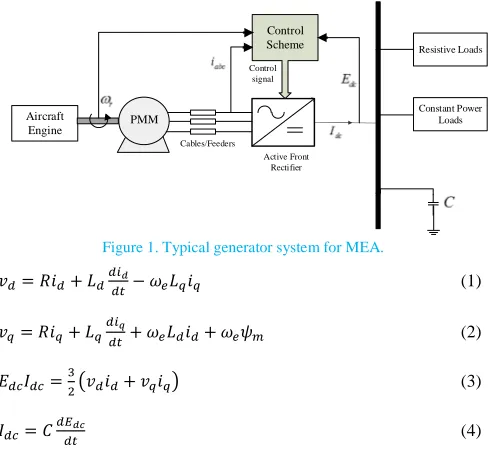
One of the possible topology of MEA generator system that is investigated is shown in Figure1.ωris the rotor speed,Cis the DC
link capacitor, andiabcis the three phase stator currents.EdcandIdcare
connected to the aircraft DC bus. In starter mode, the PMM is driven by the AFE to start the engine using electrical power from the ground power supply or auxiliary power unit (APU). In generating mode, the engine drives the PMM and the generated power is sent to the DC bus to supply onboard loads. They are generally represented as resistive and constant power type loads. The relevant equations (1)-(4) needed to represent the PMM, AFE, and DC bus is introduced to establish the average model of the generator system for control design process.
Aircraft
Engine PMM
Active Front Rectifier
Control Scheme
Control signal
Resistive Loads
Constant Power Loads
[image:2.595.318.549.130.276.2]Cables/Feeders
Figure 1. Typical generator system for MEA.
ݒௗ=ܴ݅ௗ+ܮௗௗௗ௧−߱ܮ݅ (1)
ݒ=ܴ݅+ܮௗௗ௧+߱ܮௗ݅ௗ+߱߰ (2)
ܧௗܫௗ=ଷଶ൫ݒௗ݅ௗ+ݒ݅൯ (3)
ܫௗ=ܥௗாௗ௧ (4)
whereid,q,vd,q, andLd,qare the AC currents, voltages, and inductances
respectively indqframe.Ris the stator resistance,ωeis the electrical
speed, andψmis the machine flux. The parameter values are shown in
Table 1.
Table 1. Parameters of the system.
Parameter Value
Stator resistance,R 1.058mΩ
d-axis inductance,Ld 99µH
q-axis inductance,Lq 99µH
Mutual flux,ψm 0.03644Vs
Combined inertia,J 0.103kgm2
DC link capacitor,C 1.2mF
Pole pairs,p 3
Maximum stator current,im 400A
Nominal DC link voltage,Edcrated 270V
Rated power,Prated 45kW
Generating speed range [20krpm, 32krpm]
Generator Mode Control Scheme
Field oriented vector control is chosen as the control structure for the generator system as shown in Figure 2. Any symbols marked with * are the reference value for the respective control variables.iqlimis the
limit value foriq*andimis the maximum stator current.|V|is the AC
stator voltage magnitude andvabcis the three phase voltages.iabcis
regulated in rotating reference frame (dq) using the inner current controllers. The design of these controllers has been commonly adapted for drive systems. Following the generator mode of operation,
Edc is controlled on the outer loop during generator mode. Flux
weakening (FW) control is also employed to prevent over-modulation
of the AFE when the power system is operating in high speed regions. This is achieved by limiting|V|using de-fluxing current dictated by
id*. The controlled variables are regulated using well known PI based
controllers. A dynamic limiter is present which determines the limit foriq*based onid*andimusing the current limit equation [11]:
݅ =ට݅ଶ−݅ௗଶ (5)
dc E
*
|
|V id*
*
q i |
|V
*
q
v
*
abc
v
d
i
q
i
abc
i
*
dc E
*
d v
2 2 lim m d q i i i
Figure 2. Control scheme of generator system.
In this control structure, the speed of the aircraft turbine is assumed to be controlled externally. Another assumption is made whereby the generator system does not reach saturatediq*(load demand higher than
load supply).
Control Plant
Some of the model equations contain non-linearity that can be linearized before being used for small signal analysis. The small signal models are obtained using Taylor’s series around an operating point and are expressed as follows:
߲ݒௗ=ܴ߲݅ௗ+ܮௗݏ݅ௗ−݅ܮ߲߱−߱ܮ߲݅ (6)
߲ݒ=ܴ߲݅+ܮݏ߲݅+߱ܮௗ߲݅ௗ+߲߱ܮௗ߲݅ௗ+߲߰߱ (7)
߲ܫௗ=ଶாଷబ(ݒௗ߲݅ௗ+݅ௗ߲ݒௗ+ݒ߲݅+߲݅ݒ)߲݅ௗ−ଶாబଷ మ(ݒௗ݅ௗ+
ݒ݅)߲ܧௗ (8)
The linearized voltage limit equation that is used to calculate|V|is shown as [11]:
߲|ܸ| =௩బ
||బ߲ݒௗ+
௩బ
||బ߲ݒ (9)
where the variables with the subscript 0 are obtained around a specified operating point. The closed loop inner current transfer functions are shown as:
ܶܨௗ,(ݏ) =డడ,,∗=൫ଶకఠ,ିோ൯௦ାఠ
మ,
,(௦మାଶకఠ௦ାఠమ) (10)
The following sub-sections will detail the plant derivation forEdc
and FW to aid with the controller design using the relevant linear equations. The respective controllers can then be designed depending on the worst case operating point. For this generator system, that operating point is found to be at 32krpm with full load connected to the DC bus (45kW).
DC Link Voltage Controller Design
In this section, the plant is derived to relate output ∂Edcto input
∂iq*for the DC link controller design process. Using equation (4), (6),
[image:2.595.36.280.166.392.2]Page 3 of 6
߲ܧௗ=ൣଷ൫௩బబା௩ଷாబబబ൯ିଶ௦ா
బమ ൧൦
൫ݒ+൫ܴ+ܮݏ൯݅−ܮ߱݅ௗ൯߲݅ +൫ݒௗ+ (ܴ+ܮௗݏ)݅ௗ+ܮௗ߱݅൯߲݅ௗ
+൫݅(߰+ܮௗ݅ௗ)−݅ௗ݅ܮ൯߲߱
൪ (11)
Assuming that the change of speed is much slower than the electrical dynamics, then for the purpose of control design∂ωecan be assumed
constant. ∂id terms are considered as disturbances and are not
considered as part of the plant. TheEdcplant is derived with addition
of (10) to form:
డா
డ∗=ܶܨ(ݏ)
ଷாబൣ௩బା൫ோା௦൯బିఠబబ൧
ൣଷ൫௩బబା௩బబ൯ିଶ௦ாబమ ൧ (12)
The plant is verified by comparing step response with a non-linear model of the generator system build in Simulink environment. A similar operating point at the highest speed range (32krpm) and full load is selected as an example for both models. Both of the step responses ofEdcare shown in Figure 3. The two lines coincide with
each other which signify that the derived transfer function can be used to represent the desired control plant. At the operating point, equation (12) is shown numerically as:
డா డ∗=
ିସହ(௦ିସ.ସହ×ଵర)(௦ାସସସଽ)
[image:3.595.347.521.74.224.2](௦మା଼଼଼ସ௦ାଷ.ଽସ଼×ଵళ)(௦ାଶ.ଽ) (13)
Figure 3. Open loop step responses to a step input ofiq*= -1A of theEdcplant
(blue) and the non-linear Simulink model (red).
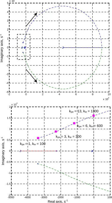
The transfer function is of third order and one of the zeroes (4.45 × 10⁴) is located on the right hand plane (RHP) that can be visualized on a root locus in Figure 4. This indicates a non-minimum phase system that may limit the stability of the controller.
In closed loop configuration together with the PI controller, the root loci shape is similar to the open loop plant. It can be seen that there is a limit range for the closed loop gain in Figure 5. The Edc
proportional,kpe, and integral term,kie, are increased relative to each
other and it can be seen that the conjugate poles of the transfer function tend to move towards the RHP. The stability limit of the controller is when the poles are on the border between the left hand plane (LHP) and RHP. The system becomes unstable once the poles are on the RHP. At this operating point, theEdccontroller stability limit is found to be
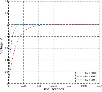
aboutkpe= 13 andkie= 1300. The closed loop step response ofEdccan
be seen in Figure 6 which confirms the controller stability range.kpe=
1 andkie = 100 are selected for the Edc controller which provides
[image:3.595.340.528.267.608.2]satisfactory dynamic response and capability of operating up to the highest speed with full load operating point.
Figure 4. Open loop root locus ofEdcplant operating at 32krpm.
Figure 5. Closed loop root locus with PI (above) and zoomed area (below) showing pole positions at different controller gain values.
0 0.01 0.02 0.03 0.04 0.05
-1 0 1 2 3 4 5 6 7
Linear model Non-linear model
-2 0 2 4 6 8 10
x 104 -5
-4 -3 -2 -1 0 1 2 3 4 5x 10
4
-2 0 2 4 6 8 10
x 104 -5
-4 -3 -2 -1 0 1 2 3 4 5x 10
4
-5000-2 -4000 -3000 -2000 -1000 0 1000
-1.5 -1 -0.5 0 0.5 1 1.5
2x 10
4
kpe= 1, kie= 100
kpe= 3, kie= 300
kpe= 6, kie= 600
kpe= 13, kie= 1300
Gain increases
Real axis, s-1
V
o
lt
a
g
e
,
V
Time, seconds
Im
a
g
in
a
ry
a
x
is
,
s
-1
Real axis, s-1
Im
a
g
in
a
ry
a
x
is
,
s
-1
Im
a
g
in
a
ry
a
x
is
,
s
[image:3.595.56.244.301.466.2]Figure 6. Closed loopEdcstep responses to reference value = 1V for various
kpeandkiecombinations.
Flux Weakening Controller Design
The FW plant is derived specifically in generator mode for controller stability analysis that was designed in starter mode. The FW controller has been designed and its stability analyzed in starter mode [11]. Since the initial speed controller for starter mode is switched to
Edccontroller, the stability aspects may change and could affect the
performance of the FW controller in generator mode. The plant is derived to relate output∂|V|to input∂id*. It is derived using equations
(6), (7), and (9):
߲|ܸ| = ଵ
||బ൦
(߱ܮௗݒ+ܴݒௗ+ܮௗݏݒௗ)߲݅ௗ +൫ܴݒ+ܮݏݒ−߱ܮݒௗ൯߲݅ +൫ܮௗ݅ௗݒ+߰ݒ−ܮ݅ݒௗ൯߲߱
൪ (14)
Similar to equation (11),∂|V|is found to be influenced by∂id*,∂iq*,
and∂ωe. With the assumption of constant∂ωeand∂iq*as disturbances,
the plant is simplified together with (10):
߲|ܸ| =|ଵ|
బܶܨௗ(ݏ)ൣ(߱ܮௗݒ+ܴݒௗ+ܮௗݏݒௗ)൧߲݅ௗ
∗ (15)
The derived FW plant is verified with equivalent non-linear Simulink model in generator mode and good correlation between the step responses is achieved. The transfer function in the same operating point (32krpm under full load) is shown as:
డ||
డ∗=
.ସ଼ଵଶ(௦ାଵ.ହଽ଼×ଵర)(௦ାସସସଽ)
(௦మା଼଼଼ସ௦ାଷ.ଽସ଼×ଵళ) (16)
All of the poles and zeroes of the FW plant are on the LHP which shows minimum phase characteristics. Analysis reported in [11] and [12] showed non-minimum phase nature during operation in starter mode. This change would mean that the controller stability range for FW increases when operating in generator mode. Using a pure integral controller, the closed loop root locus is shown in Figure 7. As the controller gain increases, the conjugate poles moves towards the LHP.
The step response with different FW controller integral gain,kiv, is
shown in Figure 8. The response whenkiv= 1500 is satisfactory during
[image:4.595.342.520.115.276.2]operation in generator mode and it is selected for the FW controller.
Figure 7. Closed loop root locus with pure integral controller showing pole positions at different gain values.
Figure 8. Closed loop|V|step responses to reference value = 1V for different
kiv.
Results and Discussion
Time domain simulation
The designed controllers are tested in simulation with the non-linear Simulink model. The relevant control parameters are shown in Table 2.
Table 2. Parameters of the control scheme.
Parameter Value
Inner current loop controller proportional term,kpc 0.87
Inner current loop controller integral term,kic 3908
OuterEdcloop reference value,Edc* 270V
Outer FW loop reference value,|V|* 156V
Maximum current load at 45kW,iL 170A
0 0.005 0.01 0.015 0.02 0.025 0.03 0.035 0.04 -0.5
0 0.5 1 1.5 2
kpe = 13, kie = 1300 kpe = 6, kie = 600 kpe = 3, kie = 300 kpe = 1, kie = 100
-3.5 -3 -2.5 -2 -1.5 -1 -0.5 0 0.5
x 104 -1.5
-1 -0.5 0 0.5 1 1.5x 10
4
0 0.005 0.01 0.015 0.02 0.025 0.03
0 0.2 0.4 0.6 0.8 1 1.2 1.4
kiv = 5000 kiv = 1500 kiv = 500 Time, seconds
V
o
lt
a
g
e
,
V
kiv= 1
kiv= 1500
kiv= 10000
Real axis, s-1
Im
a
g
in
a
ry
a
x
is
,
s
-1
Time, seconds
V
o
lt
a
g
e
,
[image:4.595.346.524.319.479.2] [image:4.595.330.545.616.713.2]Page 5 of 6
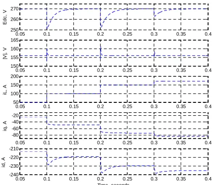
Figure 9 shows the responses when operating in generator mode with the designed controllers. The generator system is subjected to loads at intervals of 0.1s that accumulates to the full load current capacity (170A based on 45kW at 270VDC bus voltage). At each load impact,
Edcand|V|are regulated back to their reference values.id,qis adjusted
accordingly to supply sufficient power for the loads and to maintain
|V| within the limits.iq is seen as negative to denote power flow
moving to the DC bus in the generator system. This shows that the designed controllers are able to work properly even at the highest operating speed and load for this generator system.
Figure 9. Responses of key variables to electrical loads,iL, = 100A, 150A, and
170A att= 0.1s, 0.2s, and 0.3s respectively.
Experimental Results
A small scale experimental rig is built that consists of a 2.5kW PMM and a 4.8kW DC machine with their respective drives seen in Figure 10. The DC machine fulfills the role of the aircraft engine to provide load torque for both starter and generator modes. The PMM is driven by a two-level PWM converter at 12.5kHz and is controlled by a DSP/FPGA control platform. The control performance of this test bench in generator mode is analyzed to validate the control design process in this paper.
The key parameters of this test bench and controllers are recorded in the Appendix. The controllers are redesigned to be compatible with the test bench parameters. The inner current loop controllers are designed to achieve 300Hz bandwidth while the outer loop controller gains are selected based on the worst case operating point (4krpm with 5A DC load).
Figure 11 shows the steady state responses of the key control variables during generator mode operation at 3.6krpm. At approximately t = 0.37s, the initial resistive load of 320Ω is disconnected from the DC bus.Edcand|V|are regulated back to their
reference values even after the load disconnection. The controllers respond satisfactorily in the event of load changes.
[image:5.595.50.266.183.370.2]Figure 10. Experimental test bench.
Figure 11. Controlled variable responses when operating at 3.6krpm with unloading att= 0.37s.
Conclusion
The control design of a MEA generator system based on a PMM fed by AFE was investigated in this paper. FW andEdccontrol were
considered to meet the performance requirements in generator mode. The control scheme was formed based on the control requirements. Their respective control plants were derived with appropriate assumptions for small signal analysis. These plants were verified with equivalent non-linear models built in Matlab/Simulink around a fixed operating point. The Edc plant exhibited non-minimum phase
characteristics; a positive zero located on the root locus LHP. Its corresponding controller has to be carefully designed as there is a limited stability gain range. The FW plant was found to be minimum phase in generator mode compared to non-minimum phase during motoring mode reported in previous publications. This would mean that the controller has more stability range when operating in generator mode. The controllers were designed based on the worst case operating point to allow stable control throughout the speed and load operating range. The performance of the designed controllers was tested in time domain simulation with the non-linear Simulink model. An experimental test bench was also constructed to verify the control design process. Both sets of results showed successful control performance even when operating close to the worst case operating point.
0.05 0.1 0.15 0.2 0.25 0.3 0.35 0.4
250 260 270
E
d
c
,
V
0.05 0.1 0.15 0.2 0.25 0.3 0.35 0.4
150 155 160 165
|V
|,
V
0.05 0.1 0.15 0.2 0.25 0.3 0.35 0.4
50 100 150 200
iL
,
A
0.05 0.1 0.15 0.2 0.25 0.3 0.35 0.4
-80 -60 -40 -20
iq
,
A
0.05 0.1 0.15 0.2 0.25 0.3 0.35 0.4
-240 -230 -220 -210
Time, seconds
id
,
A
0 0.1 0.2 0.3 0.4 0.5 0.6 0.7 0.8 0.9 1 590
600 610
E
d
c
,
V
0 0.1 0.2 0.3 0.4 0.5 0.6 0.7 0.8 0.9 1 200
250 300
|V
|,
V
0 0.1 0.2 0.3 0.4 0.5 0.6 0.7 0.8 0.9 1 -4
-2 0
id
,
A
0 0.1 0.2 0.3 0.4 0.5 0.6 0.7 0.8 0.9 1 -5
0 5
Time, seconds
iq
,
A
Edc Edc*
|V| |V|*
id
iq
DC Drive
DC Machine PMM
[image:5.595.327.540.279.434.2]References
[1] A. AbdElhafez., A. J. Forsyth. A Review of More-Electric Aircraft AEROSPACE SCIENCES & AVIATION TECHNOLOGY,ASAT- 13, May 26 – 28, 2009
[2] MITCHAM A.J., CULLEN J.J.A.: ‘Permanent magnet generator options for the more electric aircraft’. Int. Conf. on Power Electronics, Machines and Drives, (Conf. Publ. No. 487), June 2002, pp. 241–245
[3] Patrick W Wheeler, Jon C Clare, Andrew Trentin, Serhiy Bozhko, “An overview of the more electrical aircraft”, Proceedings of the Institution of Mechanical Engineers Part G Journal of Aerospace Engineering, 2012, 227(4):578-585 [4] Serhiy Bozhko, Seang Shen Yeoh, Fei Gao, Christopher Hill,
“Aircraft Starter-Generator System based on Permanent-Magnet Machine fed by Active Front-End Rectifier” Department of Electrical and Electronic Engineering, University of Nottingham, United Kingdom
[5] F. Gao, S. Bozhko, Y. S. Shen, and G. Asher, “Control design for PMM starter-generator operated in flux-weakening mode”, 48th Power Engineering Conference (UPEC), Dublin, September 2013.
[6] A. Abdel-Hafez, Power Generation and Distribution System for a More Electric Aircraft - A Review,Recent Advances in Aircraft Technology, 2012.
[7] K. Emadi and M. Ehsani, "Aircraft power systems: technology, state of the art, and future trends,"Aerospace and Electronic Systems Magazine, IEEE, vol. 15, pp. 28-32, 2000.
[8] W. Shanshan and L. Yongdong, "Application and challenges of power electronics for variable frequency electric power system of more electric aircraft," in Electrical Machines and Systems (ICEMS), 2011 International Conference on, 2011, pp. 1-4. [9] F. Khatounian ; E. Monmasson ; F. Berthereau ; E. Delaleau;
J.P.Louis, “Control of a Doubly Fed Induction Generator for Aircraft Application”, Industrial Electronics Society, 2003. IECON '03. The 29th Annual Conference of the IEEE
[10] Antonio Griffo; David Drury; Tadashi Sawata; Senior Member; IEEE and Phil H.Mellor, “Sensorless starting of a wound-field synchronous starter/generator for aircraft applications”, IEEE
TRANSACTIONS OF INDUSTRIAIL
ELECTRONICS,VOL.59,NO.9,SEPTEMBER 2012
[11] S. S. Yeoh, F. Gao, S. Bozhko, G. Asher, “Control design for PMM-based starter generator system for More Electric Aircraft”, Power Electronics and Applications (EPE'14-ECCE Europe), 2014 16th European Conference on, Publication Year: 2014 , Page(s): 1 – 10
[12] S. Bozhko, S. S. Yeoh, F. Gao, T. Yang, C.Hill, “Control Design for Electric Starter-Generator Based on a High-Speed Permanent-Magnet Machine Fed by an Active Front-End Rectifier”, SAE Technical Paper 2014-01-2139.
Appendix
Test bench and control parameters:
Parameter Value
Stator resistance,R 1.2Ω
d-axis inductance,Ld 6.17mH
q-axis inductance,Lq 8.379mH
Mutual flux,ψm 0.23Vs
Combined inertia,J 0.0116kgm2
Mechanical friction,fc 0.5372Nm
DC link capacitor,C 4.7mF
Maximum stator current,im 8A
Parameter Value
idloop controller proportional term,kpd 13.8
idloop controller integral term,kid 9470
iqloop controller proportional term,kpq 18.7
iqloop controller integral term,kiq 12543
Edcloop controller proportional term,kpe 0.1
Edcloop controller integral term,kie 100
FW loop controller integral term,kiv 100
Edcreference value,Edc* 600V