1876-6102 © 2017 The Authors. Published by Elsevier Ltd. This is an open access article under the CC BY-NC-ND license (http://creativecommons.org/licenses/by-nc-nd/4.0/).
Peer-review under responsibility of the scientific committee of the 8th International Conference on Applied Energy. doi: 10.1016/j.egypro.2017.03.556
Energy Procedia 105 ( 2017 ) 1895 – 1901
ScienceDirect
The 8
thInternational Conference on Applied Energy
–
ICAE2016
Further improvement of fluidized bed models by
incorporating zone method with Aspen Plus interface
Yukun Hu
a,*, Jihong Wang
a, CK Tan
b, Chenggong Sun
c, Hao Liu
ca
School of Engineering, University of Warwick, Coventry CV4 7AL, UK
b
Faculty of Computing, Engineering and Science, University of South Wales, Pontypridd CF37 1DL, UK
c
Faculty of Engineering, University of Nottingham, Nottingham NG7 2RD, UK
Abstract
While providing a fast and accurate tool of simulating fluidized beds, the major limitation of classical zero-dimensional ideal reactor models used in process simulators, such as models built into commercial software (e.g. Aspen Plus®), has
been the difficulties of involving thermal reciprocity between each reactor model and incorporating heat absorption by the water wall and super-heaters which is usually specified as model inputs rather than predicted by the models themselves. This aspect is of particular importance to the geometry design and evaluation of operating conditions and flexibility of fluidized beds. This paper proposes a novel modelling approach to resolve this limitation by incorporating an external model that marries the advantages of zone method and Aspen Plus in a robust manner. The improved model has a relatively modest computing demand and hence may be incorporated feasibly into dynamic simulations of a whole power plant.
© 2016 The Authors. Published by Elsevier Ltd.
Selection and/or peer-review under responsibility of ICAE
Keywords: zone method; Aspen Plus; fluidized beds; process simulation; radiation analysis
1.Introduction
Circulating Fluidized Bed (CFB) technology has been developed and served as effective method for burning solid fuels for many industrial applications since the 1980s, such as coal combustion, due to its inherent advantages over conventional combustion method like fuel flexibility, high combustion intensity, and low emissions [1]. Although technical knowledge about the design and operation of CFB is widely available for pilot plant and large scale units [2], few have conducted modelling of the whole CFB power plant and hence little is known about its dynamic performance and operational flexibility [3]. This might be due to the fact that the combustion process occurring in a CFB boiler involves complex phenomena like
* Corresponding author. Tel.: +44 (0)24 765 22333; E-mail address: [email protected] (Y. Hu)
© 2017 The Authors. Published by Elsevier Ltd. This is an open access article under the CC BY-NC-ND license (http://creativecommons.org/licenses/by-nc-nd/4.0/).
chemical reactions, heat and mass transfer, particle reduction due to combustion and it may also lie in the shortage of effective modelling approaches.
Nomenclature
Abbreviations
ABFBC Atmospheric Bubbling Fluidized-Bed Combustor
CFB Circulating Fluidized Bed
CPFD Computational Particle Fluid Dynamics
DFAs Directed Flux Areas
MCRT Monte-Carlo based Ray-Tracing
TEAs Total Exchange Areas Symbols
Ai area of the i-th surface zone m2
ܩ
నܩ
ǡ
രሬሬሬሬሬሬሬሬ ܩ
രሬሬሬሬሬሬሬǡ ܵ
నܵ
രሬሬሬሬሬሬሬǡ ܵ
నܩ
രሬሬሬሬሬሬ
నܵ
directed flux areas m2Ki extinction coefficient of gas zone i m-1
ṁ mass flow rate kg s-1
ݍሶୡ୭୬୴ǡ୧ heat convection term of surface zone i W m-2
ܳሶୡ୭୬୴ǡ୧ heat convection term of gas zone i W
ܳሶୣ୬୲୦ǡ୧ enthalpy transport term of gas zone i W
ܳሶୱǡ୧ net radiation from the surface zone i W
ܳሶǡ୧ net radiation absorbed by the gas zone i W
Tg,i or j temperature of gas zone i or j K
Ts, i or j temperature of surface zone i or j K
Vi volume of gas zone i m3
σ Stefan-Boltzmann constant (5.6687×10⁻⁸) W m-2 K-4
CFB modelling has been implemented using commercial software for a long time, such as Aspen Plus®
[4-7] and Computational Particle Fluid Dynamics (CPFD)® [8-9]. Although the advancement in Aspen Plus
has made time-dependent dynamic simulation, prediction and control of CFB combustion processes in real time possible, the major limitation is that classical zero-dimensional ideal reactor models used in Aspen Plus has been the difficulties of involving thermal reciprocity between each reactor model and incorporating heat absorption by the water wall and super-heaters which is usually specified as model inputs rather than predicted by the models themselves. This aspect is of particular importance to the geometry design and the evaluation of operating conditions and flexibility of fluidized beds. On the other hand, although CPFD is widely used to simulate combustion systems and can predict the detailed local heat and mass transfer information available for the entire computational domain, it often takes several days if not weeks to provide useful results for large industrial cases. Therefore, CPFD models are unlikely for being incorporated into dynamic simulations and used to study the starting up and shutting down a plant, changes of conditions during a reaction, holdups, thermal changes and more.
expected to have a relatively modest computing demand and hence feasible to be incorporated into dynamic simulations of a whole CFB power plant.
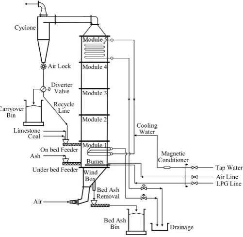
2.Modelling object
A 0.3MW Atmospheric Bubbling Fluidized-Bed Combustor (ABFBC) test rig is used as the simulation object in this work, as shown in Figure 1 [12]. The main body of the test rig is the modular combustor formed by five modules of internal cross section of 0.45×0.45 m and 1 m height. The inner walls of the modules are refractory lined and insulated. The first and fifth modules refer to the bed and cooler, respectively, and the ones between them are the freeboard modules. There exist two cooling surfaces in the
modular combustor, as shown in Figure 1, providing 0.35 m2 and 4.3 m2 of cooling surfaces, respectively.
Cyclone
Air Lock
Diverter Valve
Recycle Line Carryover
Bin
Limestone Coal
Ash
Air
Under bed Feeder On bed Feeder
Bed Ash Removal
Cooling Water
Magnetic Conditioner
Bed Ash
Bin Drainage
Tap Water Air Line LPG Line Wind
[image:3.544.145.396.218.462.2]Box Burner Module 1 Module 2 Module 3 Module 4 Module 5
Fig. 1. Schematic of the 0.3 MW ABFBC test rig
3.Modelling approaches
The previous work of Sotudeh-Gharehaagh et al. [4] had described in details the implementation of Aspen Plus reactor modules [13] for CFB modelling and hence need not to be repeated here. This paper mainly focuses on the further improvement of the fluidized bed models within the framework of Aspen Plus by incorporating a rigorous radiation sub-model based on the zone method of radiation analysis.
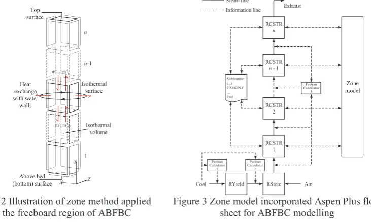
fluidized bed. However, even more complicated zoning arrangement and flow pattern are also possible, see [14], which depend on the requirements of a specific problem. An energy balance is formulated for each zone taking into account radiation interchange between all volume and surface zones, the enthalpy transport, and the source term associated with convection [15]. Figure 3 shows the zone model incorporated Aspen Plus flow sheet for ABFBC modelling. RYield (Aspen Plus reactor) is used to model the devolatilization process by specifying the yield distribution vector via an In-Line Fortran Calculator 1 (Aspen Plus calculator block) according to the coal ultimate analysis; RStoic (Aspen Plus reactor) is used to model volatile combustion process by specifying the fractional conversion of key components via an In-Line Fortran Calculator 2; the mean axial voidage in a certain interval between different heights of the combustor is calculated via an In-Line Fortran Calculator 3; char combustion above bed is implemented using a set of RCSTRs (1 to 6 in this case, Aspen Plus reactor) with the user defined kinetics – USRKIN.f (Aspen Plus Subroutine). In the simulation, the RCSTR block temperatures are recalculated by the zone model based on the retrieved enthalpy flows at each iteration to get a new value as the initial value at the next iteration until the convergent tolerance is satisfied.
1 n-1 n ṁ+ i-1 ṁ -i ṁ+ i ṁ -i+1 Y Z X Above bed (bottom) surface Top surface Isothermal surface Isothermal volume Heat exchange with water walls Air RYield RStoic RCSTR 1 RCSTR 2 RCSTR
[image:4.544.90.456.247.466.2]n - 1 RCSTR n Subroutine: (...) USRKIN.f … End Fortran Calculator 2 Fortran Calculator 1 Coal Fortran Calculator 3 Exhaust Steam line Information line Zone model
Figure 2 Illustration of zone method applied in the freeboard region of ABFBC
Figure 3 Zone model incorporated Aspen Plus flow sheet for ABFBC modelling
The radiation term in the energy balance equations is written in terms of exchange factors known as Directed Flux Areas (DFAs) (denoted by ܩരሬሬሬሬሬሬሬሬ ܩనܩǡരሬሬሬሬሬሬሬǡ ܵనܵ രሬሬሬሬሬሬሬǡ ܵనܩ രሬሬሬሬሬሬనܵfor gas-gas, gas-surface, surface-gas, and surface-surface exchange respectively in Eqs. 1 and 2). The energy balances on all zones yield a set of simultaneous non-linear equations which can be solved to determine the temperature and heat flux at each zone.
For a system of N volume zones and M surface zones, the following energy balances can be written.
ܳሶǡ୧ൌ ܩരሬሬሬሬሬሬሬሬɐܶܩ ǡ୨ସ ே
୨ୀଵ
ܩരሬሬሬሬሬሬሬሬܵ ெ
୨ୀଵ
ߪܶୱǡ୨ସെ Ͷܭ୧ܸ୧ߪܶǡ୧ସ െ ܳሶୡ୭୬୴ǡ୧ ܳሶୣ୬୲୦ǡ୧ǡ (Eq. 1)
ܳሶୱǡ୧ൌ ܵരሬሬሬሬሬሬሬɐܶ݅ܵ ୨ସ ெ
୨ୀଵ
ܵരሬሬሬሬሬሬሬሬܩ ே
୨ୀଵ
For the i-th volume (gas) zone, ܳሶǡ represents the net rate of heat transfer to the volume (gas) zone;
likewise, for the i-th surface zone, ܳሶ௦ǡ represents the net rate of heat transfer to the surface zone.
The DFAs in Eq. 1 – Eq. 2 are the function of Total Exchange Areas (TEAs). The TEAs in this study
are calculated using an updated Monte-Carlo based Ray-Tracing (MCRT) algorithm [16] which is also capable of taking into account the individual obstacle geometry inside the computational domain of even more complicated applications. The radiative properties of the particle laden combustion gases are assumed to be uniform and constant throughout the freeboard region. Adiabatic condition is applied to the wall
surfaces along the freeboard region, and ܳሶୱǡ୧ therefore equals to zero in this case. The detailed boundary
conditions and operating conditions are given in [17]. These data, together with retrieved enthalpy flow data in Figure 3, provide the input data that needs to be supplied to the zone model.
From a given boundary condition these M+N non-linear equations can be solved using the
Newton-Raphson method [18]. This method provides an approach of computing successive approximations to the variables which converge towards the solution.
4.Results and discussion
The ABFBC during a steady state operation [17] was simulated in this work. The calculation took 0.67 second to get a converged solution after 8 iterations, and the maximum temperature difference between the
values calculated by RCSTR blocks and zone model was less than 10-4 K. The measured and predicted
thermal behaviours, including gas temperature profile and incident radiative heat fluxes, are shown in Figures 4 and 5, respectively. The gas temperature profiles are found to be in good agreement, but appreciable discrepancies are found in incident radiative heat fluxes at the locations close to the bed and the cooler. Further sensitivity study on the emissivity of the top and bottom surfaces showed that the discrepancies were not mainly attributed to the emissivity values specified to the equivalent surfaces. This might be due to the equivalent surfaces which do not really exist and the radiometer probes located at those heights are also affected by the cooling tubes. In addition, since the inner walls of the freeboard are refractory lined and insulated, heat losses are negligible. The wall temperatures of the freeboard are close to the adjacent gas temperatures during the steady state operation.
0 50 100 150 200 250 300 350 400 450 500
400 500 600 700 800 900 1000 1100 1200 1300 1400
Temperature, K
Heigth, cm
Measurements Predictions
[image:5.544.67.273.410.578.2]Bed Freeboard Cooler
Figure 4 Measured and predicted gas temperature profiles along the height of combustor
100 150 200 250 300 350 400
0 10 20 30 40 50 60 70 80 90 100 110 120 130
Incident radiative heat fluxes, kW/m
2
Height, cm
[image:5.544.279.481.412.578.2]Measurements Predictions
The results above demonstrated that the improved fluidized bed model has a relatively modest computing demand so that it may be incorporated into dynamic simulations of a whole power plant. The implication of current work highlighted the existing limitation of sequential modular strategy in Aspen Plus, in that there is no thermal reciprocity within its modelling framework. By incorporating zone method with Aspen Plus interface in this work, the energy balance takes into account of radiation interchange between all volume and surface zones, the enthalpy transport, and the source term associated with convection. Although the improved model is one-dimensional in this case, the proposed modelling approach is equally applicable to two- and three-dimensional cases. For a multi-dimensional model, the enthalpy transport term needs to be expanded to include the flows in all relevant directions. The flow data may be provided from other physical models, like computational fluid dynamics isothermal simulations [14].
5.Conclusions
The further improvement is demonstrated in the current paper which highlights a novel modelling approach of fluidized beds to incorporate the classical zone method with Aspen Plus interface. A particular advantage of the improved model arises from the thermal reciprocity within a modules formed combustor derived from zone method which beaks the limitation of sequential modular strategy in Aspen Plus. The improved model has been validated by measurement data from a 0.3MW atmospheric bubbling fluidized-bed combustor test rig. Relatively modest computing demand and acceptable accuracy make it possible for the improved model to be incorporated into dynamic simulations of a whole power plant and then used to study the dynamic response performance and operation flexibility of the whole power plant.
Acknowledgements
The authors would like to express their gratitude to the Engineering and Physical Sciences Research Council (EPSRC, EP/M01536X/1), UK for its financial support of this work.
References
[1] Zhu Q. Developments in circulating fluidised bed combustion. CCC/219, IEA Clean Coal Centre. IEA Report 2013.
[2] Basu P. Circulating fluidized bed boilers: design, operation and maintenance. New York: Springer; 2015.
[3] Lockwood T. Techno-economic analysis of PC versus CFB combustion technology. CCC/226, IEA Clean Coal Centre. IEA Report 2013.
[4] Sotudeh-Gharehaagh R, Legros R, Chaouki J, Paris J. Simulation of circulating fluidized bed reactors using ASPEN PLUS. Fuel 1998; 77(4):327-337.
[5] Nikoo MB, Mahinpey N. Simulation of biomass gasification in fluidized bed reactor using Aspen Plus. Biomass Bioenergy 2008; 32:1245-1254.
[6] Liu B, Yang X, Song W, Lin W. Process simulation of formation and emission of NO and N2O
during coal decoupling combustion in a circulating fluidized bed combustor using Aspen Plus. Chemical Engineering Science 2012; 71:375-391.
[7] Abdelouahed L, Authier O, Mauviel JP, Corriou GV, Dufour A. Detailed modeling of biomass gasification in dual fluidized bed reactors under Aspen Plus. Energy and Fuel 2012; 26:3840-3855.
[8] Snider DM, Clark SM, O’Rourke PJ. Eulerian-Lagrangian method for three-dimensional thermal
[9] Wang Q, Yang H, Wang, Lu J, Liu Q, Zhang H, Wei L, Zhang M. Application of CPFD method in
the simulation of a circulating fluidized bed with a loop seal Part II – Investigation of solids circulation.
Powder Technology 2014; 253:822-828.
[10] Lindsay JJ, Morton W, Newey DC. Radiative heat transfer in the freeboard region of a fluidised
bed. Proceedings of the Fifth Engineering Foundation Conference on Fluidization, Engineering
Foundation. New York, NY; 1986, p. 385-392.
[11] Hottel HC, Sarofim AF. Radiative transfer. New York: McGraw-Hill; 1967.
[12] Selçuk N, Gogebakan Y, Harmandar H, Altindag H. Effect of recycle on fluidized-bed combustion and emission characteristics of high-sulfur lignite. Combustion Science & Technology 2004; 176:959-975.
[13] Aspen Technology Inc. Aspen Plus V8.8 User Guide, Cambridge, MA; 2016.
[14] Hu Y, Tan CK, Broughton J, Roach PA. Development of a first-principles hybrid model for large-scale reheating furnaces. Applied Energy 2016; 173:555-566.
[15] Rhine JM, Tucker RJ. Modelling of gas-fired furnaces and boilers. New York: McGraw-Hill; 1991. [16] Matthew AD, Tan CK, Roach PA, Ward J, Broughton J, Heeley A. Calculation of the Radiative Heat-Exchange Areas in a Large-Scale Furnace with the Use of the Monte Carlo Method. Journal of Engineering Physics and Thermophysics 2014; 87(3):732-742.
[17] Alagoz DE, Kulah G, Selçuk N. A comprehensive fluidized bed combustion model coupled with a radiation model. Combustion Science and Technology 2008; 180:910-926.