Orcad
®
Layout
Cadence PCB Systems Division 13221 SW 68th Parkway, Suite 200 Portland, OR 97223
Trademarks
Allegro, Ambit, BuildGates, Cadence, Cadence logo, Concept, Diva, Dracula, Gate Ensemble, NC Verilog, OpenBook online documentation library, Orcad, Orcad Capture, PSpice, SourceLink online customer support, SPECCTRA, Spectre, Vampire, Verifault-XL, Verilog, Verilog-XL, and Virtuoso are registered trademarks of Cadence Design Systems, Inc.
Affirma, Assura, Cierto, Envisia, Mercury Plus, Quickturn, Radium, Silicon Ensemble, and SPECCTRAQuest are trademarks of Cadence Design Systems, Inc.
Alanza is a service mark of Cadence Design Systems, Inc.
All other brand and product names mentioned herein are used for identification purposes only and are registered trademarks, trademarks, or service marks of their respective holders.
Part Number 60-30-660 Second edition 31 May 2000
Cadence PCB Systems Division (PSD) offices
PSD main office (Portland) (503) 671-9500
PSD Irvine office (949) 788-6080
PSD Japan office 81-45-682-5770
PSD UK office 44-1256-381-400
PSD customer support (877) 237-4911
PSD web site www.orcad.com
PSD customer support web page www.orcad.com/technical/technical.asp
Contents
Before you begin ix
Welcome to OrCAD . . . ix
How to use this guide . . . x
Symbols and conventions . . . x
Related documentation . . . xi
Introduction 1
Chapter 1
Using this manual . . . 2GerbTool features . . . 2
Configuration 5
Chapter 2
Color list file . . . 6Quick start 7
Chapter 3
Starting GerbTool . . . 8Creating a new aperture list . . . 8
Converting a CAD aperture list . . . 9
Creating a new design . . . 11
Opening an existing design . . . 13
Saving a modified layer . . . 14
Exiting GerbTool . . . 14
GerbTool basics 15
Chapter 4
GerbTool window . . . 16Toolbars . . . 17
Settings bar . . . 17
Active layer/D-Code . . . 19
Coordinate display . . . 20
Color chooser bar . . . 20
Split screen pane dividers . . . 20
Drawing area . . . 21
Crosshair cursor . . . 21
Film box . . . 21
Status bar . . . 21
Tool tips . . . 21
Design files . . . 22
Aperture list files . . . 22
Using GerbTool commands . . . 23
Mouse-button and function-key commands . . . 23
Shortcut keys . . . 24
Interrupting a drawing process . . . 26
Ending a command . . . 26
Performance tips 27
Chapter 5
Speeding up GerbTool operations . . . 28Using shortcut keys . . . 28
Interrupting, redrawing, and highlighting . . . 28
Undoing edits . . . 29
Programming mouse buttons and function keys . . . 29
Uses for GerbTool 31
Chapter 6
Layer alignment . . . 32Creating NC drill files . . . 32
Importing drill files . . . 33
Panelizing . . . 34
Viewing or printing Gerber 274-D composite layers . . . 34
Merging designs . . . 35
Drawn pads . . . 36
Automatic silkscreen clean-up . . . 37
Creating a soldermask layer . . . 38
Transcoding . . . 39
Snoman pad and trace filleting . . . 40
Command reference 41
Chapter 7
File menu . . . 42New . . . 42
Open . . . 43
Contents
v
Save All . . . 44
Format . . . 45
Merge . . . 47
Import . . . 48
Export . . . 54
Page Setup . . . 59
Print . . . 61
Print Preview . . . 62
Printer Setup . . . 62
Exit . . . 62
Edit menu . . . 63
Undo . . . 64
Select . . . 64
Item . . . 66
Copy . . . 67
Move . . . 68
Delete . . . 68
Clip . . . 68
Join . . . 69
Rotate . . . 69
Mirror . . . 70
Scale . . . 70
D-Code . . . 70
Align Layers . . . 72
Origin . . . 72
Purge . . . 72
View menu . . . 73
Window . . . 73
Zoom In . . . 73
Zoom Out . . . 73
Pan . . . 73
All . . . 74
Film Box . . . 74
Redraw . . . 74
Sketch . . . 74
Overlay . . . 75
Grid . . . 75
Composites . . . 75
Virtual Panel . . . 75
Clear Highlights . . . 76
Highlights . . . 76
Errors . . . 77
Save . . . 78
Recall . . . 78
Previous . . . 78
Toolbars . . . 79
Split . . . 79
Add menu . . . 79
Flash . . . 79
Draw . . . 80
Rectangle . . . 80
Vertex . . . 80
Circle . . . 80
Arc Ctr . . . 81
Arc 3 Pt . . . 81
Polygon . . . 81
Text . . . 83
Layers menu . . . 85
Edit . . . 85
Colors . . . 89
Create . . . 91
Redline . . . 91
Apertures menu . . . 94
Edit . . . 94
Report . . . 97
Load . . . 98
Unload . . . 99
Merge . . . 99
Compact . . . 99
Convert . . . 100
Save . . . 100
Query menu . . . 101
Item Information . . . 101
Net . . . 102
UserData . . . 103
Measure . . . 104
Highlight . . . 105
Copper . . . 105
Extents . . . 105
Options menu . . . 106
Grid Snap . . . 106
Contents
vii
Metric . . . 107
Configure . . . 107
Macro menu . . . 116
Run . . . 116
Load . . . 116
Developer . . . 116
Record . . . 117
Tools menu . . . 118
Panelize . . . 118
Teardrops . . . 127
Netlist . . . 129
Fix SilkScreen . . . 132
Pad Removal . . . 133
Drill . . . 134
Convert . . . 136
Layer Spread . . . 138
Vent/Thieving . . . 140
Aperture Conversion Rule files 141
Chapter 8
Definition of an ACR file . . . 142Creating an ACR file . . . 142
Extended Gerber 151
Chapter 9
Embedded apertures . . . 152Aperture macros . . . 152
Layer compositing . . . 154
Viewing composites . . . 154
Converting from RS-274-D to extended Gerber format . . . 155
Using custom apertures 157
Chapter 10
Create a custom aperture . . . 158Working with text fonts 159
Chapter 11
Editing a font . . . 160Command ID values 163
Appendix A
Aperture list file format 169
Appendix B
Snoman concepts 173
Appendix C
Glossary 175
Before you begin
Welcome to OrCAD
OrCAD offers a total solution for your core design tasks: schematic- and VHDL-based design entry; FPGA and CPLD design synthesis; digital, analog, and mixed-signal simulation; and printed circuit board layout. What’s more, OrCAD’s products are a suite of applications built around an engineer's design flow—not just a collection of
How to use this guide
This guide is designed so you can quickly find the information you need to use GerbTool.
Symbols and conventions
OrCAD printed documentation uses a few special symbols and conventions.
Notation Examples Description
C+r Press C+r Means to hold down the C key while pressing r.
A, f, o From the File menu, choose Open (A, f,
o)
Means that you have two options. You can use the mouse to choose the Open command from the File menu, or you can press each of the keys in
parentheses in order: first A, then f, then o.
Monospace font In the Part Name text box, type PARAM. Text that you type is shown in monospace font. In the example, you type the characters P, A, R, A, and
M.
UPPERCASE In Capture, open CLIPPERA.DSN. Path and filenames are shown in uppercase. In the example, you open the design file named CLIPPERA.DSN. Italics In Capture, save design_name.DSN. Information that you are to provide is
How to use this guide
xi
Related documentation
In addition to this guide, you can find technical product information in the online Help, online books, OrCAD’s technical web site, as well as other books. The table below describes the types of technical documentation provided with GerbTool.
This documentation component . . . Provides this . . .
This guide—
GerbTool User’s Guide
A comprehensive guide for understanding and using the features available in GerbTool.
Online Help Comprehensive information for understanding and using the features available in GerbTool.
You can access Help from the Help menu in GerbTool, by choosing the Help button in a dialog box, or by pressing
1. Topics include:
• Explanations and instructions for common tasks.
• Descriptions of menu commands, dialog boxes, tools on the toolbar and tool palettes, and the status bar.
• Error messages and glossary terms.
• Reference information.
• Product support information.
You can get context-sensitive help for a error message by placing your cursor in the error message line in the session log and pressing 1.
ODN—OrCAD Design Network at www.orcad.com/odn
An internet-based technical support solution. ODN provides a variety of options for receiving and accessing design and technical information. ODN provides:
• A Knowledge Base with thousands of answers to questions on topics ranging from schematic design entry and VHDL-based programmable logic design to printed circuit board layout methodologies.
• A Knowledge Exchange forum for you to exchange information, ideas, and dialog with OrCAD users and technical experts from around the world. A list of new postings appears each time you visit the Knowledge Exchange, for a quick update of what’s new since your last visit.
• Tech Tips that deliver up-to-the-minute product information in your email box. Stay informed about the latest advances, tips, and announcements on your OrCAD product.
• Online technical support via the Tech Support
Connection. Use this service to submit technical support incidents online. Create submissions, upload files, track your incidents and add comments directly into OrCAD’s support database.
Introduction
1
Welcome to GerbTool, the easiest, most powerful, and versatile CAM station available.
GerbTool provides a powerful set of Windows-based CAM tools, including a feature-rich and robust
Gerber/NC editor for ensuring a seamless link between PCB design and manufacturing. GerbTool is designed to provide CAD/CAM professionals with the tools they need for complete control over their CAM databases. From visual verification to high-level CAM tools,
GerbTool simplifies and automates your PCB layout post processing and pre-manufacturing tasks.
GerbTool’s consistent and intuitive graphical user
Using this manual
This manual was designed to assist you in using GerbTool’s features. Chapter 3, Quick start is especially geared toward providing the information you need to become immediately productive. A prior knowledge of CAD/CAM concepts and your computer’s operating system is assumed.
GerbTool features
n Fast and easy to use.
n Unlimited file sizes.
n Accurate to 1/100 mil (.00001 in.).
n Fully automatic panelization and venting.
n Complete undo to beginning of session.
n Full design rule checking (DRC), including annular
ring checking and stub detection.
n Snoman™ pad/trace filleting.
n Teardrop pads.
n NC drill optimizing, including step and repeat.
n Isolated pad removal.
n Automatic removal of silkscreen data from pads.
n Full support for true multilayer netlists, including net
highlighting.
n Scalable check plots to HPGL, PostScript®, Laser
printers, and all printers/plotters supported by Windows.
n Conversion of drawn pads to flashes.
GerbTool features
3
n Metric and Imperial formats supported.
n Photoplotter support includes extended Gerber,
FIRE9xxx, EIE, BARCO DPF and IPC-D-350.
n Accurate display of power and ground plane
composites.
n Allows aperture scaling to create soldermasks,
shrink/expand traces, and so on.
n Ability to scale layers to shrink or expand the
database.
n Merge a complete design or a single Gerber file into
another.
n Import NC Drill, HPGL, or BARCO files.
n View up to 999 layers simultaneously.
n Handles over 4000 apertures in up to 999 aperture
lists.
n Aperture list conversion tools allow the addition of
custom aperture list converters.
Configuration
2
Color list file
When starting up, GerbTool looks for a color list file named COLOR.RGB. Once the color list file is found, GerbTool reads the available colors from a red-green-blue (RGB) color and name pair list, then reads a list of the currently chosen colors. The currently chosen colors are those presented whenever you select colors from within GerbTool (for example, flash and draw colors).
Figure 1 Sample color list.
# maximum 1024 colors available... [RGB Color/Name pairs]
128 0 0 vga16red
0 128 128vga16cyan 0 128 0vga16green 245 245 245WhiteSmoke
. . .
255 250 240FloralWhite 253 245 230OldLace 250 240 230linen
250 235 215AntiqueWhite
Quick start
3
Starting GerbTool
To start GerbTool, choose GerbTool from the Tools menu in the OrCAD Layout session frame.
Creating a new aperture list
GerbTool’s most basic function is to read a Gerber file into memory and display it graphically on your screen. An aperture list file describes the shape and size of all the apertures used in the Gerber file. GerbTool automatically reads aperture list files from Layout.
Note
Aperture list files are not required for extended Gerber, FIRE9000
or EIE format Gerber files, as they are embedded in the Gerber file.
You can also create your own aperture list files. There are two ways to do this. The easiest method is to convert your CAD aperture list into GerbTool format. Therefore, if you have an aperture list that is in a format listed in the table on the next page, you simply specify this as your aperture list and GerbTool automatically converts it for you.Note
You do not need to convert aperture list files created by Layout (or
by OrCAD PCB 386+).
Converting a CAD aperture list
9
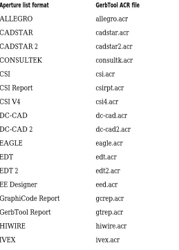
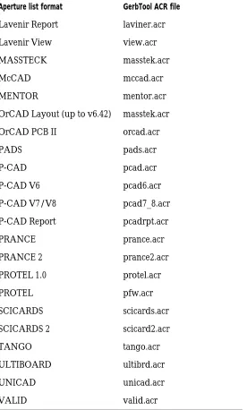
Converting a CAD aperture list
GerbTool provides aperture list conversion for most of the CAD and photoplotter aperture list formats in use today. The conversion process translates a CAD aperture list directly into GerbTool format, thereby reducing
[image:21.612.106.365.324.686.2]data-entry-related problems. Again, remember that you do not need to convert aperture files created by Layout. The following table shows the aperture list formats supported by GerbTool, along with the name of the Aperture Conversion Rule (ACR) file used for the conversion.
Table 1 Supported aperture list formats.
Aperture list format GerbTool ACR file
ALLEGRO allegro.acr
CADSTAR cadstar.acr
CADSTAR 2 cadstar2.acr
CONSULTEK consultk.acr
CSI csi.acr
CSI Report csirpt.acr
CSI V4 csi4.acr
DC-CAD dc-cad.acr
DC-CAD 2 dc-cad2.acr
EAGLE eagle.acr
EDT edt.acr
EDT 2 edt2.acr
EE Designer eed.acr
GraphiCode Report gcrep.acr
GerbTool Report gtrep.acr
HIWIRE hiwire.acr
Lavenir Report laviner.acr
Lavenir View view.acr
MASSTECK masstek.acr
McCAD mccad.acr
MENTOR mentor.acr
OrCAD Layout (up to v6.42) masstek.acr
OrCAD PCB II orcad.acr
PADS pads.acr
P-CAD pcad.acr
P-CAD V6 pcad6.acr
P-CAD V7/V8 pcad7_8.acr
P-CAD Report pcadrpt.acr
PRANCE prance.acr
PRANCE 2 prance2.acr
PROTEL 1.0 protel.acr
PROTEL pfw.acr
SCICARDS scicards.acr
SCICARDS 2 scicard2.acr
TANGO tango.acr
ULTIBOARD ultibrd.acr
UNICAD unicad.acr
[image:22.612.242.518.154.612.2]VALID valid.acr
Table 1 Supported aperture list formats. (continued)
Creating a new design
11 When creating a design, specify your aperture list When
creating a design, specify your aperture list normally. GerbTool converts it to the proper format automatically. Or you may select the Convert command from the Apertures menu and convert it prior to loading it into GerbTool.
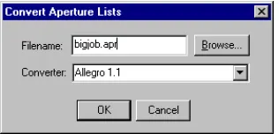
[image:23.612.101.259.279.355.2]To convert a supported aperture list to GerbTool format, select the Convert command from the Apertures menu, specify an input filename, then select the appropriate converter in the Convert Aperture Lists dialog box.
Figure 2 Convert Aperture Lists dialog box
Creating a new design
To create a new design, choose either Auto or Manual mode after you choose New from the File menu.
To create a design file automatically
1 From the File menu, choose New. GerbTool displays
the Create New Design Wizard dialog box.
2 Enter a name for the new design in the Design Name
text box, and specify a directory in which to create the design in the Design Folder text box, then choose the Next button. GerbTool displays the next dialog box in the Create New Design Wizard.
3 Choose Automatic, then choose the Next button.
GerbTool displays the next dialog box in the Create New Design Wizard.
4 Specify the path to the directory that contains the Aperture list files for the new design in the text box, then choose the Next button. GerbTool displays a dialog box informing you that the design has been created.
5 Choose the Finish button. GerbTool displays the Edit
dialog box and includes a list of all the layers found in the directory.
6 If you are using Gerber 274-D format, enter an
aperture list for each layer by selecting that layer from the list, then entering the aperture list file (*.APP) in the Aperture List field.
7 Choose the Edit button. GerbTool displays the Gerber
format dialog box.
8 Select the appropriate format, m.n setting, and zero
suppression, then choose the OK button. GerbTool returns you to the Edit dialog box.
9 Choose the OK button. GerbTool creates the new
design according to your specifications.
To create a design file manually
To create a design file manually in GerbTool, the layers and aperture lists must be in standard Gerber 274-D format.
1 From the File menu, choose New. GerbTool displays
the Create New Design Wizard dialog box.
2 Enter a name for the new design in the Design Name
text box, and specify a directory in which to create the design in the Design Folder text box, then choose the Finish button. GerbTool displays the Edit dialog box and includes a list of all the layers found in the directory.
Opening an existing design
13
4 Choose the Edit button. GerbTool displays the Gerber
format dialog box.
5 Select the appropriate format, m.n setting, and zero
suppression, then choose the OK button.
6 Choose the OK button. GerbTool creates the new
design according to your specifications.
Whether creating design files automatically or manually, GerbTool creates a design file named UNTITLED.GTD in the current directory. You can use the Save command on the File menu to save your design file under a different name.
Opening an existing design
Follow these steps to open an existing design.To open an existing design
1 From the File menu, choose the Open command.
GerbTool displays the Open Design dialog box.
2 Locate and select the design you want to open, then
choose the OK button. GerbTool displays the Edit dialog box.
3 If necessary, make any modifications, then choose the
OK button. GerbTool loads the appropriate files.
Saving a modified layer
If a layer has been modified or changed, you are given an opportunity to save it when you select the Save, Save As, or Save All command from the File menu.
Note
When GerbTool displays a list of files to save, you must select each
file you want to save. Only those files selected are saved.
Exiting GerbTool
GerbTool basics
4
GerbTool window
The GerbTool window consists of the following components:
n Main menu bar where you can “pull down” the
command menus.
n Toolbars where you can choose commands with a
single click.
n Settings control bar, where you control various
program settings, such as metric display mode and grid snap.
n Color toolbars where you can change layer colors and
visibility.
n Birdseye view that shows the current view window
relative to the extents of the loaded database.
n Adjustable pane dividers to split the drawing area into
multiple views.
n Drawing area where GerbTool displays all database
items.
n Crosshair cursor indicating the position of the mouse
within the drawing area.
Birdseye View
Layer Color/Visibility
Status Bar Film Box
Drawing Area Tool bars Menu bar Active Layer/Dcode bar
Coordinate display
Tool bars
Prompt area
Cross-hair cursor Tool bars
Pane Divider
GerbTool window
17
n Film box graphic that indicates the size of the current
film box.
n Status bar with prompt area where GerbTool displays
command messages.
n Tool tips on most window features including toolbar
buttons, control bar buttons and menu items.
Toolbars
Each icon within a toolbar represents a shortcut to a command. When you click on an icon in the toolbar, GerbTool executes the command associated with that icon.
Settings bar
Use the settings bar to quickly and easily control various options with a single mouse click. This section describes each button on the settings bar.
Sketch
This button toggles sketch mode on or off. When sketch mode is on, pads appear with an outline only, and traces appear as a single thin line. Besides speeding up redraw times, this mode can also help you spot stacked pads.
Overlay
View Composites
This button toggles the way GerbTool displays composite layers (extended Gerber and FIRExxxx only). When View Composites is on, the polarity of each layer, specified by the Polarity field within the Edit dialog box (from the Edit command on the Layers menu), is honored. If a layer is specified “Clear,” all data on that layer appears with the current background color.
DRC Errors
This button toggles the display of rule violation errors on or off. If DRC errors exist and this setting is on, GerbTool displays the DRC View Errors dialog box.
Note
For information on error reporting, see the DRC section in Chapter
7, Command reference.
Grid
This button toggles the system grid display on or off. Note
For information on grids, see the Grid section in Chapter 7,
Command reference.
Grid Snap
This button toggles grid snap mode on or off. When grid snap mode is on, the crosshair cursor automatically jumps to the nearest grid point.
GerbTool window
19
Orthogonal Snap
Use this button to toggle orthogonal snap mode on or off. When on, lines drawn interactively are forced to the specified angle.
Note
The current setting can be temporarily overridden by holding down
the
C
key.
Arcs 360°
This button toggles the method of creating arcs used by the Arc and Circle commands (on the Add menu). If on, all arcs are created using 360° circular interpolation. If off, all arcs are created using arcs of 90 or fewer degrees. This does not affect the way Gerber data is read from a disk file. It only pertains to adding new arcs with the Arc command (on the Add menu) and the Circle command (on the Edit menu).
Metric
This button toggles metric mode on or off. When metric mode is enabled, GerbTool shows all information and editing fields that represent sizes and distances (for example, coordinates) in metric format.
Active layer/D-Code
Coordinate display
You can dock the coordinate display control bar or allow it to “float” in a dialog box. It shows at a glance the current location of the crosshair cursor. The format of the display is controlled by the current setting of the Me button within the Settings bar or the Metric command on the Options menu and the file format of the active layer.
Color chooser bar
You can dock the color chooser bar or allow it to “float” in a dialog box. It is available at all times to change layer colors and visibility. When a layer is on, indicated by a red box around the layer number, it is both visible and editable. When a layer is off it is neither visible nor editable. When a layer is ref, indicated by a black box around the layer number, it is visible but not editable.
Birdseye view
You can dock the birdseye view or allow it to “float” in a dialog box. The black rectangle represents the database extents while the red rectangle represents the current viewing window. Use it to determine at a glance exactly where your current view window is located.
Split screen pane dividers
GerbTool window
21
Drawing area
The drawing area is the area between the menu bar and the status bar. All database items are displayed here.
Crosshair cursor
While the mouse position is within the drawing area, GerbTool displays the cursor as a crosshair. The exact location of the crosshair cursor appears in the Coordinate Display toolbar described above.
Film box
The film box represents the size of the film on which you will plot, and is a graphic display only. It does not become part of your Gerber database(s).
Tip
You can control the size and color of the film box using the Options
menu’s Configure command, described in Chapter 7, Command
reference.
Status bar
GerbTool displays command status and prompts in this area.
Tool tips
Design files
GerbTool uses design files. A design file, as created by GerbTool (or Layout), contains information about the Gerber files, and their associated aperture list files, that constitute a single PCB. This usually includes filenames for inner and outer signal layers, silkscreen layers, soldermask layers, and so on. GerbTool also associates an operating environment with each design file. Thus, when you load an existing design file, GerbTool restores the environment to the state it was in when you last saved the design file. This eliminates the need to continually reconfigure GerbTool each time you load a design.
Note
The default file extension for design files is configurable and is
easily changed using the Configure command on the Options menu.
Layout uses a .GTD extension for these files.
Aperture list files
Aperture list files define the characteristics of each Gerber D-Code used in a design. For each D-Code the aperture list file defines a shape, size, type, and NC drill tool number (see Chapter 7, Command reference). GerbTool stores aperture lists in ASCII format. This makes it easy to create and modify aperture lists. It also allows easy conversion from most CAD system aperture lists.
Note
The default file extension for aperture list files is configurable. You
can change it using the Configure command on the Options menu.
Layout uses an .APP extension for aperture list files it creates.
Using GerbTool commands
23
Using GerbTool commands
This section describes the different ways to use GerbTool commands.
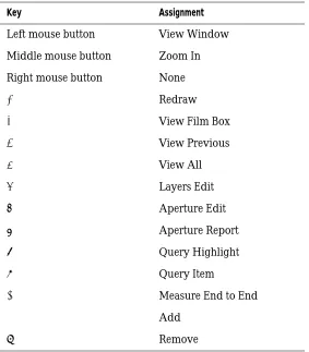
Mouse-button and function-key commands
GerbTool comes pre-configured with the following mouse button and function key assignments.
[image:35.612.99.382.310.633.2]The assigned mouse and function key commands are available any time GerbTool is idle (for example, there is no command prompt in the prompt area).
Table 2 Mouse-button and function-key commands.
Key Assignment
Left mouse button View Window
Middle mouse button Zoom In
Right mouse button None
1 Redraw
2 View Film Box
3 View Previous
4 View All
5 Layers Edit
6 Aperture Edit
7 Aperture Report
8 Query Highlight
9 Query Item
0 Measure End to End
! Add
Shortcut keys
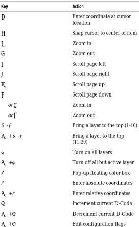
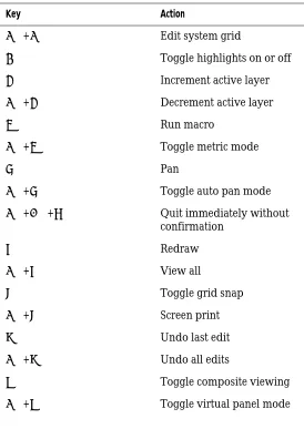
[image:36.612.238.510.234.676.2]Shortcut keys are available anytime GerbTool is idle, or when GerbTool prompts you to enter a point. Below is a list of the shortcut keys. GerbTool executes shortcut keys immediately without affecting the current command. Table 3 Shortcut keys.
Key Action
J Enter coordinate at cursor location
h Snap cursor to center of item
u Zoom in
d Zoom out
l Scroll page left
r Scroll page right
t Scroll page up
b Scroll page down +ori Zoom in
-oro Zoom out
0-9 Bring a layer to the top (1-10)
C+0-9 Bring a layer to the top (11-20)
a Turn on all layers
C+a Turn off all but active layer b Pop-up floating color box
c Enter absolute coordinates
C+c Enter relative coordinates d Increment current D-Code
Using GerbTool commands
25
Key Action
C+g Edit system grid
h Toggle highlights on or off
l Increment active layer
C+l Decrement active layer m Run macro
C+m Toggle metric mode
p Pan
C+p Toggle auto pan mode
C+A+q Quit immediately without confirmation
r Redraw
C+r View all
s Toggle grid snap
C+s Screen print u Undo last edit
C+u Undo all edits
v Toggle composite viewing
[image:37.612.100.374.149.536.2]Interrupting a drawing process
Anytime GerbTool redraws the display or highlights a window of data, you can halt the drawing process by
pressing the E key or clicking the right mouse button.
This does not affect the operation of the command and, in many cases, speeds up its operation.
Ending a command
You can end a command, or end at least one level of a
multistep command, by pressing the E key or right
Performance tips
5
Speeding up GerbTool operations
Using shortcut keys
Shortcut keys are a powerful feature of GerbTool. These keys are available any time GerbTool is waiting for you to enter a coordinate (point) or whenever it is idle (that is, when no command has been selected). Using these keys you can snap to the center of a database item, change which layers are viewed, undo edits, and so on.
Interrupting, redrawing, and highlighting
You can speed up any command that redraws the database or highlights a group of items by canceling thedrawing process. Click the right button or press the E
key to halt the redraw. This doesn’t affect the operation of the command; it affects only the redraw. Once you’re comfortable with the operation of GerbTool commands you will find that this ability significantly speeds things up.
Undoing edits
29
Undoing edits
The Undo command provides a high level of freedom when making database edits. You can experiment and try different edits without fear of data loss. Since undo is available as the shortcut key u, you can undo edits immediately without having to exit the current command. Undo works for all edits regardless of size, and there is no limit to the number of edits you can undo. Remember to enable the undo capability with the Configure command (Options menu) before making your edits, then use the Edit
menu’s Undo command or the shortcut key u to undo as
necessary.
Programming mouse buttons and
function keys
GerbTool’s easy-to-use graphical user interface is further enhanced with the versatility of programmable mouse buttons and function keys. Using the Configure command on the Options menu, you can program the mouse button
and function keys 1 through @ with commands that
Uses for GerbTool
6
Layer alignment
Layer alignment involves lining up all layers so that when you view multiple layers simultaneously, they are correctly aligned. Proper layer alignment is also crucial to the successful creation of a multilayer netlist.
First select a master layer with which all other layers should be aligned and select an item on that layer to use as a reference point. Choose the Align command from the Edit menu and select the item you chose as a reference point. Then, select an item on each layer to be aligned that corresponds to the reference point. As you select each item, GerbTool aligns the all other layers to the master layer.
Tip
You can use the shortcut zoom in, zoom out, and pan keys (see
Chapter 4, GerbTool basics
) to locate the reference and corresponding
items.
Creating NC drill files
Use the Drill command on the Tools menu to create an NC Drill file from any layer. Choose the format for the drill file by choosing the NC Format button within the Drill editing dialog box (shown in Chapter 7, Command reference). Usually, the layer you choose to create a drill file from represents the pad master for the entire design. When creating NC Drill files, GerbTool translates the Gerber flashes (except targets and thermals) into drill “hits.” The Tool field, in the corresponding aperture list for the selected layer, determines the tool call-out for each drill hit.
Note
Use the Report command from the Apertures menu to determine if
you have a tool assigned to each flash. Edit the aperture list, if
required, so all flashes are assigned a tool.
Importing drill files
33 Perform panelization prior to executing the Tools menu’s
Drill command. If your drilling equipment has a small memory capacity, perform a “virtual” panelization. This allows GerbTool to insert the needed step and repeat codes into the output drill file. Preferably, if your drilling equipment has enough memory, you should perform a normal non-virtual panelization. This results in a fully optimized panel for the maximum drilling efficiency.
Importing drill files
Use the Drill command from the Import menu to load an NC Drill file into the active layer. Layout creates a drill file, THRUHOLE.TAP, that you can import in order to automatically include the drill information for your design.
You can also create a new empty layer first by selecting the Create command from the Layers menu. Make sure that the layer you choose is the active layer.
When loading an NC drill file, GerbTool converts the drill hits into Gerber flashes. Each tool called out in the drill file is located in the aperture list for the active layer. If GerbTool can’t find a tool, it adds an aperture to the list with an “Unknown” shape and the correct tool
assignment. You can then edit the aperture to correct the shape, size, and so on.
Panelizing
With GerbTool, panelizing is a simple, one-step process when using the Auto Panel feature. After activating the layers to be panelized (only), select the Panelize command from the Tools menu, ensure that the Auto Panel button is selected (shown in Chapter 7, Command reference), and enter the minimum image border-to-border spacing in the X and Y fields. The spacing you specify should be between adjoining edges of the intended images. GerbTool
automatically calculates the maximum number of images that will fit inside the current film box. After asking for confirmation, GerbTool completes the panelization process. Depending on the setting of the Virtual button, GerbTool either copies the proper number of images into the database or notes the number of copies and their location for display purposes.
Note
You can use the right mouse button or press the
E
key to stop
the drawing process anytime during the panelizing process. This
usually provides a noticeable improvement in the overall time to
complete the panelizing process without affecting the finished
panel in any way.
Viewing or printing Gerber
274-D composite layers
You can use black and white for layer colors, to provide accurate viewing of composite power and ground layers. Setting the negative layer to white on a black background and the positive layers to black results in a realistic depiction of the final film.
Merging designs
35 To print a composite layer, view your composite layers as
described above, then use the Print command (from the File menu). The printed image appears on the page exactly as it does in the display.
Note
Since the image for printing is created in a high resolution
off-screen bitmap, the film box and display grid may appear on the
output page. You can disable this by setting the film box color to
the background color using the Film box command (Options menu)
and disabling the display of the grid using the Grid command
(Options menu), or shortcut key
G.
Merging designs
You can merge two or more designs into a single Gerber file so they can be photoplotted simultaneously. This reduces manufacturing costs by making full use of photoplot film.
In order to merge designs in this manner, the following conditions must exist:
n Each file must be in the same Gerber format and have
the same m.n values, and zero suppression.
n Each file must use the same aperture list. That is, the
size and shape of each D-Code must be the same in each aperture list.
n The respective layers in each design must be the same.
For example, layer 1 of each design must be the silkscreen, layer 2 of each design must be the top layer, and so on.
To merge design files
1 From the File menu choose the Open command and
select the .GTD file for the first design. GerbTool displays a list of layers in the Layers-Edit dialog box.
2 Choose the OK button. GerbTool displays the design
at coordinates 0:0 in the lower left of the Film Box
.
3 From the Edit menu, choose the Scale command. The Scale and/or Offset Layers dialog box appears. Choose the desired offset value.
4 Select All Visible from the Layers drop down list.
5 Choose the OK button. GerbTool responds with an
error message: “Command cannot be undone. Continue?”
6 Choose Yes. This shifts the first design.
7 From the File menu, choose Merge and then choose
Design. In the Merge Design dialog box, choose the second design. The second file appears in the film box.
Note
OrCAD recommends that you merge only Gerber 274-D files.
Drawn pads
Occasionally, CAD systems may output an irregularly shaped or sized pad using multiple draws to “fill in” the shape, rather than a more efficient single flash. This results in larger Gerber files than necessary and increases processing times. Also, it is virtually impossible for high-level CAM tools such as DRC to recognize the drawn
pads as true pads, rather than as collections of traces. The difference between a typical drawn pad and a comparable
flash is shown below.
Figure 3 Drawn pad versus a flash.
Automatic silkscreen clean-up
37 The drawn pad in this example requires 27 separate
Gerber commands to accomplish what one Gerber flash can accomplish. Thus, if you have 2000 of these drawn flashes, you’ll have a Gerber file with at least 54,000 lines when flashes could accomplish the same thing in only 2000 flashes.
Using the Pads command from the Convert menu, you can convert all your drawn pads to flashes. You do this by identifying one occurrence of a drawn pad and allowing GerbTool to find all drawn pads that match. And, to increase GerbTool’s ability to recognize matching drawn pads, you can specify a tolerance value to compensate for some CAD systems’ round-off errors. By specifying a tolerance, you allow GerbTool to relax its criteria for determining matching drawn pads.
Tip
Converting drawn pads to flashes should be the first thing you do
to your designs. This usually ensures trouble-free conversion. Also,
you must convert all drawn pads to flashes before generating a
netlist or running most other CAM tools.
Automatic silkscreen clean-up
GerbTool has the ability to automatically clean up a silkscreen where lines touch or are too close to the pads. Using the Fix Silkscreen command from the Tools menu, you specify the layer(s) that the silkscreen and pad master are on and the minimum spacing that must be maintained between the silkscreen data and the pads. If you want, you can use window mode to clean up isolated areas rather than the entire silkscreen layer. GerbTool then cleans up all areas where silkscreen lines are too close to a pad. Each offending line is moved just enough to eliminate the violation.Creating a soldermask layer
Creating a soldermask is a simple and easy process using the Scale command, from the D-Code selection on the Edit menu.
First, create the soldermask layer by copying the pad master layer onto a new layer. Use the Copy command to copy the pad master to the new layer. When copying, select Create Layer from the Copy to Layer fields drop-down list. This creates a new layer for the new soldermask data.
Transcoding
39
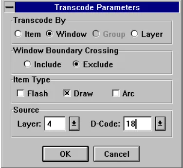
Transcoding
Using the Transcode command (from the D-Code
[image:51.612.100.288.282.455.2]selection on the Edit menu), you can transcode (transform D-Code) item by item or by selecting a group. Using selection criteria, you can choose exactly which D-Codes are transcoded. For example, to transcode only draws with a D-Code of D18 on layer 4 and within a particular window, specify the selection criteria as shown in the following example:
Figure 4 Restrictive selection criteria.
Snoman pad and trace filleting
Snoman is a highly configurable dialog box that specifies a method of optimizing pad/trace junction points. This is often referred to as filleting or teardropping (see Appendix C, Snoman concepts for a technical description of Snoman). The purpose of Snoman is to increase your manufacturing yield by adding more copper in the area of the pad/trace junction, thereby eliminating any possible pad/trace separation. Snoman is used primarily when dealing with small pads and traces (such as micro vias in the 30 mils or less range) but can be used anywhere to preventpad/trace separation. Snoman provides additional versatility by allowing you control of the size and location of the generated Snoman pads, along with an integral DRC to eliminate any possible spacing violations.
Note
Trivia: Snoman derives its unusual name from the appearance of a
Snoman pad placed on top of a host pad, which resembles a “real”
snowman.
Command reference
7
File menu
The File menu selection displays commands for dealing primarily with files and directories. The menu commands are described in the following sections.
New
The New command presents the New Design Wizard as shown below.
Figure 5 New Design Wizard.
Design Name
Enter a filename for the new design file.
Design Folder
File menu
43 Clicking on the Next button moves you to the next step
and presents you with a choice of two modes: Automatic and Manual.
Automatic
When you select Auto mode, GerbTool builds a design file for you automatically. You specify the source folder and GerbTool determines which files are Gerber or aperture lists. The Gerber filenames are sorted first alphabetically, and then by layer number, if one is found. If an aperture list is found that is not already in GerbTool format, GerbTool tries each configured aperture list converter until a match is found. Finally, each aperture list is matched to a suitable Gerber filename. GerbTool then displays the Edit dialog box where you can make any final adjustments, if necessary.
Note
This command is affected by the number of aperture converters
configured and by the filename extensions that are ignored. In
general, fewer aperture list converters and more ignored filename
extensions result in faster performance.
Manual
When you select Manual mode, GerbTool creates an empty design file for you, and then displays the Edit dialog box for you to enter the Gerber files and aperture lists.
Open
This command displays the file chooser and prompts you for a design file to load. You can use a wildcard
Close
This command closes the current design.
Save
Select this command to save the current design file, and optionally, any modified layers or aperture lists. This command does not close the current design; you can continue to work on it after saving. You must use this command, Save As, or Save All to save modified layer data.
Save As
Select this command to save the current design file under a different filename and optionally any modified layers or aperture lists. This command does not close the current design; you may continue to work on it after saving.
Save All
File menu
45
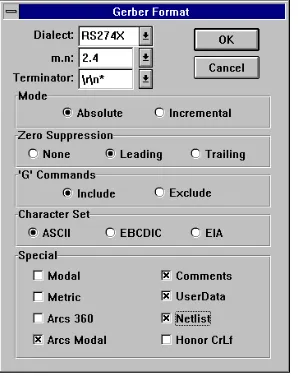
Format
This menu selection has two commands: Gerber and Drill. When you select one of these commands, GerbTool displays a format dialog box in which you set the global formats for the file type in question.
[image:57.612.104.253.301.490.2]Note
GerbTool supports both global and local formats. Global formats
apply to all layers that do not have a local format assigned to them.
Use this command to edit the global formats only. See the Edit
command in the Layers menu for more information on local
formats.
Figure 6 Typical format dialog box.
You can specify the correct format for that type of file (in this example, Gerber) by changing the settings in a format dialog box. The illustration above shows a Gerber Format editing dialog box, which includes the following fields:
Dialect
m.n
Coordinate format such as 2.3. This specifies 2 decimal digits before an implied decimal point, and 3 following (for example, 12250 represents 12.250 if the coordinate format is 2.3). Because of limitations in the representation of arcs in Gerber format, it is best to use at least a 3.4 coordinate precision for designs that include arcs.
Terminator
Indicates the block terminator (EOB). Use \r to indicate a carriage return (ASCII 13) and \n to indicate a line feed (ASCII 10).
Mode
Choose Absolute or Incremental (see Glossary for descriptions of these terms).
Zero suppression
Indicates whether leading zeros or trailing zeros are suppressed, or there is no zero suppression.
“G” commands
Indicates whether GerbTool includes “G” commands (for example, G01) when you output Gerber files.
Special
You can enable Modal compression to reduce the size of your files by removing all redundant draft codes and coordinates. Or, you can enable Metric mode indicating that your files are in metric format. You can also specify whether all circular interpolated arcs should be
File menu
47 You can toggle between metric and inch format, as well as
change m.n formats after loading a design. If you change formats after loading, all layers are marked as modified.
Note
If you change formats after loading and do not save all layers, the
next time you load that design, the saved format may not match
that of the unsaved Gerber files.
Selecting the Netlist button tells GerbTool to save netlist information within the Gerber file. If you have previously saved a Gerber file with netlist information, you can remove it by deselecting the Netlist button and saving.
Note
It is important that you specify the correct format before loading a
new design. The critical format items are m.n, mode, and trailing
zeros. If you load a design with an incorrect format, GerbTool will
display it with unpredictable results. If you inadvertently load a
design this way, reload the design and click on the Format button
of the Edit dialog box to correct the format.
Merge
The Merge command has two modes: Design and Gerber.
Design
Selecting this command allows another complete design to be merged layer by layer into the current design. If a layer from the external design doesn’t exist in the current design, you will be prompted to create a new layer.
Gerber
Use this command to merge a Gerber file into the currently active layer. GerbTool prompts you for a filename. You can use a wildcard specification to obtain a list of files from which to choose. The specified filename is not added to the list of loaded layers. Rather, the contents of the file are read in and appended to the active layer.
Import
The Import command has a number of options: BARCO DPF, HPGL, IPC-D-356, Drill and DXF.
BARCO DPF
Use this command to import one or more BARCO files into the currently loaded design. This command begins importing the specified files into the active layer if it is empty. If it is not empty, GerbTool creates a new layer following the active layer. GerbTool creates as many layers as necessary to import all the files you specify.
HPGL
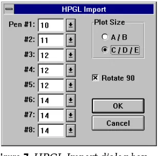
[image:60.612.238.394.393.545.2]Use this command to merge an HPGL plot file into the currently active layer. After selecting a file to import, GerbTool displays the following HPGL import dialog box.
Figure 7 HPGL Import dialog box.
Using this dialog box, you can specify the expected plot size, whether to rotate the plot data and which D-Codes to use for each HPGL pen.
File menu
49
IPC-D-356
Use this command to import an IPC-D-356 netlist into your design. Because an IPC-D-356 netlist contains information pertaining to pads and not traces, GerbTool must generate an internal netlist prior to importing an IPC-D-356 netlist, to ensure that your database contains a full and complete netlist after importing. While this may sound redundant, the added benefit of an “automatic netlist comparison” is well worth it. The netlist
comparison feature produces a report file detailing any differences between the internal and the imported netlists, in addition to highlighting any differences. Optionally, you can update the database UserData fields with the component/net data from the IPC-D-356 file. Then, you can use GerbTool commands, including the Item Info command (on the Query menu), to examine and
manipulate the true reference designators, pin numbers, and so on.
GerbTool creates a pad for each test point in the input file. These pads are based on the size and location of the test points and are placed on the active layer. It is a good idea to create an empty layer and make it the active layer before importing an IPC-D-356 file.
GerbTool converts the IPC information into Userdata attached to the pads and traces in the Gerber file. For pads, the format is “netname:component(pin).” For traces, only the netname is attached.
The list below shows possible error messages that can come from importing an IPC-D-356 file:
No IPC data for location 2.8750, 3.7500 Layer:1
There is a pad on this layer that does not have any matching IPC information.
No Gerber data for location 1.5980, 4.3800 ID 45:
() idx 43
Gerber Net Re-assignment: GerbTool net 78 Locations: 1.7980,0.8300 and 2.7980,4.2800 IPC nets 55:() 171:()
The IPC file has tried to associate the 2 nets, “55:()” and “171:()”, to the GerbTool net number 78.
IPC Net Re-assignment: GerbTool nets 123 250
Locations: 2.0980,1.0300 and 3.7980,4.3800 IPC net 78:()
The IPC file has tried to give the same net information “78:()” to the GerbTool nets 123 and 250.
Drill
Use this command to import an NC Drill file onto the active layer.
Note
This command requires that you ensure the critical format items
(mode, m.n and trailing zero suppression) for the file, or files,
being loaded match those of the currently specified drill format.
DXF
Use this command to import a DXF file into your design. You can map each layer contained within the DXF file to one or more GerbTool layers. This flexibility allows you to duplicate information onto multiple layers. For instance, a pad master layer might need to be merged onto each layer containing traces.
Likewise, you can map more than one DXF layer to a single GerbTool layer.
File menu
51 You can also map blocks to apertures manually, or
automatically when you export from GerbTool, if you turn on the Auto Map feature. GerbTool automatically explodes blocks that you don’t map to apertures into their individual draw components.
Note
Mapping blocks to equivalent apertures makes design editing
easier and decreases the size of the database.
GerbTool supports standard SHX font files and SHX Unifont files, both for text and shape entities. If text within
the DXF file refers to a font that is not present on your system, or the font file is of an unrecognized type, GerbTool uses a standard font in its place.
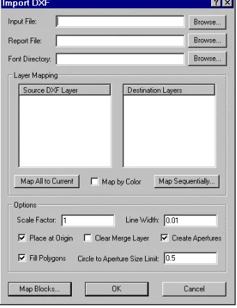
[image:63.612.102.272.354.575.2]GerbTool displays the following dialog box.
Figure 8 Import DXF dialog box.
Input File
Report File
Specifies the report file to generate.
Font Directory
Specifies the directory for SHX font and shape files.
Source DXF Layer
Specifies the current DXF layer you selected for mapping to zero or more destination layers in GerbTool.
Destination Layer
Specifies the layers that you selected to receive the contents of the Source DXF Layer. Note that more than
one destination layer can be selected by keeping the C
key pressed during selection.
Map All to Current
Merges all DXF layers into the current GerbTool layer.
Map by Color
Select this to map DXF file items onto GerbTool layers based on color. Items of color 1 (red) appear on GerbTool layer 1, color 2 (yellow) on GerbTool layer 2, and so on.
Though many drawings use colors 1 through 9 only, the valid range is 1 through 255.
Map Sequentially
Displays a dialog box you use to sequentially map DXF layers to GerbTool layers. You can specify the first GerbTool layer to receive DXF layer information, and you can exclude DXF layer 0 from the mapping.
File menu
53
Scale Factor
Specifies the scale factor GerbTool uses when merging. The default scale factor is 1. A design drawn using metric units may require that the scale factor be changed
appropriately (e.g., if the units are millimeters, use a scale factor of .0394).
Line Width
Specifies the line width, in inches, GerbTool should use for zero-width lines. The default width is 0.01 inches.
Place at Origin
Specifies that GerbTool places the DXF design with its lower-left corner at the GerbTool origin.
Clear Merge Layers
Specifies that GerbTool empties all merge layers prior to importing DXF information.
Create Apertures
Specifies that GerbTool creates an aperture for drawing lines when an equivalent aperture does not exist. If not checked, GerbTool uses the next smaller aperture. If a next smaller aperture does not exist, it uses the smallest.
Map Blocks
Displays a dialog box that you use to map blocks in the DXF file to apertures in GerbTool. If Auto Map is selected then all blocks to be mapped must have their names constructed in the same manner as GerbTool DXF Export constructs block names. If Clear Map is selected, then all block mapping associations are removed.
Export
Using the Export command you can export your Gerber data into BARCO DPF, IPC-D-350, IPC-D-356, DXF, HPGL and PostScript data formats.
BARCO DPF
GerbTool exports designs in the BARCO DPF format to a separate file for each layer. You select which layers to export and what the output filenames will be. If you enable the Auto Rename button GerbTool outputs all selected layers, renaming each layer automatically using the filename extension specified in the New Extension field.
IPC-D-350
GerbTool exports designs in the IPC-D-350 format to one disk file, containing all layer data specified within the currently loaded design. The specified output file contains all data necessary to reproduce your design on any IPC-D-350 compatible device.
IPC-D-356
GerbTool exports designs in the IPC-D-356 format to one disk file containing all layer data specified within the currently loaded design. The specified output file contains all netlist data associated with the current design.
DXF
File menu
55 The Blocks section contains blocks with information
necessary for displaying each of the apertures used in the design. You are not required to acquire an equivalent set of blocks for reproducing the apertures that can appear within GerbTool.
Note
DXF does not support the concept of polarity. Negative polarity
areas within custom apertures will not appear correctly when the
file is imported into other applications.
Block names are created with a convention that allows for easy import back into GerbTool when the DXF Import Auto Map feature is used. Each pad in the design is output into the DXF file as a block insert. By processing the pads as references in this manner, instead of duplicating the draws for each instance, can significantly reduce the size of the generated file.
[image:67.612.101.283.387.455.2]When exporting to the DXF format, you see the following dialog box.
Figure 9 Export DXF dialog box.
Output File Specifies name of the DXF file to create when exporting.
HPGL
[image:68.612.236.424.268.447.2]GerbTool provides three modes of output when plotting on an HPGL compatible plotter: Sketch, Outline and Fill. Sketch mode is the fastest but does not show width on draws and some flashes such as Donuts. Outline mode shows true width on all objects but they are outlined only. Fill mode shows true width, and all objects are completely filled in as they would appear on a photoplot. Fill mode is the slowest and is extremely hard on plotter pens.
Figure 10Export HPGL dialog box.
You can also specify output file, media size, plot offset, pen width, pen speed, pen number for flashes and draws, pen number for the optional border, scale, whether to rotate 90° and whether to plot only pads (flashes). The offset values are applied independent of the scale
specified. Plot offsets allow you to plot multiple images on one sheet.
File menu
57 Batch Mode This option instructs GerbTool to output
each visible layer to a separate output file. During batch mode operation, if the Output File field is empty, the output filenames are derived from the filename associated with each layer and the currently configured HPGL filename extension (see Options/Configure later in this chapter). If, on the other hand, the output file field contains a filename, GerbTool appends a number
representing the number of the input layer (i.e., demo.001, demo.002, and so on).
Interactive Mode Enabling Interactive mode allows you to interactively position each layer on the output page. To position an image on the page, simply click your mouse over an image to select it and then drag the image to the desired location and release the mouse button (or click again).
During interactive plot positioning, a menu of buttons is provided along with several plot specific nested
commands.
Figure 11HPGL interactive control form.
The Plot button saves the page layout and plots the data. The OK button saves the page layout and quits the interactive session without plotting. The Reset button resets the images to their initial positions for this session (if the form has been pinned) or simply quits the
interactive session without saving the page layout or plotting the data.
Note
There are two files within the GerbTool program directory that
affect each HPGL plot. The files HPGL.INI and HPGL.DEI are
prefixed and appended, respectively, to the actual plot output. If
you have any special requirements, you may edit these files as
needed.
PostScript
GerbTool provides PostScript output allowing you to plot your data on any device that supports PostScript,
including typesetters capable of producing production quality artwork.
There are two modes of output when outputting PostScript: Outline and Fill. Outline mode shows true width on all objects but they are outlined only. This allows you to check for overlapping features. Fill mode shows true width, and all objects are completely filled in as they would appear on a photoplot. Fill mode may produce a larger output file.
Figure 12Export PostScript dialog box.
File menu
59 Gray Scale Enabling Gray Scale mode allows you to
output accurate black and white composites, as well as halftone images. When Gray Scale mode is disabled, all colors other than the background color are printed as black. When enabled, all colors (other than black/white) are converted to a different gray scale.
Add Border This option adds a border to your plots. To control what text GerbTool adds to this border, see the Configure section under the Options menu later in this chapter for a description of the Print Border Text configuration parameter.
Batch Mode This option instructs GerbTool to output each visible layer to a separate output file. During batch mode operation, if the Output File field is empty, the output filenames are derived from the filename associated with each layer and the currently configured HPGL filename extension (see the Configure section under the Options menu later in this chapter). If, on the other hand, the output file field contains a filename, GerbTool
appends a number representing the number of the input layer (i.e., demo.001, demo.002, and so on).
Page Setup
Use this command to configure how GerbTool will format each page printed by the Print command.
Scale
Specifies the scale for the print output. A scale of “1” indicates a 1:1 correspondence between the print output and the design. A scale of “2” indicates a 2:1
correspondence between the print output and the design, and so on.
Overlap
Indicates the amount of overlap for pages of a multi-page plot, to allow for proper alignment when taping the pages together.
Add Border
This option adds a border to your print output.
Batch Mode
This option instructs GerbTool to output each visible layer to a separate output file. During batch mode operation, if the Output File field is empty, GerbTool derives the output filenames from the filename associated with each layer and the currently configured Postscript filename extension (as explained in the Configure command discussion, later in this chapter). If, on the other hand, the output file field contains a filename, GerbTool appends a number representing the number of the input layer (demo.001, demo.002, and so on).
Color/Grey Scale
File menu
61
Fit to page
Specifies that the plot is automatically fitted to the page size.
Overlay
Specifies that GerbTool prints a third color in areas where two differently colored objects are superimposed over each other. This option applies only if you have a color-capable printer.
Print Background
Specifies that GerbTool prints the color for the design background. By default, this option is off.
Sketch
Specifies that GerbTool draws only the outlines for objects in the design, rather than filling in those objects.
Window
Specifies that GerbTool prints only that area of the design that falls within a user-defined window.
Select this command when you want to print the viewed layers. Use this command to print your design on any printer/plotter supported by Windows.
Print Preview
Use this command to view how each page of your design would print before actual printing begins.
Printer Setup
Use the Printer Setup command to select and configure the current Windows default printer.
Exit
Select this command when you want to exit GerbTool. The current design file can be saved, and you will be
Edit menu
63
Edit menu
The Edit menu includes these commands: Undo, Select, Item, Copy, Move, Delete, Clip, Join, Rotate, Mirror, Scale, D-Code, Align Layers, Origin, and Purge.
You can modify the selection criteria for all editing commands that require you to modify one or more database items. GerbTool commands are flexible in the selection of data to modify. For example, you can select single items, or items within a window, group, or complete layer.
Figure 14Typical selection criteria.
With this dialog box, you can control whether flashes, draws, arcs or any combination of all three are selected. Further, you can select whether a single item, window, group or layer is selected. In Window mode, you can select whether to include items that cross the window boundary. And finally, you can select whether to restrict the selection to a particular layer or D-Code.
You can end any editing command by choosing the right
button, pressing the E key, or selecting another menu
item.
Undo
Use this command to undo changes you’ve made to the currently loaded database. Undo information is saved in a last in - first out fashion. This means that you undo changes in the reverse order in which the changes were made. This allows you to undo the most recent changes first. You may also use the shortcut key U to invoke the undo command even during another editing command.
Note
Undo must be enabled with the Configure command (Options
menu) prior to making any edits, if you plan to use this command.
Undo