Design, Analysis and Fabrication of an Effective
Steering System
Khan Noor Mohammad1, Vatsal Singh2, Nihar Ranjan Das3, Pritam Akangire4, Harshdeep Singh Rajpal5, B.R.Patil6
1, 2, 3, 4, 5, 6
Mechanical Engineering Department, MIT Academy of Engineering
Abstract: The main objective of steering system is to manoeuvre the vehicle while maintaining pure rolling condition and giving maximum directional stability under toughest of the terrains. This article deals with the designing and manufacturing of an efficient and light weight steering system for an All-Terrain Vehicle (ATV) using rack and pinion mechanism. The main focus was given on driver comfortability, achieving maximum Ackermann percentage and steering camber control for which brainstorming and selection of proper joints along with the selection of proper material for the components was done. Various front geometries have been iterated upon and the one which met our primary targets was finalized. This study summarizes in brief the design parameters, targets and considerations followed by fabrication and assembly of the system
Keywords: Ackermann geometry, Steering Effort, Steering Arm, Kingpin inclination,
I. INTRODUCTION
The basic function of steering system is to convert the rotational input from the driver into angular deviation of tires to give directional characteristics to the vehicle. The rack and pinion mechanism was selected for steering due its simplicity and effectiveness. In rack and pinion mechanism, the wheels are steered by the linear motion of the rack caused by the rotation of pinion. The very first step towards designing the steering system was selection of a proper compatible steering geometry. Ackermann steering geometry seemed to be the appropriate one, as it provides camber and toe adjustments along with it being compatible with suspension system as well as satisfying the law of correct steering. The primary target was to improve the design which leads to better outputs and efforts were made in that direction along with overall weight and cost reduction of the entire steering system.
A. Design Objectives
The main objective while designing the steering system was to get an optimized and stable front geometry with minimum turning radius, low steering effort and good amount of Ackermann percentage along with optimum steering camber change
B. Design Targets
To satisfy the system requirements various designing targets were set which are as follows.
1) To reduce the steering effort.
2) To reduce the turning radius of buggy.
3) To avoid any kind of play in the system.
4) To reduce weight of the components used in the system.
C. Design Considerations
To achieve above targets, following considerations were made to make the system more stable and efficient.
II. DESIGNPROCEDURE
Design procedure gives step by step description of the proceedings done while designing the steering system so as to meet the objectives and the targets.
A. By discussing with other departments, the track width and wheel base were decided.
B. By considering above parameters we started designing proper compatible steering geometry on LOTUS software.
C. In order to achieve steering targets, iterations were carried out by virtual simulation on trial and error basis method to decide
the dimensions of parts and the components used.
E. The iterations were made on positions of components like Rack position, Steering arm length, Rack travel and Rack length to achieve optimum Ackermann percentage and turning radius with low steering camber, mechanical trail and scrub radius.
III.ITERATIONS
Iterations were made after finalizing the Steering Ratio by assuming the Values of Track Width, and Wheelbase, Rack Length, Rack Position (w.r.t Stub Axle), Rack Travel and Steering Arm Length. These above parameters were varied in order to study their effects on other parameters like Turning Radius, Inner Tire Angle, Outer Tire Angle and Ackermann Percentage and at last the best outcome was selected as the final iteration. The iterations were done on both software as well as on sketch, for cross checking the design and to implement it in practical conditions
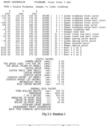
[image:2.612.138.483.230.635.2]A. Iteration 1 1) Coordinates
Fig 3.1: Iteration 1
2) Observations
Parameters Results
Turning radius(mm) 2719
Inner tire angle 35.92°
Outer tire angle 26.21°
Percentage Ackermann 64.46%
B. Iteration 2 1) Coordinates
Fig 3.2: Iteration 2
2) Observations
Parameters Results
Turning radius(mm) 2318
Inner tire angle 38.20°
Outer tire angle 27.43°
Percentage Ackermann 75.32 %
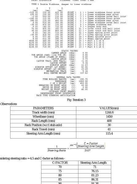
C. Iteration 3
Fig Iteration 3
1) Observations
PARAMETERS VALUES(mm)
Track width (mm) 1244.6
Wheelbase (mm) 1450
Rack Length (mm) 400
Rack Position (w.r.t stub axle) 30
Rack Travel (mm) 41
Steering Arm Length (mm) 115.4
Considering steering ratio = 4.5 and C-factor as follows:-
C-FACTOR Steering Arm Length
70 71
75 76.15
80 81.23
85 86.31
90 91.38
95 96.46
For example
= 71
IV. DESIGNSPECIFICATIONS
The selected design with all the calculations is given below
A. Ackermann Law
It states that, whenever a vehicle takes a turn, the projections of the stub axle of front wheels will meet at a point on the proj8ection of rear axle, called instantaneous centre.
For stabilizing the vehicle, the system should also follow correct steering angle. This states that for taking a proper turn with all the tires rolling on the ground having maximum contact patch, the angle turned by the inner tire should be greater than the angle turned by the outer tire. It gives a relation between inner tire angle, outer tire angle, wheelbase, and track width, which are the basic parameters to decide the stability and position of the instantaneous centre, followed by turning radius.
The mathematical expression for Ackermann is as follows;
The values of track width and wheelbase that were finalized from the iterations are given below; Track width = 1244.6 mm
Wheelbase = 1450 mm
The value of inner tire angle turned is found by the geometry and the value of outer tire angle is found by the Ackermann’s Mathematical expression. This is done to verify the outer tire angle turned by Mathematical expression with outer tire angle turned geometry.
From Geometry Inner tire angle turned = Ø = 48.200
cot (48.2) - cot (Ɵ) =
Therefore, Outer tire angle = Ɵ = 29.740
is approximately same as that of the value which we got from the geometry simulation on Lotus).
B. Turning Radius
The Turning Radius determines the minimum value of radius in which a vehicle can take a turn. To have good manoeuvrability smaller turn radius is required with stability and without violating Ackerman law. Following formula is used to calculate the Turning Radius;
Turning Radius (inner)
Turning Radius (Outer)
Where
Pivot distance = 1155.6 mm
And thus, the Inner and Outer Turning Radius are Calculated which are shown below; Inner tire Turning Radius = 1910mm
Outer tire Turning Radius = 2878.50mm
C. Ackermann Percentage
calculating Ackermann Percentage, the Ackermann Value is needed to be calculated first. Formula for calculating Ackermann Value is shown below:-
Ackermann value =
By Calculating;
Ackermann value = 48.260
Now we are able to calculate the Theoretical Ackermann Percentage by following formula;
Ackermann Percentage =
Hence, Ackermann Percentage = 99.89%.
D. C-Factor
C-Factor is the linear distance travelled by rack in one rotation of the pinion. To make steering system more responsive. The value of C-Factor should be as large as possible But, it should be kept in optimum range to keep the Pinion diameter in limit.
C-factor =
By Calculating, we get C-Factor = 101 mm
The Steering Ratio is the ratio of Angle of Steering Wheel Rotation to Angle Deviated by the Tire. It’s the measure of responsiveness of steering system. For a steering system with rack and pinion as the steering gears, steering ratio calculated by the formula as follows;
Therefore, values of C-factor and Steering Arm Length are as follow; C-factor= 101 mm
Steering Arm Length = 111.71 mm We get Steering Ratio as;
Steering ratio = 5.6:1
This value of steering ratio shows that the system designed is responsive and will ease the driver to control the vehicle.
E. Steering Effort
It is the amount of force applied at the steering wheel to steer a vehicle. If the force is less, it is more comfortable for driver to control a vehicle. Various parameters influencing the value of steering effort are mechanical trail, scrub radius, lateral force and traction force.
Following parameters, we took from Steering Geometry Mechanical trail = 5.33 mm
Scrub radius = 22.37 mm
For calculating the steering effort, we determined the steering characteristic of the vehicle by calculating the understeer gradient.
δ =
Therefore, k = 3.55.
The negative under steer gradient gives the oversteer characteristic of the vehicle. Now Calculating the Moment on Tire;
Lateral force on front tires = 4000 N Moments on Tire:
Lateral Force × Trail = 4000 × 5.33 = 21320 N-mm Traction Force ×Scrub =555.23 × 22.37= 12420 N-mm` Total Torque = 21320 + 12420 = 33740 N-mm
Force = 449.87N
Tie rod inclination (α) = 29.64 Force on rack = Force × cos 29.64 Force on rack = 390.96 N
Pinion radius = 16.95mm = 0.0169m
Torque on Pinion = Force on Rack × Pinion Radius Torque on pinion = 6.626N-m
As we know that,
Torque on steering wheel = Torque on pinion Therefore,
Torque on steering wheel = 6.62 N-m Steering wheel radius = 150 mm = 0.15 m
Steering Effort = 44.17 N-m.
F. Rack and Pinion Gear Design
The main consideration while designing the gears of rack and pinion is to avoid the interference between Rack and Pinion and to minimize the backlash. So as to avoid any play in the system.
As we know that for no interference the module should be m ≤ R x sin2Ø.
Where;
Ø = pressure angle
C-Factor = 101 mm = 2π×R
R = 16 mm and PCD = 32 mm
m ≤ 16×sin 2 20 0
m ≤ 1.85
The module shouldbe less than or equal to 1.85.
Some standard module available are as follows:
1st choice 1.00 1.5 2
2nd choice 1.25 1.75 2.25
Therefore,
Module (m) = 1.5 mm
Standard Addendum = m = 1.5 mm
Standard Dedendum = 1.25 x m = 1.875 mm Now we know that,
PCD = m x No. of Teeth on Pinion No. of Teeth on Pinion = 21
To Calculate No. of Teeth on Rack using following formula;
No. of Teeth on Rack =
Centre distance = PCR of pinion + Rack Shaft Radii - Module CD= 16 +16 -1.5 = 31.5 mm
After designing of rack and pinion they were analysed using ANSYS software which assured us that the teeth of Rack and Pinion will not fail with the factor of safety coming out to be 2.5.
Specifications of the Selected Geometry.
Parameters Results
Turning radius 1910 mm
Inner tire angle (Ø) 48.20
Outer tire angle (Ɵ) 29.740
Percentage Ackerman
99.89%
Rack travel 82 mm
Steering arm length 111.72 mm
Tie rod length 332 mm
V. THEORETICALDATAANALYSIS
A. Spline Calculations
Formula for torque transmission is as follows;
Mt = Pm ×A × Rm
Where;
Pm = 6.5 N/mm2
A = = 630 mm2
= 8.75 mm
So, Maximum Torque we can transmit is
Mt = 35.831 N-m
And Torque Transmitted by Driver is 7000 N-mm which is safe.
Now Calculating Shear Stress on Splines as follows;
Considering FOS as 2.5 and Yield Strength as 276 MPa
Ƭpermissible = (0.5 × Syt) ÷ 2.5 = 55.2 N/mm2
Force is 777.78 N and Area is 17.5 mm2
Ƭmax. = F ÷ A = 44.46 N/mm2
So,
Ƭmax. ≤ Ƭpermissible Therefore, design is safe.
FIG 5.1:ROUGH SKETCH OF BOLT DESIGN
No. of Bolt(s) = 4
Considering same forces of rack on casing, So,
Total force on casing = 443.25 + 777.78 = 1221 N Therefore,
Force on each bolt= P = 305.25 N
Now calculating the Resisting force on bolts are as follows;
Considering, Tmax. = 70 N/mm2.
= 357.77 N
P2” = = 61.68 N
[image:9.612.93.448.86.284.2]Therefore,
[image:9.612.197.423.522.704.2]Ƭ= =
σt= =
Ƭmax.= [(σt ÷ 2)2 + Ƭ2]0.5
Therefore,
Area = × d2 = 6.71 mm2
d = 3 mm
But, for considering higher FOS we choose M8 Bolt.
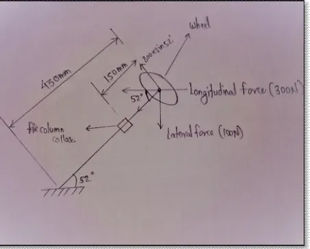
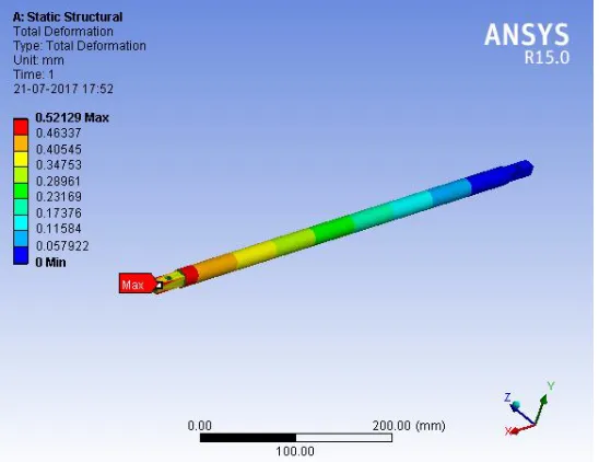
C. Steering Column Analysis for Lateral and Longitudinal Forces
= 124 N/mm2
σb(longituinal) = = 105.92 N/mm2
σb(lateral) = 44.80 N/mm2
σb(longitudinal)and σb(lateral)≤ σt
Therefore, the design is safe.
D. Material and Manufacturing Processes of Different Components.
The material selection and the manufacturing processes involved in the process are as follows;
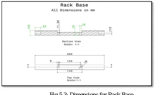
1) Rack: Rack design is of composite material to reduce the weight. It is composition of steel (EN8) and Nylon 6.
Fig 5.3: Dimensions for Rack Base
a) Material selected for Rack plate is bright EN8 steel. We choose EN8 because of its higher wear resistance, strength and low
cost.
b) Material selected for Rack Base is Nylon 6. We choose nylon 6 because it is lighted in weight
c) On the shaft, turning and facing operations were done by lathe machine
d) Holes of M10 were made on both the ends of the rack shaft
e) Milling is done on rack base to make a pocket to fit rack plate in it
f) Milling is also done for making teeth on rack plate
[image:10.612.173.436.437.597.2]Fig 5.4: Draft for Pinion Gear
Fig 5.5 : Pinion Manufactured with the Splines
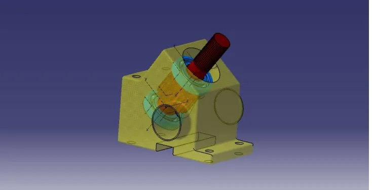
2) Casing
a) Material : The material selected for the manufacturing of rack and pinion casing was Nylon 6. This material was selected by analysing the theoretical and experimental data of material to reduce the weight of component.
[image:11.612.124.491.528.716.2]b) Manufacturing
i) The operation is done on Vertical Milling Centre (VMC) Machine. This machine is selected to reduce the cost and time
required.
Fig 5.7: Structural Analysis of Tie Rod
3) Manufacturing
a) Selected pipe is cut into required number of pieces (two pieces) of same size.
b) Turning and facing operation is done on shaft for bushing on lathe machine.
c) Press fitting of bushes on tie rod ends is done by Hydraulic Press Fitting Machine.
d) Tungsten Inner Gas (TIG) welding is done after press fitting on bushes and pipes of tie rod.
[image:12.612.185.459.124.335.2]
Fig 5.8 : Tie Rods
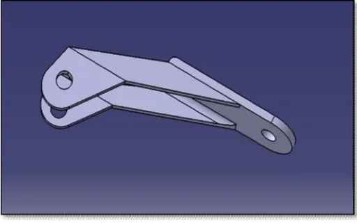
4) Steering Arm
a) Material
The operation is done on Vertical Milling Centre (VMC) Machine. This machine is selected to reduce the cost and time required.
Fig 5.9 : Steering Arm (CAD Model)
5) Nuts And Bolts
a) Nuts and bolts of standard grade and size are purchased with dimensions according to different functions.
6) Bearing
a) Bearing of standard size were selected and also the design of parts is made by considering the size of the bearing. And the size
of bearing is as follows I.D. = 20 mm O.D. = 42 Width = 8 mm
7) Joints: Standard Joint Selected is Heim-joint and it is used on both the ends of Tie Rod. The size of Heim-joint is M8, This Joint is chosen because it has 12 Degree of Freedom and light in weight.
Manufactured U-joint is selected for connecting tie rod and rack. Material selected for it, is EN8. And Manufacturing of this
VI. VALIDATION
A. Rack Travel
1) Steering wheel and pinion were set to the centre position and a marking is made on the rack with a marker.
2) The steering wheel is turned to either of the side to full lock position and then another marking is made at position where
last marking was taken
3) After that the distance between both the markings is measured and the distance between them tell us the rack travel.
B. Turning Radius
1) It is implemented practically by driving the vehicle and measuring the smallest radius the vehicle could turn with the help of
measuring tape.
2) The patches of the wheels helped us in taking the measurements.
3) In static condition it is validated by turning the wheel to full lock condition and then projecting the stub axles of the front
wheels to the rear axle projection.
4) Then the distance is measured between the intersection point and the certain point on the vehicle.
C. Angles turned by the tires
1) The projections of the tire centres were mark on the ground in static straight position of the vehicle.
2) Then the tires were turn to full steer condition and another projection is made on the ground at tire centre.
D. Steering Wheel Rotation
1) Steering wheel rotation is validated by turning the steering wheel from one side to another side full lock positions.
2) The angle turn by the steering wheel is measure and is converted into number of rotations.
E. Ackermann Percentage
1) Angles of tire deviation are measured and it is used to calculate ‘Ackermann Percentage’.
2) Then the theoretical value of Ackermann percentage is compare with practical value.
F. Steering Ratio
1) It is validated by turning the steering wheel to full lock condition to either side.
2) Then the angle by which steering wheel rotates and the angle deviates by the tire is measured.
3) The ratio of degrees of steering wheel rotation to the degrees of tire deviation gives us the steering ratio on which the vehicle is
going to respond.
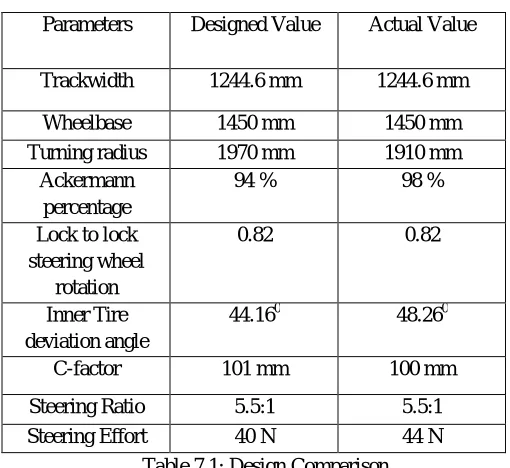
VII. DESIGNCOMPARISONTABLE
[image:14.612.179.434.288.522.2]The difference between the designed value and the actual is due to the errors made in the manufacturing phase or errors due to play or clearances.
Table 7.1: Design Comparison
VIII. CONCLUSION
From the testing phase of the vehicle, we got to know that the designed value of the parameters and the actual value of the parameters are close enough to function without failures and satisfy our required needs. Hence, the designed system works as per the driver input and make the vehicle more responsive to act over the driver’s input and to control it more easily.
IX. ACKNOWLEDGMENT
We are grateful to all those who helped us out to make this article possible. All the efforts taken by the members are remarkable and we will remain obliged to it.
REFERENCES [1] Race car Vehicle Dynamics- Milliken & Milliken
[2] Automobile Engineering by Kirpal Singh [3] Gillespie’s Fundamentals of Vehicle Dynamics. [4] Tune to Win By Carroll Smith
[5] CATIA Software for Designing of Components.
[6] LOTUS Suspension Analysis for Designing the Iterations of the Steering System. [7] ANSYS for various Analysis of all the components.
Parameters Designed Value Actual Value
Trackwidth 1244.6 mm 1244.6 mm
Wheelbase 1450 mm 1450 mm
Turning radius 1970 mm 1910 mm
Ackermann percentage
94 % 98 %
Lock to lock steering wheel
rotation
0.82 0.82
Inner Tire deviation angle
44.160 48.260
C-factor 101 mm 100 mm
Steering Ratio 5.5:1 5.5:1