Abstract—This paper’s main focus is on vertical handover to preserve mobile nodes’ connections in spite of its movement from one network to another heterogeneous network and also provide quality of service factors’ utilization. This vertical handover involves procedures of registration, binding, route optimization, and bi-directional tunneling mode so that transition between heterogeneous access technologies is transparent to user. In this paper we have proposed an algorithm for vertical handover in multi-homed mobile node that relies on received signal strength and threshold along with quality of services factors, where QoS mapping is carried out, and in traffic conditioning block four classes are differentiated and assigned various weights to improve performance and QoS provision. When we simulated network topology with novel multi-homed mobile node, then simulation results shows good network performance where throughput is improved and delays are reduced during vertical handover where it switches all traffic between heterogeneous networks at once.
Index Terms—Vertical Handover; Dual Interface;
Multi-homing; Quality of Service; Heterogeneous Network.
I. INTRODUCTION
Ow-a-days, in heterogeneous network environment wireless network technologies are varying widely on bases of bandwidth, delays, coverage range, power consumption, to name a few. There are wireless networks which provide wide access range but at low transmission rate. On the other hand, we have wireless networks that cover small access areas with higher bandwidth. These different wireless networks are coexisting to complement each other and form a heterogeneous wireless environment in wireless overlay network [1]. Within such a wireless overlay environment, mobile device are equipped with more than one type of network interfaces so that it can connect to different access networks at different locations and time based on user preferences or predefined Quality of Service (QoS) policies. These wireless networks includes pedestrian, a vehicle, a moving train, or an airplane, while moving wireless network are connected to different access networks to provide services to end nodes within its coverage range [2].
Manuscript received March 23, 2011; revised April 16, 2011. Nadia Qasim is researcher with the Center for Telecommunication at King’s College London, Strand WC2R 2LS, London, UK, phone: 02078482889; fax: 02078482664; e-mail: [email protected]. Dr. Muhammad Saleem Sheikh is with Preston University, [email protected]
The switching between these heterogeneous networks with different link-layer is considered as vertical handover [1]. Recently academic researchers and scholars are extensively researching on integrating these two technologies 802.11e and 802.16e in order to provide improvement for QoS over wireless networks [1, 2, 3, 7, and 9], in this paper these two technologies are referred as 11e and 16e, MN is used for multi-homed MN.
II. INTEGRATION MECHANISM FOR HETEROGENEOUS
NETWORK
The effective provision of vertical handover most importantly requires integration and interoperation of heterogeneous networks. Many aspects of both technologies are taken in consideration for architecture integration along with QoS provision. At network layer for address configuration Mobile IPv6 is exercised during wireless network mobility configurations. The vertical handover in these heterogeneous networks is carried out to provide optimisation of performance and provide better QoS after coverage range is switched [5]. Therefore, the limited coverage range of 11e is extended after vertical handover to 16e network and so it meets the need of next generation wireless networks in order to provide “always on” connectivity services anywhere and at any time. As there is significance difference in data rates of these two technologies. Therefore, in order not to affect overall level of network performance, data rates are mapped by QoS differentiation of traffic by various classes. Thus, vertical handover is carried out with no visible disruption in services.
III. VERTICAL HANDOVER MECHANISM THROUGH MULTI
-HOMED MOBILE NODE
In order to carry out vertical handover, we have designed novel multi-homed Mobile Node with dual MAC via the generic integration method of medium access control of 11e and 16e. It provides multi-homing functionality [8]. When there are heterogeneous wireless overlay networks, which requires simultaneously active network, then network discovery procedure is carried out through router advertisements. As a result multi-homed mobile nodes receive active router advertisements and RF measurements such as Received Signal Strength (RSS). When this RSS with threshold decreases considerably then its predefined level at that time handover procedure starts by discovering higher coverage area then its own as ‘link is going down’ (ld). The parameters for these directional handover include RSS with threshold, perceived QoS available bandwidth and network coverage area for current network connection. After vertical handover, MN’s second dual interface is switched on as it completes assignment to new interface with different channels from different RF bands.
Vertical Handover in Wireless Overlay
Networks with Quality of Service Factors
Nadia Qasim, Member
, IAENG,
Muhammad Saleem Sheikh
IV. VERTICAL HANDOVER PROCEDURE
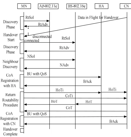
[image:2.595.313.541.51.289.2]The multi-homed MN has more than one wireless network interface in order to communicate via different wireless accesses networks. When a mobile device in 11e domain moves in the new network domain and tries to connect to 16e. As this movement is across different wireless accesses networks vertical handover procedure starts where MN initiates scanning for higher coverage using its dual MAC. We designed signaling framework for vertical handover that is shown in fig 1. In initial discovery phase, MN sends Router Solicitation (RtSol) message of Internet Control Message Protocol (ICMP). This message is multicast by MN over entire network so that network can resume connectivity immediately without the loss of data. These messages are used to inform Home Agent (HA) about its type of services supported by MN and these are not sent periodically. These messages cannot be sent from an inactive interface that is not configured to transmit these messages. When data in flight for handover reaches MN then this handover starts. In discovery phase, AP periodically multicasting Router Advertisements (RtAdv) of ICMP to MN interfaces. These router advertisements announces IP address of current interface in order to know whether MN is on home network domain of 11e or on visited network domain of 16e to determine its Point of Attachment (PoA). These RtAdv have certain lifetime. If MN receives RtAdv, where its lifetime is yet not expired then it means that HA is accessible and is still on home network or vice versa. In neighbor discovery phase, MN sends Neighbor Solicitation (NSol) message to Base Station (BS) which checks if another user may have already manually been assigned same IP address to its MN’s interface through Neighbor Solicitation (NSol) and Neighbor Advertisement (NAdv). In address configuration procedure, MN has moved away from Home Agent (HA) then it acquires a temporary Care-of-Address (CoA) through Dynamic Host Configuration Protocol (DHCP) protocols in CoA registration with HA. There is risk that another user may have been already manually assigned same IP address to its MN’s interface. Therefore, Duplicate Address Detection (DAD) procedure associated with DHCP is carried out in order to check for such duplicate addresses through ICMP Echo request/reply methods. This DHCP server checks for duplication prior to allocating an address to our visiting MN. Then Binding Update (BU) with QoS is send when MN registers its Care-of-Address (CoA) with HA. In response to this, Binding Acknowledgement (BAck) is send to HA from MN. After receiving this Binding Acknowledgement (BA), HA is able to tunnel packets using IP in IP encapsulation from MN’s home address to MN’s new location using CoA. In order to authenticate BU a Return Routability (RR) test is carried out [7]. In RR phase, MN sends two messages of Home Test Init (HoTi) and Care-of Test Init (CoTi) as soon as possible, even at same time. In response to these messages CN reply by sending two messages of Home Test(HOT) and Care-of Test (COT) to MN through HA. During CoA registration with CN phase, optimized path is established where MN sends BU with QoS as replies to these tests directly to CN. Finally, when CN replies with Binding Acknowledgement (BAck) direct to MN, then vertical handover is considered successfully complete.
Fig 1 : Signalling Procedure’s Framework for Vertical Handover
V. VERTICAL HANDOVER END TO END DELAYS
The vertical handover between 11e and 16e includes the preparation time
p
vho
t that comprise of handover preparation time for Layer 2 and Layer 3 with current network Point of Attachment (PoA). This Layer 2 preparation time tL2pdoes not include scanning time for candidate PoA that is base station tL2p−s c nas scanning is carried out on different network interface and
t
vhotime is typically required for Layer 3 handover because target PoA can not be on same subnet of previous PoA that is access point.2 p
v h o L p v h o
t = t +t (1) The vertical handover to 16e includes times after Layer 2 handover excluding scanning time but includes synchronization and ranging, quality of services, key exchange as in authorization, and registration times.
t
vho=
t
L2−scn+
t
syn+
t
qos+
t
auth+
t
reg (2) The vertical handover delay time compose of various delays, which all together make total delays. The collective delays are described in [10]. The movement detection delaym d
∂ is time interval when MN finishes L2 handover
2
L f
t and receives first RA
t
ra.∂md=tL f2 −tra (3) The care of address configuration delay
∂
coa is time interval for receiving first RA by MNt
raand sending time of first BU from MN to HAt
BU.∂coa =
t
ra −t
BU (4) The home agent registration delay ∂regis time interval from MN sends first BU to HAt
BUand MN receives first BA from HAtBA.∂reg = H A B A
t −
HA
BU
Then there is route optimisation delay
∂
roof time interval between MN sends first BU to CNCN
BU
t and MN receives BA from CN
CN
BA
t
.
∂
ro =CN
BU
t
−CN BA
t (6)
Therefore, collectively function of handover delay time of L3 handover consists of summation of all these delays.
F (x) =
∂
md +∂
coa +∂
reg+∂
ro (7)VI. VERTICAL HANDOVER ALGORITHM WITH QOS
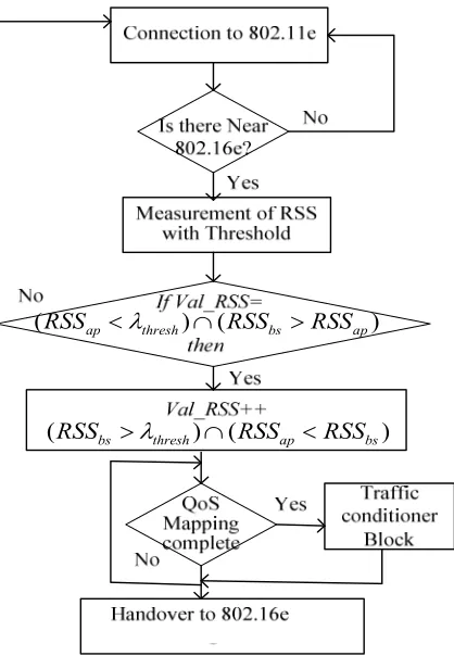
In this paper we have proposed algorithm for upward vertical handover that is carried out at a multi-homed MN for handing over traffic from 11e network to 16e network. The fig (2) demonstrates comprehensive state diagram of algorithm for vertical handover. This handover is initiated through monitoring and comparing RSS with threshold of current connection to signals received from neighboring BS, and it makes decision of vertical handover depending on RSS with threshold profiles of two signals over heterogeneous networks. When MN enters in overlapping network domain than current value of Val_RSS is compared through intersection whether RSS received from AP are less then threshold and RSS received from BS are greater then RSS received from AP. If result is no then it stay connected to 11e network or if yes then it increment the value of Val_RSS, where RSS received from BS are greater then threshold and RSS received from AP are less RSS received from BS. Then QoS mapping is carried out which is explained in later section of paper, after this vertical handover is completed.
(RSSap <
λ
thresh)∩(RSSbs >RSSap) [image:3.595.323.547.350.417.2](
RSS
bs>
λ
thresh)
∩
(
RSS
ap<
RSS
bs)
Fig 2 : Algorithm for Vertical Handover
VII. VERTICAL HANDOVER QOS MECHANISM
This vertical handover is implemented with QoS mechanism in order to improve performance of network. In order to provide this comprehensive QoS mechanism, we carried out mapping between QoS parameters of 11e and 16e networks by specifying level of QoS in its streams as these networks uses different parameters. There are four traffic classes in 11e as voice, video, background and best effort. Whereas there are four types of data delivery services in 16e firstly as Unsolicited Grant Service (UGS) which is used for applications that periodically generates fixed-size packets, secondly as Real-Time Polling Service (rt-PS) which is used for applications requiring guaranteed data rate and delay, thirdly as Non-Real-Time Polling Service (nrt-PS) which is used for applications that require guaranteed data rate but are insensitive to delays, and fourthly as Best Effort (BE) which is used for best effort traffic with no guarantees of data rate or delays [4]. When we carry out mapping, these four classes and services are mapped to Constant Bit Rate (CBR), Real Time Variable Bit Rate (rt-VBR), Non Real Time Variable Bit Rate (nrt-VBR) and Minimum Guarantee Best Effort (MGBE) [2]. The traffic based on each class priority is forwarded to separate queues of Class Based Weighted Frequency Queuing (CB-WFQ). This QoS mapping between traffic classes of 11e and 16e is shown in following Table I.
TABLE I. QOS MAPPING TABLE
802.11e 802.16e QoS Mapping Classes
Voice UGS CBR
Video rt-PS rt-VBR
Background nrt-PS nrt-VBR
Best Effort BE MGBE
[image:3.595.74.283.430.732.2]For this QoS mechanism we exploit Traffic Conditioner Block (TCB) of Differentiated Service’s (DiffServ). This quality of services by traffic conditioner block is shown in fig (3). In TCB, when packets arrive at classifiers where its task is to separate on coming submitted traffic into four different classes. The Per Hop Behaviour (PHB) associated with Differentiated Service Code Point (DSCP) in its packet header to forwards packets that have arrived according to its prioritization.
[image:3.595.320.543.559.750.2]Then these mapped packets of CBR, rt-VBR, nrt-VBR and MGBE through traffic identification are forward to appropriate priority queues. Marking incoming traffic flows carries out prioritizing incoming traffic to prevent collisions and delays. The high priority traffics with demanding requirements are given special treatments. The network traffic resources are assigned bandwidth according to management policy criteria. For this management we have assigned weights to queues as 25%, 50 %, 15%, 5% to incoming traffics flows of CBR, rt-VBR, nrt-VBR and MGBE respectively. The values for each four queues are important for determining extent of service differentiation in EDCA to maximize throughput of our network. The conditioner block in TCB has shapers and dropper. The shapers delay some or all of packets in traffic stream in order to compliance traffic profile and queuing packets in a finite-sized buffer of CB-WFQ achieve this shaping. Whereas in droppers some of packets are dropped if it exceeds rate specified in its profile. The traffic load is generated by application and associated QoS requirements are stored in application profile. The guarantees of assured bandwidth to one of four Assured Forwarding (AF) classes are carried out where each class is allowed up to 3-drop possibilities and is then provided further bandwidth, if available to provide throughput according to priority of classes.
VIII. VERTICAL HANDOVER DUAL MAC LAYER
In our QoS context, the Hybrid Coordination Function (HCF) mechanism of MAC layer is utilized to provide QoS with various bandwidth weights to various real time and non real time traffic classes. The HCF has two medium access modes such as Enhanced Distributed Channel Access (EDCA) and HCF Controlled Channel Access (HCCA) [6]. We have applied EDCA to Differentiated Service’s (DiffServ) flow controls. These differentiations are provided when nodes experience same channel conditions. The 11e provides prioritized media access and Enhanced Distributed Channel Access (EDCA) method is used in our network. This EDCA has contention parameters of Arbitration Inter Frame Space (AIFS), persistence factor (PF), and Transmission Opportunity (TxOp), CWmin and CWmax parameters. In our MAC layer queue structure in EDCA has four queues. Each of four queues has buffer and forwards data from four traffic classes respectively and we have labeled these queues as Qc0, Qc1, Qc2, and Qc3. The priority is from Qc0, which is highest, towards Qc3, which is lowest priority. All these four queues have its own contention parameters of AIFS, Persistence factor, TxOp, CWmin and CWmax. These parameters are announced in beacons to allow the network to use the mapped parameters and contend fairly for TXOPs.
In our dual MAC layer, let βi is the number of backoff slots involving the Binary Exponential Backoff (BEB) and AIFS by multi-homed MN during transmission and these transmission packets are ready at the head of transmission queue [7] that is approximated by following equation.
lim( ( ( ) 0) 1 0
1 1 1
s r i
t i
i
i i i
P Q t η ρ
ξ
β β β
→∞ > −
= = =
+ + +
(8)
Whereas βi includes the blocked slots for each AIFS interval and average number of backoff slots selected at each transmission attempt, EBi is average number of exponential
backoff slots selected by multi-homed node i at each transmission attempt in a random slot for ready packet in transmission queue. As exponential backoff and conditional collision probability isρi and Qiis QoS at i, t is time. Let s
η
the equilibrium distribution, the departure probability is / (1 i)
d s s
K
η =η −η [7]. Then EBi is given as
1 (2 ) min, 1
1 2 2 2
i m i i i i i CW
EB ρ ρ ρ
ρ
− −
= −
−
(9)
Moreover, the service time consists of time interval when packet enters in service till it is transmitted or discarded over network as shown in following equation
, || / || /
, ,
(
1)(
)
ii b ba rts cts
b ba rts cts
i i i i c i i i s i
X
=
M
−
β γ
+
ET
+
β γ
+
ET
(10)In this equation M i is average number of transmissions by multi-homed mobile node i, , || /
,
i
b b a r t s c t s s i
E T is successful
average duration of a transmission of EBi packets burst transmission using binding acknowledgement BA or request to send or clear to send (RTS/CTS) access mechanism, γi is average duration in slot, || /
,
ba rts cts c i
ET is average duration of collision of multi-homed mobile node i.
IX. SIMULATION RESULTS AND ANALYSIS
The simulation environment consists of multi-homed mobile node (MN) and correspondent node (CN) which are placed in different 11e and 16e coverage area and these are placed uniformly and forming a wireless heterogeneous network, moving over 1 km area for 170 seconds of simulated time. There are also configured home agent (HA), access point (AP) and base station (BS) in this wireless overlay network. This simulation is conducted in OPNET™ 15.0, as it is very fast event simulating engine. Following Table II shows various parameters used during this simulations’ execution.
TABLE II. PARAMETERS FOR SIMULATION
Parameters Value
Node MAC Type Multi-homed MAC with
integrated 11e and 16e MAC
Multipath Channel Model ITU Pedestrian A Packet Reception Threshold 95 dBm
AP Beacon Interval 0.02
Router Solicitations Interval Uniform (4.0,4.5) Neighbour Solicitations Interval Uniform(1000,1500) Binding Update Timeout Interval 10 sec
Return Routibility Test Timeout Interval
2 sec
Routing Buffer Size 256,000 bits
Mobility Detection Factor 3
Node Handover Retransmission Timer
30 millisecond
Max Handover Request
Transmission
6
Hybrid Coordination Function - HCF
Supported
Internet cloud is used to abstract the part of network that exists between AP and BS and which is not a point of interest in our simulation. We have tuned different wireless channels for AP and BS and radio coverage is made partially overlapped for AP and BS. In these overlap areas, multi-homed MN is able to conduct successful vertical handover to associate with new POA, and acquire CoA then MN interfaces is switched to 16e network.
Fig 4 : Vertical Handover Simulation Scenario
[image:5.595.46.292.145.335.2]The contention parameters of EDCA are set to default values during simulation. When simulation is carried out it is observed that multi-homed mobile nodes’ MAC is carrier sensing and its backoff mechanisms are working accurately. In our network topology, in order to identify current location and maintain mobility over heterogeneous wireless network; MN is configured with multiple IP addresses on its interfaces. These interfaces are handling real time traffic towards CN efficiently by swapping IP and MAC addresses. This multi-homed MN dynamically carries out interface selection on bases of vertical handover metrics and moves all traffic from 11e interface to 16e interface at once. It is able to use all of available connections, as competent usage of connections requires QoS prioritization of incoming traffic in access networks.
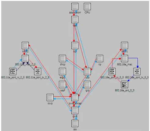
Fig 5 : Multi-Homed Mobile Node Scenario in Node Editor
The fig (5) shows dual multi-homed MAC in node editor of simulator. This implementation of dual medium access control mechanism provides desired QoS without compromising on utilization of medium and without affecting fairness. This dual MAC node manages two buffers, control buffer and data buffer. This dual MAC node buffers data during its scanning and during vertical handover time. For scanning, the serving AP multicast MN_RtAdv message to provide network topology with information about of its current IP address in MN. The serving AP buffers data for a MN during scanning and forward buffered data to the MN after finishing scanning. MN measures received signal strength and reports it to serving AP. When it falls is below predefined threshold TH1 then vertical
handover starts. Then MN synchronizes with the candidate neighbor BS and gathers channel information via scanning process. To scan neighbor BS, a MN sends MN_NBR_SOL_REQ message in response MN receives MN_NBR_ADV_REP message from BS. Then MN_BU-REQ and MN_BU-REP with QoS information are communicated then binding of care of address with HA is carried out. A MN is allocated Channel Identification CID and RR procedure is also carried out. The final step in vertical handover, where MN is directly connected to CN and where serving AP terminates context of MN as after handover MN is serviced by BS on receiving CN_BU-REP message on response to CN_BU-REQ message.
X. SIMULATION RESULTS
A. Vertical Handover Throughput Results
The simulation results of throughput are shown in following fig (6) where throughput is total number of bits per second received by destination. During simulation, when MN and CN’s connection is established then total throughput mainly fluctuates around 700 Kbps over total simulation time of 170 seconds. We observed that at beginning of simulation until 75 seconds MN is connected to 11e. After 76 seconds, throughput falls very sharply to 696.8 Kbps for short period of time, as it is caring out vertical handover procedure of registration, binding, route optimization, and bi-directional tunnel between two access technologies.
0 20 40 60 80 100 120 140 160
695 696 697 698 699 700 701 702
Simulation Time (s)
T
h
ro
u
g
h
p
u
t
(K
b
p
[image:5.595.45.291.547.762.2]s)
Fig 6 : Throughtput Mobile Node
Home Agent Access Point
Next Generation Internet Base Station
Correspondent Node Trajectories
Boundary of 11e Domain
0 20 40 60 80 100 120 140 160 0
0.05 0.1 0.15 0.2 0.25 0.3 0.35 0.4 0.45 0.5
Simulation Time (s)
E
n
d
-t
o
-E
n
d
D
el
ay
(
[image:6.595.62.289.62.296.2]s)
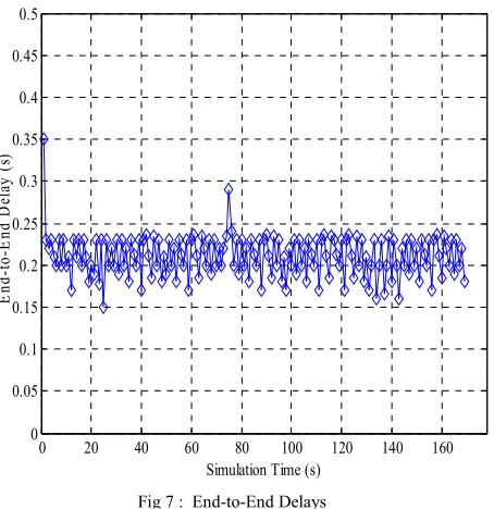
Fig 7 : End-to-End Delays
B. Vertical Handover End-To-End Delay Results In this simulation, end-to-end delays are shown in fig (7). This graph shows that these delays mainly fluctuate around 0.18 and 0.24 seconds. In middle of simulation, we observed abrupt delays of around 0.29 seconds in access network, which is because as MN switches its interface and carries out vertical handover.
XI. CONCLUSION
We have considered managing link layer resources and mapping of QoS traffic classes in application profiles, channels, interfaces and managing the time-varying network conditions. In our vertical handover algorithm, its decision is based on link quality measurements such as received signal strength with threshold and QoS through traffic conditioner block where classes are assigned various weights for prioritization of ingress traffic in differentiated service’s manner to improve network efficiency. The simulation results show that there is good network performance in terms of throughput and end-to-end delay. It is observed that there is fair increase in network throughput as it has acquired quality of service and maintains connectivity in wireless overlay networks. There is reduction in end-to-end delay based on quality of transmission in real-time traffic such as voice and video and non real-time traffic over heterogonous networks. Hence, the overall performance of wireless overlay networks has improved during vertical handover.
REFERENCES
[1] K. Andersson, C. Ahlund, B. Sharma Gukhool, and S. Cherkaoui, Mobility management for highly mobile users and vehicular networks in heterogeneous environments, In Proceedings of the 33rd IEEE Conference on Local Computer Networks (LCN'08), Montreal, Canada, October 2008.
[2] Y. Chen, J. Hsia, Y. Liao, Advanced seamless vertical handoff architecture for WiMAX and WiFi heterogeneous networks with QoS guarantees, Elsevier Journal Computer Communications, vol 32, pg 281-293, 2009.
[3] K. Andersson, A. Zaheduzzaman Sarker, C. Ahlund, Multihomed Mobile IPv6: OPNET Simulation of Network Selection and Handover Timing in Heterogeneous Networking Environments, In Proceedings of The Eleventh Annual OPNET Technology Conference (OPNETWORK 2007), Washington D.C., USA, August 2007.
[4] C. Cicconetti, L. Lenzini, E. Mingozzi, C. Eklund, Quality of service support in IEEE 802.16 networks, IEEE Network 20(2): 50-55, 2006. [5] M. Bernaschi, F. Cacace, G. Iannello, Vertical handoff performance in heterogeneous networks, 32nd IEEE Conference on Local Computer Networks, pp. 703-710, 2004.
[6] B. Bellalta, Flow-level QoS guarantees in IEEE 802.11e-EDCA based WLANs, Thesis, Universitat Pompeu Fabra, ISBN: 978-84-690-7820-4, December 2006.
[7] M. Stemm, Randy H. Katz, Vertical handoffs in wireless overlay networks, Mobile Networks and Applications, vol. 3, pp. 7-80, 1999. [8] V.S. Kaulgud, S.A. Mondal, Exploiting multihoming for low latency
handoff in heterogeneous networks, 8th International Conference Telecommunications, vol. 1, pp. 49-55, 2005.
[9] M. Li, K. Sandrasegaran, T. Tung, “A Multi-Interface proposal for IEEE 802.21 media independent handover”, Sixth international conference on the management of mobile business, 2007.
[10] G. Xie, J. Chen , H. Zheng, J. Yang, Y. Zhang, “Handover Latency of MIPv6 Implementation in Linux”, Proceedings of IEEE GLOBECOM, 2007.