http://wrap.warwick.ac.uk
Original citation:
Ahmad, Mussawar, Ahmad, Bilal, Alkan, Bugra, Vera, Daniel, Harrison, Robert,
Meredith, James O. and Bindel, Axel (2016) Hydrogen fuel cell pick and place assembly
systems : Heuristic evaluation of reconfigurability and suitability. In: 49th CIRP
Conference on Manufacturing Systems (CIRP-CMS 2016), Stuttgart, Germany, 25-27
May 2016. Published in: Procedia CIRP pp. 1-6. (In Press)
Permanent WRAP url:
http://wrap.warwick.ac.uk/77844
Copyright and reuse:
The Warwick Research Archive Portal (WRAP) makes this work of researchers of the
University of Warwick available open access under the following conditions.
This article is made available under the Creative Commons
Attribution-NonCommercial-NoDerivatives 4.0 International (CC BY-NC-ND 4.0) and may be reused according to the
conditions of the license. For more details see
http://creativecommons.org/licenses/by-nc-nd/4.0/
A note on versions:
The version presented in WRAP is the published version, or, version of record, and may
be cited as it appears here.
ScienceDirect
Procedia CIRP 00 (2016) 000–000
www.elsevier.com/locate/procedia
2212-8271 © 2016 The Authors. Published by Elsevier B.V.
Peer-review under responsibility of Scientific committee of the 49th CIRP Conference on Manufacturing Systems (CIRP-CMS 2016).
49th CIRP Conference on Manufacturing Systems (CIRP-CMS 2016)
Hydrogen fuel cell pick and place assembly systems: Heuristic evaluation
of reconfigurability and suitability
Mussawar Ahmad
a*, Bilal Ahmad
a, Bugra Alkan
a, Daniel Vera
a, Robert Harrison
a,
James Meredith
b, Axel Bindel
c,
aAutomation Systems Group, WMG, University of Warwick, CV4 7AL, Coventry, West Midlands, UK bMechanical Engineering, University of Sheffield, South Yorkshire, S10 2TN
cHSSMI, Queen Elizabeth Park, London, E20 3BS
* Corresponding author. Tel.: +44 (0) 2476 573413;. E-mail address: [email protected]
Abstract
Proton Exchange Membrane Fuel Cells (PEMFCs) offer numerous advantages over combustion technology but they remain economically uncompetitive except for in niche applications. A portion of this cost is attributed to a lack of assembly expertise and the associated risks. To solve this problem, this research investigates the assembly systems that do exist for this product and systematically decomposes them into their constituent components to evaluate reconfigurability and suitability to product. A novel method and set of criteria are used for evaluation taking inspiration from heuristic approaches for evaluating manufacturing system complexity. It is proposed that this can be used as a support tool at the design stage to meet the needs of the product while having the capability to accept potential design changes and variants for products beyond the case study presented in this work. It is hoped this work develops a new means to support in the design of reconfigurable systems and form the foundation for fuel cell assembly best practice, allowing this technology to reduce in cost and find its way into a commercial space.
© 2015 The Authors. Published by Elsevier B.V.
Peer-review under responsibility of Scientific committee of the 49th CIRP Conference on Manufacturing Systems (CIRP-CMS 2016).
Keywords: Reconfigurability; hydrogen fuel cells; pick and place; assembly
1.Introduction
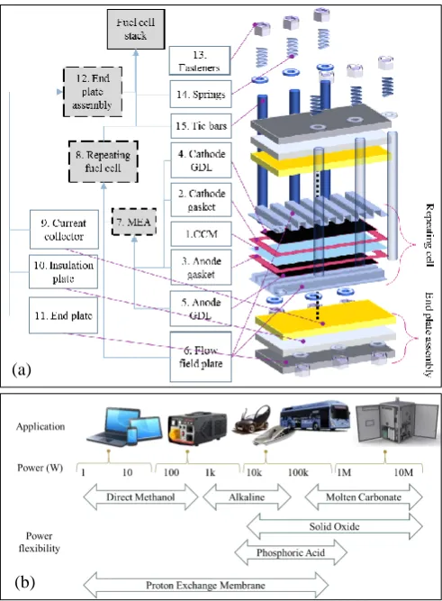
Climate change and human health concerns associated with the combustion of fossil fuels are putting increased pressure on industry to develop and implement more efficient, less polluting power generation and storage technologies. One such technology is the hydrogen fuel cell, an electrochemical device that generates electricity and produces water as the only emission (Fig. 1a). Despite its benefits the fuel cell costs remain at least an order of magnitude greater [1, 2] than targets that would allow it to compete with internal combustion engines i.e.
30$/kW-50$/kW [3, 4]. These higher costs are attributed to: inadequate product durability, expensive component materials, and immature manufacturing and final assembly methods. Methods and considerations for fuel cell product assembly are limited in the literature. The author believes that this lack of exploration into manufacturing assembly strategies and systems are one of the key barriers to more widespread commercialization of this technology. It is important for a fuel
2 Author name / Procedia CIRP 00 (2016) 000–000
2.Review of literature
2.1.Defining reconfigurability
The concept of reconfigurable manufacturing systems (RMS) has been defined in a number of different ways. Koren describes it as a system that, at the outset, is designed for a change in structure both from a hardware and software perspective [5]. Makino and Trai focus on the geometric setup changeability and describe reconfiguration as a characteristic of flexible assembly systems, categorizing them into statically and dynamically reconfigurable [7]. Lee defines reconfigurability as the ability to economically reconfigure a system, however there was also a focus to design a product such that reconfiguration was minimized [8]. Furthermore, concepts similar to that of reconfigurability have been proposed using alternative terminology such as ‘evolvable’, ‘holonic’, ‘modular manufacturing’, ‘component-based manufacturing’ and more [9]. However, the common objectives of all of the research in this area is to accommodate change and quickly react to uncertainty both within the system and externally [10].
2.2.Reconfigurable assembly systems (RAS)
The enabling technologies for RASs are [11]: 1) modular manufacturing system equipment and distributed control [12], and 2) methods that facilitate rapid system re/design and re/deployment [6, 11]. The objective of an assembly system is to realise every part liaison to a given specification to form either a sub-assembly or final assembly. While a dedicated system meets this objective for a given product, the RAS is designed to accommodate a product family and product design changes (customization), introduction of new process technologies (convertibility) and volume fluctuations (scalability) using functionality embedded into ‘plug and play’ components (modularity, integrability) in a maintainable way (diagnosability)to facilitate the paradigm shift away from mass production and towards mass customization [5, 12]. Comprehensive reviews of flexible and reconfigurable assembly systems are presented in [7, 12]. The differentiation between these systems is that the former has general flexibility, whereby the system can produce almost any product that can fit on the machine, which is not true for RAS [13]. The literature identifies the following as core components of an RAS [7, 10, 12, 14, 15]:
Mechanisms for transferring parts within and across stations that have a flexible level of reachability and can quickly adapt to changes in positional requirements
Jigs, fixtures and clamps for holding parts during processes and transport that are designed with a part/product family in mind with adaptable features to support alignment and holding
Buffering and storage systems to hold parts prior to being introduced into the system that have positional changeability
Feeding mechanisms to transfer parts from storage to be processed that have positional changeability
Gripping or manipulation tools to handle parts that have changeable functionality due to inherent modularity
and that efficiently integrate with the moving mechanism
2.3.Design evaluation of RAS
Evaluation of an RAS at the design stage is essential to determine the nature, degree and appropriateness of the reconfigurability. A design structure matrix was used to assess the reconfigurability of a distributed manufacturing system using the nature and number of interactions of manufacturing system components to allow the designer to identify where the interactions are greatest, from which a lack of modularity and thus reconfigurability can be inferred [15]. A convertibility measure that considered configuration, machine and material handling convertibility produced numerical values generated in part from quantifiable features and in part from a series of questions to identify the nature of the system allowed comparison of system designs at the early system design phase [16]. Several fuzzy approaches are present in the literature that measure system flexibility identifying criteria and rules that lend themselves to measuring reconfigurability [17-19]. Koste et al. presented an approach to measuring manufacturing flexibility by identifying key dimensions of flexibility and use Churchill’s paradigm [20] to demonstrate the weighting that can be given to these metrics (some of which are shared by
Figure 1 (a) Fuel cell and bill of assembly (b) Application of various fuel cell types
[image:3.595.307.553.66.400.2]RAS) based on the experience and expertise of industry [21]. Finally, the application of complexity theory to heuristically compare system designs can be adapted to measure reconfigurability, using a framework that considers the diversity and quantity of information associated with system components, and the information content [22].
2.4.Summary
Reconfigurability is a paradigm of manufacturing systems to accommodate rapid change and fits into the larger, enterprise level concept of agility [23]. This is enabled by technologies such as modular system components and distributed control. However, the literature presents limited means of measuring reconfigurability to assess a system at the design stage, and there is also a lack of assessment on how suitable a given approach is to the needs of the product. Thus, the aim of this piece of research is to propose a methodology to measure, compare and characterize an RAS using the criteria and characteristics identified in the literature
3.Methodology
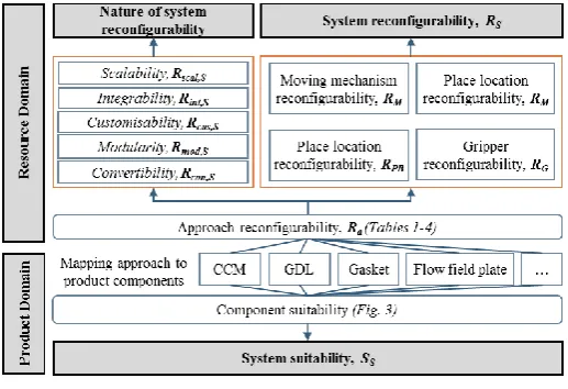
An overview of the approach used in this paper is presented in Fig. 2. The objective of this work is to describe and test a framework which measures the reconfigurability of a RAS and assesses it’s suitability to a product. This is envisioned to be a design support tool and supports system designers in determining whether a proposed system design is sufficiently reconfigurable.
3.1.Reconfigurability
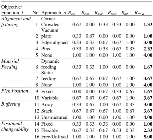
The RAS, S, in this research is assumed to be composed of four elements, i, amalgamated from those identified in the literature: (1) pick and buffer location, EPB (2) gripper, EG(3) moving mechanism, EM and (4) place location, EPL. Each element has a set of functions or objectives, f, and each of these has a set of approaches, a. For each approach, the criteria, C, of reconfigurability, R, are applied: customizability, Rcus, convertibility, Rcon, scalability, Rscal, modularity, Rmod and integrability, Rint. Although the approach to meet an objective or function does not intrinsically hold any information about reconfigurability, this is inferred based on empirical observation and experience. Diagnosability is not assessed due to a lack of available data, however future work could look at how this could be inferred from the criteria measured. The approaches are assigned a value for each of the criteria: 0 = does not meet criterion, 0.33 = some degree of criterion conformity, 0.67 = good criterion conformity, and 1 = strong criterion conformity (Table 1-4) such that:
𝑅𝑎= ∑[𝑅𝑐𝑢𝑠,𝑎, 𝑅𝑐𝑜𝑛,𝑎, 𝑅𝑠𝑐𝑎𝑙,𝑎, 𝑅𝑚𝑜𝑑,𝑎, 𝑅𝑖𝑛𝑡,𝑎] Eq. 1
The reconfigurability of a function in an element is given by Eq. 2:
𝑅𝑓 = 𝑁𝑐𝑜𝑚𝑝,𝑎× 𝑅𝑎,𝑓 Eq.2
Where Ncomp is the number of components. The reconfigurability of an element in a system is given by Eq. 3:
𝑅𝑖= (∑ 𝑅𝑓,𝑖
𝑁𝑓𝑢𝑛𝑐
𝑖=1 ) ÷ 𝑁𝑓𝑢𝑛𝑐,𝑖 Eq. 3
Where Nfunc,i is the number of functions in an element. By dividing by the number of functions for a given element, the approach penalizes excessive functionality as this would make each element complex and less likely to be reconfigurable. The system reconfigurability is given by Eq. 4
𝑅𝑆=
∑𝑁𝑒𝑙𝑒𝑚𝑖=1 𝑅𝑖,𝑆
𝑁𝑒𝑙𝑒𝑚,𝑆 Eq. 4
Where Nelem is the number of elements. In this research this value is always four. The nature of the reconfigurability of the element is determined by calculating a component quantity relative value for each criteria (Eq.5):
𝑅𝐶,𝑖=
𝑁𝑐𝑜𝑚𝑝,𝑎×𝑅𝐶,𝑎
𝑁𝑐𝑜𝑚𝑝,𝑖 Eq. 5
Then at the system level, the nature of reconfigurability is given by Eq. 6:
𝑅𝐶,𝑆= ∑𝑁𝑖=1𝑒𝑙𝑒𝑚𝑅𝐶,𝑖 Eq. 6
3.2.Suitability
System suitability, K, to product has been assessed by abstracting product component characteristics that are perceived to impact material handling. Another important consideration regarding the product is the nature of the liaisons between the components, however this is not considered in this research. As the case study focuses on hydrogen fuel cell assembly, only the characteristics of fuel cell components (Fig 1a) that could affect material handling are introduced. The mapping of the components to the approaches of the system are presented in Fig. 3. Three characteristics are used to facilitate the mapping: flexibility, brittleness and porosity. Flexibility dictates the level of mechanical support required by the pick and place system to prevent component deformation. Brittleness refers to how much and the type of force that can be applied to the component to avoid damage. Porosity helps to inform the type of gripper that can be used on the component
[image:4.595.309.568.70.247.2]i.e. thin porous stacked components do not lend themselves to vacuum grippers, unless an additional level of control is added. With appropriately abstracted features of system component
4 Author name / Procedia CIRP 00 (2016) 000–000
approaches, a rule based approach could be used to automatically map product component characteristics to system component capabilities. The element that is not considered for suitability in this approach is the moving mechanism as it has no physical interaction with the product components. Furthermore certain functions within other elements have limited impact on material handling and so are not considered. A given approach is assigned the following value, based on the product characteristics: 0 = unsuitable (no mapping), 1 = acceptable but has an element of risk i.e.
potential to damage component, or approach is excessively sophisticated (dashed line) and 2 = suitable approach (solid line). The suitability of a given approach, Ka, is calculated by summing the suitability values of the product for that approach multiplied by the number of suitable components of that approach. For the element, Ki, the suitability of all approaches are summed and for the system, Ks, the suitability of all elements are summed and log10 applied to better compare the
large values generated. This is a coarse approach to assessing product suitability, however as all systems are subjected to the same method it does allow an evaluation to be made. Furthermore, the reconfigurability of a system can be compared with suitability and conclusions can be drawn about the impacts they have on each other.
4.Case study – Fuel cell pick and place systems
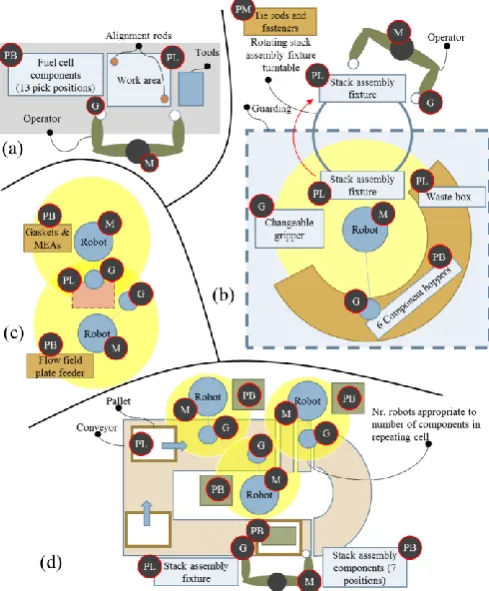
The case study explores four fuel cell assembly systems. The first is a manual approach (a) [24] (Fig.4a), the second is semi-automated (b) [25] (Fig.4b), the third is a fully automated system (c) [26] (Fig. 4c) and the fourth is a conceptual assembly system that has been designed with reconfigurability in mind (d) (Fig. 4d). The first three systems are used to test the method for measuring reconfigurability, without these any hypotheses cannot be tested as the systems cannot be
Objective/
Function, f Nr Approach, a Rcus Rcon Rscal Rmod Rint RM,a
Moving mechanism
32 6 DOF robot 1.00 1.00 0.67 0.00 0.00 2.67
33 4 DOF robot (SCARA) 0.67 0.67 1.00 0.33 0.33 3.00
34 1-3 axis gantry 0.67 0.33 1.00 0.67 0.67 3.33
35 Rotary table 0.33 0.33 0.33 0.67 1.00 2.67
36 Conveyor 0.67 0.33 0.67 0.33 0.67 2.67
37 AGV 1.00 1.00 0.67 1.00 1.00 4.67
38 Human 1.00 1.00 1.00 1.00 1.00 5.00
Reach and work area
39 Tight 0.00 0.00 1.00 0.33 0.33 1.67
40 Appropriate to application 0.33 0.33 0.33 0.00 0.00 1.00
41 Large relative to application 0.67 1.00 0.33 0.00 0.00 2.00
Positional changeability
43 Fixed 0.33 0.33 0.33 0.00 0.00 1.00
44 Flexible 0.67 0.33 0.67 0.33 0.33 2.33
45 Free/Unfixed 1.00 1.00 1.00 1.00 1.00 5.00
Objective/
Function, f Nr Approach, a Rcus Rcon Rscal Rmod Rint RPL,a
Place position check
46 None 1.00 1.00 1.00 1.00 1.00 1.00
47 Manual 1.00 1.00 0.33 1.00 1.00 0.87
48 Passive 0.33 0.33 0.67 0.33 0.33 0.40
49 Active 0.67 1.00 0.33 0.00 0.00 0.40
Place position 50 Fixed 0.00 0.00 0.67 0.67 1.00 0.47
51 variable 0.67 0.67 0.67 0.33 0.33 0.53
Positional changeability
52 Fixed 0.33 0.33 0.33 0.00 0.00 0.20
53 Flexible 0.67 0.33 0.67 0.33 0.33 0.47
54 Free/Unfixed 1.00 1.00 1.00 1.00 1.00 1.00
Objective/
Function, f Nr Approach, aRcus Rcon Rscal Rmod Rint RPB,a
Alignment and
fixturing 1
Corner
Crowded 0.67 0.00 0.33 0.33 0.00 1.33
2 Vacuum
plate 0.33 0.67 0.00 0.00 0.00 1.00
3 Edge aligned 0.33 0.33 0.67 0.67 1.00 3.00
4 Pins 0.33 0.67 0.33 0.67 0.33 2.33
5 None 1.00 1.00 0.00 1.00 1.00 4.00
Material
Feeding 6
Dynamic
feeding 0.33 0.33 1.00 0.00 0.00 1.67
7 Static
feeding 0.67 0.67 0.67 0.67 1.00 3.67
8 None 1.00 1.00 0.00 1.00 1.00 4.00
Pick Position 9 Fixed 0.00 0.00 0.67 0.33 0.67 1.67
10 Variable 0.67 0.67 0.67 0.67 1.00 3.67
Buffering 11 Array 0.33 0.67 1.00 0.67 0.33 3.00
12 Stack 0.67 0.67 0.67 1.00 0.67 3.67
13 Unstructured 1.00 1.00 0.00 1.00 1.00 4.00
Positional changeability
14 Fixed 0.33 0.33 0.33 0.00 0.00 1.00
15 Flexible 0.67 0.33 0.67 0.33 0.33 2.33
[image:5.595.307.571.76.264.2]16 Free/Unfixed 1.00 1.00 1.00 1.00 1.00 5.00
[image:5.595.305.571.284.440.2]Table 1 Place position reconfigurability, RPB,a
Figure 3 Suitability Mapping
Objective/
Function, f Nr Approach, a Rcus Rcon Rscal Rmod Rint RG,a
Component gripping
17 Vacuum cup single 1.00 0.33 0.67 0.67 0.67 3.33
18 Vacuum cup array 0.67 0.67 0.67 0.33 0.33 2.67
19 Vacuum plate 1.00 0.67 0.33 0.67 0.33 3.00
20 Pneumatic
mechanical 0.67 0.67 0.67 0.67 0.67 3.33
21 Electric mechanical 1.00 1.00 0.67 0.67 0.67 4.00
22 Human hand 1.00 1.00 1.00 1.00 1.00 5.00
Gripper DoF 23 0 0.00 0.00 0.67 1.00 1.00 2.67
24 1-2 0.33 0.33 0.33 0.67 0.67 2.33
25 >2 0.67 1.00 0.67 0.33 0.00 2.67
Relation with moving mechanism
26 Operator interaction 1.00 1.00 0.67 1.00 1.00 4.67
27 Semi-auto 0.67 0.67 1.00 1.00 0.67 4.00
28 Automated 0.33 0.33 0.67 0.33 0.33 2.00
Control 29 Binary 0.33 0.00 1.00 0.67 0.67 2.67
30 Variable set point 1.00 1.00 0.33 0.33 0.33 3.00
[image:5.595.38.284.288.516.2]31 Manual 1.00 1.00 0.67 1.00 1.00 4.67
[image:5.595.305.566.466.577.2]Table 2 Gripper reconfigurability, RG,a
Table 3 Moving mechanism reconfigurability, RM,a
[image:5.595.35.279.554.778.2]compared. The case study also compares the suitability of the four systems to assemble the fuel cell product presented in Fig. 2a. As geometry is not a criteria presented in the product characteristics metric, the suitability is therefore an abstract measure to check how well those characteristics that have been defined map to the assembly system components.
4.1.Case study system descriptions
The manual system (a) uses only an operator to pick all components from unsupported component stacks and fed onto a pin aligned moveable jig. The semi-automated (b) system uses a large robot to place components from corner crowded hoppers onto a stack assembly fixture. Due to the delicate nature of one of the components, spacers have been placed between them. This adds an additional “false” place position denoted by d3 in Fig. 3c. The stack assembly fixture is rotated twice, first to allow the operator to add some components and then to allow the robot to finish the assembly by changing the gripper to place differnet components. The fully automated system (c) uses two SCARA robots. The flow field plates are aligned using pins, while the other components are aligned using a vision system. Finally, system (d) (Fig. 3d) uses a SCARA robot for every fuel cell component within the repeating cell (Fig. 2a). The grippers are vacuum plates with or without pins depending on the design of the component. This facilitates reconfigurability to accommodate a product variant or a design change. In addition, as the system is on a conveyor, the position of the robots can be adjusted with limited impact to the place position of the pallet. The operator stacks the cells onto a fixture and carries out the final assembly. Of the real systems, (a) is hypothesized to be the most reconfigurable as it
can accommodate product variants with the least effort, with the systems (b) and (c) coming in second and third respectively. It is possible to deduce that increased levels of automation reduce the reconfigurability of a system, thus requiring model validation using the system conceptualized in system (d) which has significantly more automation than (a).
4.2.Results and discussion
[image:6.595.50.295.69.365.2]The results are presented using radar plots in Fig. 5. Assessing the summary (Fig. 5a) identifies that the highly automated system (c) is by far the least reconfigurable with it struggling to meet any of the criteria successfully. This is attributed to a high level of automation and the fact that both robots are working at the same location such that changing one would impact the other. Furthermore, the scalability for (c) is low, despite it being a fully automated system. However, upon reflection the authors consider that scalability considers a change in volume, not necessarily an increase as is the connotation. Thus, accommodating a change in volume for this system poses a greater challenge than initially anticipated, despite this however, the authors’ perceive that this system is more reconfigurable than suggested, thus reconsideration of the criteria weighting would need to be carried out. On the other
[image:6.595.305.563.360.754.2]Figure 4 Fuel cell assembly systems: (a) manual (b) semi-auto (c) fully-automated (d) conceptual semi-fully-automated
Figure 5 Results (a) System summary (b) Pick and buffer locations (c) Gripper (d) Moving mechanism (e) Place location
(a)
(b) (c)
6 Author name / Procedia CIRP 00 (2016) 000–000
hand the results for the other three systems [(a),(b),(c)] are in line with what was predicted. The manual approach is the most reconfigurable of the real systems while the conceptual system is the most reconfigurable overall. Furthermore, it is the most suitable for the product at the system level. Interestingly, the suitability of system (a) and (b) is similar. It appears as though different elements of these two systems meet product requirements in different ways, however due to the higher reconfigurability of the former, it is expected that it would be able to accommodate a design change or variant better. The results show that that the number of automated system components does not result in reduced reconfigurability, provided the system has been designed appropriately as in (a). Furthermore, the data shows that, as one would expect, a manual approach to assembly remains highly reconfigurable with significantly less design effort than an automated one. These two results give the authors the confidence that the framework utilised is suitable, and that the method of presenting the data is useful for identifying how system design elements affect reconfigurability, however further work needs to be done on fine-tuning the criteria.
5.Conclusion
The objectives of this research were (1) to measure system reconfigurabiltiy and (2) to determine system suitability to a product for a RAS to facilitate in the commercialization of hydrogen fuel cells. A framework for capturing the knowledge of system components in a modular way has been proposed and mapping of these components to product components has been described The model has been validated by evaluating real assembly systems and testing hypothesis regarding which system is perceived to be the most reconfigurable. The nature of the model allows an assessment to be made of the system at a practical level of granularity and the data can be used to support a system designer in determining where the strengths and weaknesses of a system are from a product suitability and reconfigurability perspective. Although a truly reconfigurable system may be made up of elements that have equal parts of all criteria, this approach can be used to identify the nature of reconfigurability and whether it is suitable for the projected needs of the business i.e. a manufacturer may need some attributes of reconfigurability more than others. The key challenge in this work is understanding the definition of these criteria so that they can be applied to real components. The characteristics of a reconfigurable system are well known, however the definitions remain abstract, and this work has attempted to present a more tangible link between such definitions and real components in a way that can be understood by manufacturing system engineers and product designers. Future work involves further validation of the model by testing and adding to the criteria, and then abstracting this criteria to produce a systemic model that can be used on a larger range of manufacturing systems and products.
References
[1] S. K. Kamarudin, W. R. W. Daud, A. Md.Som, M. S. Takriff, and A. W. Mohammad, "Technical design and economic evaluation of a PEM fuel cell
system," Journal of Power Sources, vol. 157, pp. 641-649, 2006. [2] M. Abe, T. Oku, Y. Numao, S. Takaichi, and M. Yanagisawa, "Low-cost
FC stack concept with increased power density and simplified configuration utilizing an advanced MEA," SAE International Journal of Engines, vol. 4, pp. 1872-1878, 2011.
[3] "Manufacturing for the Hydrogen Economy: Manufacturing Researh & Development of PEM Fuel Cell Systems for Transportation Applications. ," The Federal Interagency Working Group on Manufacturing for the Hydrogen Economy2005.
[4] T. M. Besmann, J. W. Klett, J. J. Henry, and E. Lara‐Curzio, "Carbon/carbon composite bipolar plate for proton exchange membrane fuel cells," Journal of the Electrochemical Society, vol. 147, pp. 4083-4086, 2000.
[5] Y. Koren, U. Heisel, F. Jovane, T. Moriwaki, G. Pritschow, G. Ulsoy, et al., "Reconfigurable manufacturing systems," CIRP Annals-Manufacturing Technology, vol. 48, pp. 527-540, 1999.
[6] Y. Koren and M. Shpitalni, "Design of reconfigurable manufacturing systems," Journal of manufacturing systems, vol. 29, pp. 130-141, 2010. [7] H. Makino and T. Arai, "New developments in assembly systems," CIRP
Annals-Manufacturing Technology, vol. 43, pp. 501-512, 1994.
[8] G. H. Lee, "Reconfigurability consideration design of components and manufacturing systems," The International Journal of Advanced Manufacturing Technology, vol. 13, pp. 376-386, 1997.
[9] Z. M. Bi, S. Y. Lang, W. Shen, and L. Wang, "Reconfigurable manufacturing systems: the state of the art," International Journal of Production Research, vol. 46, pp. 967-992, 2008.
[10]Z. Bi, L. Wang, and S. Y. Lang, "Current status of reconfigurable assembly systems," International Journal of Manufacturing Research, vol. 2, pp. 303-328, 2007.
[11]N. Lohse, "Towards an ontology framework for the integrated design of modular assembly systems," University of Nottingham, 2006.
[12]J. Lastra, "Reference Mechatronic Architecture for Actor-Based Assembly Systems, PhD Thesis," Tampere University of Technology, Tampere, 2004. [13]C. Mellor, "Quick Change Artists," PEM, vol. 26, p. 29, 2002.
[14]T. Arai, Y. Aiyama, M. Sugi, and J. Ota, "Holonic assembly system with Plug and Produce," Computers in Industry, vol. 46, pp. 289-299, 10// 2001. [15]A. M. Farid and D. C. McFarlane, "An approach to the application of the design structure matrix for assessing reconfigurability of distributed manufacturing systems," in Distributed Intelligent Systems: Collective Intelligence and Its Applications, 2006. DIS 2006. IEEE Workshop on, 2006, pp. 121-126.
[16]V. Maler-Speredelozzi, Y. Koren, and S. Hu, "Convertibility measures for manufacturing systems," CIRP Annals-Manufacturing Technology, vol. 52, pp. 367-370, 2003.
[17]N. C. Tsourveloudis and Y. A. Phillis, "Manufacturing flexibility measurement: a fuzzy logic framework," Robotics and Automation, IEEE Transactions on, vol. 14, pp. 513-524, 1998.
[18]E. Ertugrul Karsak and E. Tolga, "Fuzzy multi-criteria decision-making procedure for evaluating advanced manufacturing system investments,"
International Journal of Production Economics, vol. 69, pp. 49-64, 1/7/ 2001.
[19]R.-C. Wang and S.-J. Chuu, "Group decision-making using a fuzzy linguistic approach for evaluating the flexibility in a manufacturing system," European Journal of Operational Research, vol. 154, pp. 563-572, 5/1/ 2004.
[20]G. A. Churchill Jr, "A paradigm for developing better measures of marketing constructs," Journal of marketing research, pp. 64-73, 1979. [21]L. L. Koste, M. K. Malhotra, and S. Sharma, "Measuring dimensions of
manufacturing flexibility," Journal of Operations Management, vol. 22, pp. 171-196, 2004.
[22]H. A. ElMaraghy, O. Kuzgunkaya, and R. Urbanic, "Manufacturing systems configuration complexity," CIRP Annals-Manufacturing Technology, vol. 54, pp. 445-450, 2005.
[23]Y. Y. Yusuf, M. Sarhadi, and A. Gunasekaran, "Agile manufacturing:: The drivers, concepts and attributes," International Journal of production economics, vol. 62, pp. 33-43, 1999.
[24](2011). H2E3 - Building a Fuel Cell Stack [Video]. Available: https://www.youtube.com/watch?v=GcbrHAPmoh8
[25](2014). AFC Automated process [Video]. Available: https://www.youtube.com/watch?v=bCyhsfUpWNM