Abstract—In this work we present a framework that addresses two major issues about a surveillance system: event recognition and face detection. Different machine learning methods are used to construct classifiers. Meanwhile, we develop an adaptive mechanism to automatically adjust the visual angles of some neighborhood cameras to monitor the area when the faulty cameras cannot function properly. To reduce the large amount of computational resources required, we adopt a cloud computing platform to enhance the video processing performance. Strategies are developed to exploit the distributed computing provided by the cloud platform. Experiments are conducted to evaluate our approach. The results are promising and they show that our system can efficiently perform event recognition and face detection.
Index Terms—video surveillance system, camera network, face detection, machine learning, event recognition
I. INTRODUCTION
sing cameras to guard the security of our society has become a popular method for public area surveillance. With the aid of video streams recorded by the surveillance equipment, security staffs can detect unusual events and respond promptly to the emergent situations to reduce risks. To reduce the load of security staffs and cost, many advanced vision-based techniques for automatic video content analysis have been developed. At present, the surveillance systems have turned from the analysis of individual images to the continuous human behaviors [1][2]. Moreover, in many cases, a single view is not sufficient enough to cover a target region, and a network of cameras is thus required to cope with an open area in which many people move arbitrarily.
Different video sensing techniques for video-based recognition have been used to implement surveillance systems. These approaches differ mainly in the underlying image sensing and processing techniques (such as motion detection and feature extraction), and in the machine learning methods (such as naive Bayes classifiers, hidden Markov models) adopted to build the recognition models [1][3].
Two major issues considered in a video surveillance system are event and face recognition. A video event can only be understood through a sequence of images. To successfully recognize a target event in a video, the system has to combine temporal activities, spatial locations, and context information. Usually, studies in event detection and recognition tended to infer events from the single person’s
J.-Y Huang and W.-P. Lee are with Department of Information Management, National Sun Yat-sn University, Kaohsiung 80424, Taiwan (e-mail: wplee@ mail.nsysu.edu.tw).
behavior, but rarely extracted and analyzed behavior data of a group of people. To overcome this problem, our previous work has proposed an efficient approach to extract representative features for a group of people, and then to combine these features together as a simplified feature vector to train a classifier [4]. However, it is known that analyzing video data for event recognition is an inherently time consuming task, due to the streaming nature of the data. In this work, we extend our study to a cloud computing platform to further speed up the operations of a surveillance system.
The other important issue in a video surveillance system is face recognition. It is a process of identification/verification by an artificial system through the comparison of facial features of various images of a facial database. Principles of face recognition systems have been described in the literature with typical application examples [5][6]. Basic structure of an automated face recognition system consists of four fundamental blocks: face detector, feature extractor, database and classifier [5]. Face detection aims to determine if the presented image contains faces and what are their locations and sizes [7]. As a visual frontend processor, a face detection system should also be able to achieve the task regardless of illumination, orientation, and camera distance. Extracted face images are processed in order to extract distinctive individual characteristics of a person (i.e., coding information of a face image by a small number of coefficients). Conventional feature extraction processes use Fourier Transform, Discrete Wavelet Transform and Principal Component Analysis. The effectiveness of feature extraction is best determined by its ability to discriminate facial features. These features are then compared to those stored in the database in the classifier. Finally, the result of identification is formulated. More details about different techniques for face recognition are referred to [5][6].
Recently, cloud computing has become a highly demanded service, due to its advantages of high computing power, scalability, and availability. In this work, we present a video-based surveillance system to work on such a distributed computational platform to achieve event and face recognition. Our system includes stationary and mobile sensing nodes. The stationary nodes are smart cameras responsible for collecting video stream, and the mobile nodes mean the camera(s) mounted on a mobile robot, also for video data collection. The image frames gathered are sent to the cloud in which strategies are developed to distribute the relevant computation. To evaluate the performance of our approach, a series of experiments have been conducted. By exploiting the computational power provided by the cloud computing platform, our work can produce promising results for event recognition and face detection.
A Cloud-Based Video Surveillance System for Event
Recognition and Face Detection
Jhih-Yuan Huang Wei-Po Lee
II. A SURVEILLANCE SYSTEM BASED ON CLOUD COMPUTING
A. System Framework
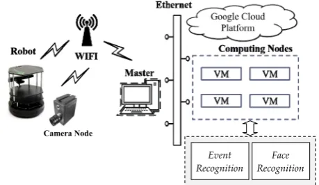
[image:2.595.57.287.597.730.2]Our major goal is to develop a video-based surveillance system for event and face recognition. As the analysis of video streams requires a large amount of computational effort, we integrate the surveillance system with a cloud computing platform to exploit the computational resources on the cloud. Figure 1 illustrates the system architecture and the core units of the system. As presented in the figure, our system includes two major parts for performing event and face recognition, respectively. The video data can be collected from the stationary camera nodes or the vision system mounted on the mobile robots. With the wireless connection, the collected video streams are sent to a master computer (PC) and then dispatched to the cloud. For the event recognition part, the raw image data are captured from the video sensor, and the pre-defined features are extracted from the marked regions. Then the features are reduced and feature data from different persons in the same region are combined to be a single data vector. Finally, classifiers are built from the training data and used for event detection and recognition. Similarly, for the face recognition part, a specific feature extraction procedure is performed and a machine learning approach is used (with some positive and negative image examples) to train a classifier for recognition. At present, only the face detection process is implemented; the face matching procedure has not yet included. The details are described in the sections below. As indicated above, our system includes mobile camera nodes (on the robots). Considering the compatibility of various software services provided by different parties, we configure a ROS (robot operating system, an open source robot middleware [8]) framework to convey the services between the requesters and the cloud host. Here, the cloud means the google cloud platform that can be rented conveniently with different system configurations on request. ROS focuses on providing a communication infrastructure and services for processes (and programs) based on a host operating system. It provides libraries and tools to support different programming languages, and this is helpful for software developers in creating robot applications. This operating system re-uses code from numerous other open-source projects. It exposes various configuration options and routes data into (out of) the respective software.
Fig. 1. The core units of our recognition system.
B. Feature Extraction and Event Detection
In the presented surveillance system, the part of event recognition is revised from our previous study using a smart
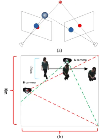
camera network for abnormal event recognition [4]. This section briefly describes the revised version working on the cloud. The first phase in event recognition is to extract specific target features from the video stream and then the system can infer what event is happening accordingly. Our system does not deal with all image frames in real time, but instead sample some frames within a specific time interval. In this work, we adopt the OpenCV (an open source computer vision library) that supports pedestrian detection by analyzing Histogram of Oriented Gradients (HOG). The HOG descriptor has several advantages: it captures local shape characteristics (i.e., edge or gradient structure) and upholds invariance to geometric and photometric transformations [9]. The system marks a region of interest (ROI) for each person detected (as shown in Figure 2 (a)), and we take the height of ROI as the feature data to represent a person. With the limited cost, it is essential to select a proper feature to achieve a reasonable system performance in real time. Here, we develop an approach to use the changes of ROI to constitute a feature vector. In the real world situations, the image frames included in a behavior sequence are not always reliable, due to the unexpected environmental effects (such as the clutter and occlusion problems). In this work, we use OpenCV to acquire ROI and choose not to deal with these problems particularly at the image processing level. Instead, we develop a collective decision method at the strategic level to enhance the robustness of event detection. Once a person’s behavior sequence is identified, a feature vector for a single pedestrian can be built. Figure 2 (b) illustrates an example of a behavior sequence recorded by the camera within a specific time interval (i.e., ten time steps) and the corresponding feature vector. In this example, the feature value below each time step represents the height of ROI measured.
The system needs to observe the behaviors of a group of people in the same region and then infers what event is happening. Here, an indirect encoding scheme is developed to derive a concise and compact representation from the feature vectors described above to represent the behavior sequences of a set of people. In this representation, the vector for each person is reduced to include three new features (i.e.,
f1, f2, and f3): the maximal change of the ROI height, the
number of image frames within which the maximal change happens, and the frequency of the considerable ROI change. The first feature f1 is to measure the maximal behavior
variation (i.e., the difference of the maximal and minimal ROI heights; the value could be positive or negative) of a person within a pre-defined time interval (i.e., ten time steps in our experiment). This value is normalized, subject to the maximal height. The second feature f2 means to describe the
changing rate from the maximal to minimal (or from minimal to maximal) heights in terms of the number of image frames. The third feature f3 indicates how often a person changes his
behaviors, and this is obtained by measuring the variation between two consecutive ROI heights (i.e., the slope value changes from positive to negative or from negative to positive) and checking if the variation exceeds a pre-defined threshold (20% of the first ROI height, determined by a preliminary test). For example, the behavior sequence shown in Figure 2 (b) is represented as <0.67, 9, 0>, in which 0.67 is the normalized change rate (from 170 to 56), 9 is the number Camera Node
Event Recognition
of frames corresponding to the interval of the above change, and 0 means no slope change in this interval.. In this way, the dimension of the combined feature vector can be largely reduced and the system performance can thus be improved. Here, each data vector means a group of ten people and includes thirty features in total, and it can be represented as <f11, f21, f31, f12, f22, f32, …, f1 10, f210, f310>, in which the
[image:3.595.305.550.51.180.2]superscripts are the identifiers of the people detected.
Fig. 2. (a) Extracting ROI from the original image; and (b) an example of the feature vector corresponds to a behavior sequence.
After encoding the behavior sequences of a group of people as feature data, we employ a machine learning method (i.e., SVM classifiers, due to its good performance in dealing with multi-class and high-dimensional data) to classify the target events occurring in a surveillance area. In this work, the classifiers are used for both single event recognition (with two classes of target and non-target events) and multiple event recognition (with four classes of events: earthquake, gun shooting, fighting, and normal). For the multi-event recognition, the output of the classifier needs to indicate which event is happening.
[image:3.595.54.287.163.380.2]To train a SVM classifier, the system includes the offline training and online operating phases, as illustrated in Figure 3. The training phase involves collecting historical video files and analyzing of video streams for features data extraction. The data are sent to a cloud computing platform to speed up the processing time. In this work, we use the online available software LISVM and chose the SVM type C-SVC (regularized support vector classification) with a kernel type of linear to construct the SVM classifiers. This configuration is selected as it achieves a good balance of the processing speed and the recognition accuracy. Once the classifier is constructed, it is then used for event recognition and detection in an online manner. The recognition phase operates on each single camera node. When a camera is monitoring the environment, it adopts sliding window in the way of “first in first out” to process the video frames. It accumulates a certain number of time-series data, and then inputs the feature data to the classifier to perform real-time event recognition.
Fig. 3. The flow of building a classifier for event detection.
C. Cloud-Based Multi-Camera Collaboration
As mentioned, a camera node has limited computational power and storage (compared to the traditional personal computer). Therefore it only functions for feature extraction and encoding. In many cases a single view is not sufficient enough to cover a targeted region, and a network of cameras is thus required to cope with an open area in which many people move arbitrarily. Individual cameras are often not able to capture complete behavior sequences perfectly, due to some environmental factors in the real world, such as the blind angles of the camera network, the light reflection and the obstruction between objects (e.g., Figure 4 (a)). Figure 4 (b) shows an example of gathering a complete behavior sequence by two cameras, in which each of the camera only captures part of the behavior. Therefore, each camera transmits the HOG data it has identified to the cloud to ensure the completeness of each feature vector (i.e., to mend any incomplete data) to achieve a correct recognition.
(a)
(b)
Fig. 4. (a) The case of obstruction happens between objects; (b) an example of behavior changes within two areas of coverage.
[image:3.595.327.493.437.669.2]processed information (i.e., the HOG data) for mending incomplete data. The cloud can mend an incomplete behavior sequence by comparing the features of the HOG data the cameras collected to perform person-matching, and then combining the features of the matched persons [10][11]. Figure 5 illustrates the example shown in Figure 4 (b). The upper part of Figure 5 is the pedestrian data collected from two cameras, and the lower part, the merged features. The data transmission interval can be determined in advance, depending on the system planning. In this way, the transmission load of the system can be largely reduced and the system can thus be scaled up to include more sensor nodes to monitor a huge surveillance area.
Fig. 5. A simulated example of the pedestrian data collected from two cameras (up), and the merged features (down).
D. System Adaption
[image:4.595.311.546.244.380.2]Because our goal is to detect abnormal event from the human behavior sequence, it is thus important to keep monitoring a complete space (to avoid the case shown in Figure 4). To achieve this goal, when a camera is damaged, the surveillance system needs to adjust (rotate) other cameras (for example, the neighboring nodes) to bridge the gap left to continuously monitor the original area. Here, we consider the surveillance case of a channel region, in which an alternate camera arrangement is deployed (as shown in Figure 6). This arrangement is popular as it can achieve a maximal monitoring coverage by a minimal number of cameras [12].
Fig. 6. The camera arrangement for a zone.
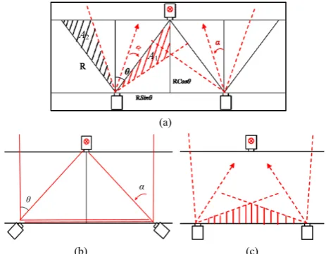
Figure 7(a) illustrates the general case with a damaged camera (the middle one), in which the two (left and right) cameras next to it need to be rotated to cover the vision gap. In this application case, the rotating angle can be calculated as the following. If the sensing angle of a camera is 2θ and the sensing radius is R, we can obtain the rotating angle α by maximizing the discrepancy (regarding as the gain) between the area of the bridged gap (A1 in Figure 7(a)) and the area that becomes invisible after a neighboring camera is rotated (A2in Figure 7(a)). From Figure 7(a), we can calculate A1 and A2 as:
(1) ) ( R 2 1 R 2 1 )) ( 90 ( R 2 1 R 2 1 2 2 2 2 1 cot sin cos sin tan sin cos sin A (2) ) ( R 2 1 R 2
1 2 2
2 sincos costan
A
The difference between two areas can be measured as:
(3) )] ( ) tan( [cos R 2 1 ) ( R 2 1 ) ( R 2 1 )] ( R 2 1 R 2 1 [ )] ( R 2 1 R 2 1 [ ) ( 2 2 2 2 2 2 2 2 1 cot sin tan cos cot sin tan cos cos sin cot sin cos sin f A A
Then, we can assign f’ to be zero to derive the maximum of α as the following:
0 )] ( ) ( [ R 2 1 )] ( ) 1 ( ) 1 )( ( [ R 2 1 ) ( 2 2 2 2 2 2 sec cos csc sin csc sin sec cos f That is,
R [ ( ) ( )] 0 (4)
2
1 2sincsc2 cossec2
1) -(4 ) ( ) ( 2
2
csc cos sec sin 2) -(4 ) ( ) ( 2
2
csc sec
tan (5) 2 0 ), 2 ( 0 , ) ( ) ( 2
2
cos sin
tan
From equation (5), we can observe that if θ = α = π/4, the gap area can be fully covered (Figure 7(b)); otherwise if θ <
π/4, there is still a gap (Figure 7(c)). Also, if both cameras rotate (π/2-θ) (or more) the gain turns to be negative. Based on the above analyses, the system can consider the application situation (such as the importance of different surveillance areas) to decide how to rotate the corresponding cameras,
(a)
[image:4.595.309.541.499.680.2]
(b) (c) Fig. 7. Collaborative adaption by camera rotation
E. Face Detection
In this work, the task of face detection is achieved by a machine learning approach in which a set of positive images (images of faces) and negative images (images without faces) are used to train a classifier and then features are extracted. The simple features used are reminiscent of Haar basis functions, which have been widely used in image recognition
A1
A2
[image:4.595.62.278.562.649.2][13]. Each feature is a single value obtained by subtracting the sum of pixels under white rectangle from the sum of pixels under black rectangle. In this method, all possible sizes and locations of each kernel are used to calculate plenty of features. Adaboost is then adopted to perform best feature selection. The details of this popular and efficient face detection approach are referred to the original work [13].
[image:5.595.55.285.421.580.2]Our system adopts OpenCV to achieve the above goal, in which a variant of AdaBoost is used to select a small set of features and to train the classifier. This weak (simple) learning algorithm is designed to select the single rectangle feature which best separates the positive and negative examples. For each feature, the weak learner determines the optimal threshold classification function, such that the minimum number of examples is misclassified. As mentioned in Section III.A, to perform the above calculation on the cloud, we configure a ROS cloud framework in which different types of computing nodes are pre-defined to handle the specified tasks. Figure 8 illustrates the operational flow for face recognition. The sensing node captures the face images and sends (called “published” in ROS) the data to the topic (the data transmission way defined in ROS) registered to the master node and other computing nodes can get (called “subscribe”) data from the topic. To achieve the distributed computing in the cloud platform, we insert a tag on each data header for identification purpose and the data are dispatched to specific computing nodes on the cloud accordingly. In this way, the time for face detection can be largely reduced and the faces can be detected in real time.
Fig. 8. The operational flow of the presented face recognition.
III. EXPERIMENTS AND RESULTS
A. Implementation
To develop a cloud-based video surveillance system, we configured a ROS framework on top of Linux OS to connect the sensing camera nodes. As indicted above, ROS focuses on providing a communication infrastructure and services for processes (programs) based on a host operating system. Often, a system built with ROS consists of a number of processes on a number of different hosts, which are connected at runtime in a peer-to-peer topology. Our current focus is on the development of using shared cloud resources; therefore, a simplified network architecture was used. In this environment, the ROS master was a PC running roscore and serving as the resource center for all the other ROS nodes connected to the network. The current ROS configuration
may result in traffic flowing across the wireless link, while it can be extended with a more efficient connectivity to avoid this issue for a large number of nodes.
B. Results of Recognition
A series of experiments has been conducted to evaluate the proposed approach for event recognition. The target events include earthquake, gun shooting, and fighting. For practical reason, a simulation-based strategy was adopted for data collection. In the experiments, the SVM classifiers were built for single event recognition, in which a 10-fold cross validation method was used to train and test the classifiers. After that, we employed the same approach to train classifiers for multiple events recognition. In the experiments involved multiple events, the output of the classifier needed to indicate which event (among the four) was happening. As mentioned, this work was extended from our previous study. Therefore, those sets of experiments conducted to verify the feasibility and reliability of our approach in event recognition (for single event and multiple events recognition) are thus not reported here (details are referred to [4]).
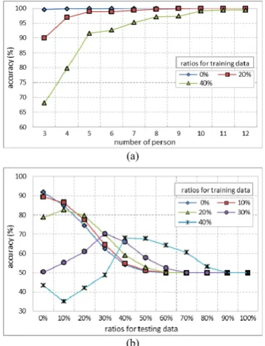
To investigate the effect of considering different numbers of people in the group for event recognition, we adopted the encoding scheme described previously and conducted a set of experiments to evaluate the corresponding performance of including different numbers of persons in each data record. The numbers ranged from three to twelve, and for each number three different ratios of impurity (0.0, 0.2 and 0.4) were arranged. Figure 9 (a) illustrates the results. As shown in this figure, though taking into account more persons’ behaviors (i.e., ten to twelve in our experiments) for event recognition can give better performance, it required higher computational cost. Accounting for both recognition accuracy and computational cost, ten people for each data record is a suitable choice for our work here.
(a)
(b)
Fig. 9. Results of (a) considering different numbers of persons for event recognition; (b) using the averaged feature values to substitute the missing values.
Monitoring Node Sensing
Node
topic: face recognition topic: sensing
data subscribe Computing Node
subscribe publish publish
[image:5.595.332.521.495.741.2]In a surveillances task, the number of people within the region monitored by a camera may be more or less than the expected number in practice. The system needs an efficient strategy to re-organize the data records to obtain best performance. For the case of more than the expected number of persons being identified, the system can simply choose the amount it needs based on a first-detected-first-chosen strategy. However, for the case without enough number of persons is not sufficient, the system needs to supplement some features to make a complete data record for training. A simple strategy was used in this set of experiments: taking a value averaged from the available features in each empty feature in the record. In the experiments, different ratios (percentages) of missing frames were tested. Figure 9 (b) present the recognition results, in which the x-axis indicates the ratio of missing persons in test data, and y-axis, the recognition performance. It shows that for the training cases with less missing data (e.g., 0~20%), the performance declined in a more natural way. In contrast, for the cases with relatively more missing data in training, the classifiers were less accurate in general. In both situations, the classifiers performed better when the ratios of missing data in the training and testing phases came close.
C. Performance of Cloud Computing
To evaluate the performance of using cloud computing resources for event recognition and face detection, we conducted a set of experimental trials with different numbers of computing nodes (ranging from one to five nodes). The computing nodes (rented from the google cloud platform) have the specifications of 2.6GHz Intel Xeon E5 CPU and 3.75 GB memory.
Figures 10 (a) and (b) present the response time (starting from the image frames taken by the cameras to the recognition results sent back by the cloud) for achieving event recognition and face detection, respectively. As shown in the figure, in both cases when the number of computing nodes increases (from one to five), the response time can be largely reduced (from 3850 ms to 681 ms for event recognition, and from 1210 ms to 642 ms for face detection). We have also noticed that the network connection caused some delay; otherwise the computing performance can be further improved. The results presented in Figure 10 confirm the efficiency of the proposed distributed approach.
IV. CONCLUSIONS AND FUTURE WORK
It is popular to employ video surveillance systems to monitor of public areas. More and more surveillance devices are now required to increase sensing coverage and to capture images from different visual angels. To reduce the large amount of computational resources often required in the video-based applications, in this study we presented a cloud computing framework to enhance the corresponding processing performance. Strategies have been developed to exploit the distributed computing provided by the cloud platform for the two major issues, event recognition and face detection, in a video surveillance system. In addition, we developed an adaptive mechanism to automatically adjust the visual angles of some neighborhood cameras to monitor the area when the faulty cameras cannot function properly.
Different sets of experiments have been conducted to evaluate the proposed approach, and the results show that our system has the quality of stability. We are currently investigating new ways to distribute the computational tasks and how to reduce the delay caused by the network connection to furthermore improve the performance.
0 1000 2000 3000 4000 5000
1 2 3 4 5
ti
m
e
(m
s)
num of nodes
(a)
0 200 400 600 800 1000 1200 1400
1 2 3 4 5
tim
e
(ms
)
num of nodes
[image:6.595.328.524.135.368.2](b)
Fig. 10. Response time of cases with different number of nodes for (a) event recognition; (b) face detection.
REFERENCES
[1] N. C. Krishnan and D. J. Cook, “Activity recognition on streaming sensor data,” Pervasive and Mobile Computing, vol. 10, pp. 138-154, 2014.
[2] A. T. Kamal, C. Ding, A. A. Morye, J. A. Farrell, and A. K. Roy-Chowdhury, “An overview of distributed tracking and control in camera networks,” in V. K. Asari (Ed.), Wide Area Surveillance: Augmented Vision and Reality, pp. 207-234, Springer, 2014. [3] T.-K. Truong, C.-C. Lin, and S.-H. Chen, “Segmentation of specific
speech signals from multi-dialog environment using SVM and wavelet,” Pattern Recognition Letters, vol. 28, pp. 1307-1313, 2007. [4] J.-Y. Huang and W.-P. Lee, “A smart camera network with SVM
classifiers for crowd event recognition,” in Proceedings on World Congress on Engineering, Vol. I, pp. 13-18, 2014.
[5] J.-F. Connolly, E. Granger, R. Sabourin, “An adaptive classification system for video-based face recognition,” Information Sciences, vol. 192, pp. 50-70, 2012.
[6] R. Jafri and H. R. Arabnia, “A survey of face recognition techniques,” Journal of Information Processing Systems, Vol.5, no.2, 2009. [7] C. Zhang and Z. Zhang, “A Survey of Recent Advances in Face
Detection,” Microsoft Technical Report MSR-TR-2010-66, 2010. [8] M. Quigley, K. Conley, B. Gerkey, et al., “ROS: An open-source robot
operating system,” in Proceedings of International Conference on Robotics and Automation, Workshop on Open-Source Robotics, 2009. [9] N. Dalal and B. Triggs, “Histograms of oriented gradients for human
detection,” in Proceedings of IEEE International Conference on Computer Vision and Pattern Recognition, pp. 886-893, 2005. [10] S. Fleck, F. Busch, and W. Straßer, “Adaptive probabilistic tracking
embedded in smart cameras for distributed surveillance in a 3D model,” EURASIP Journal on Embedded Systems, vol.1, 29858, 2007. [11] C.-H. Kuo, C. Huang, and R. Nevatia, “Inter-camera association of
multi-target tracks by on-line learned appearance affinity models,” in Proceedings of European Conference on Computer Vision, pp. 381-396, 2010.
[12] V. P. Munishwar and N. B. Abu-Ghazaleh, “Scalable target coverage in smart camera networks,” in Proceedings of ACM/IEEE International Conference on Distributed Smart Cameras, pp. 206-213, 2010. [13] P. Viola and M. Jones, “Rapid object detection using a boosted cascade