Setting and Checking the Performance of Multiplev
Distance Relays at Single Line to Ground Fault
Abdul Ghani A. A,
PhDDepartment of Electrical Engineering & Collage of Engineering Mosul University, Mosul, Iraq
ABSTRACT
Distance relays perform a major role in the protection of transmission lines. Distance relays are operated with different zones in order to demonstrate that they can provide better protection. This paper explains the modelling of distance relay using Matlab/Simulink package. The paper discusses in detail the response of multiple distance relays at single line to ground (SLG) fault. The setting of distance relays on IEEE 3 Bus is presented for a quadrilateral characteristic of distance relay, considering sensitivity and selectivity criteria for protection zones.
Keywords
Distance relay, IEEE 3Bus, Single line to ground (SLG) fault, Principals of distance relay, Setting of distance protection
1.
INTRODUCTION
Power transmission lines are vital to power systems as they constitute the power systems' backbone. Due to their spreading over long distances and their exposure to outdoor environment, the fault rate of the power transmission lines is much higher than that of the other parts of the power system [1]. Distance relays have been successfully used for many years as the most common type of protection of transmission lines. The development of electromechanical and solid state relays can be considered as an important factor in the wide spread acceptance of this type of protection at different voltage levels all over the world[2]. In the transmission line protection, the use of distance relays has found to be the most feasible and effective as compared to the other type of protection such as over current relay[3]. Distance protection, in its basic form, is a non-unit system of protection offering considerable economic and technical advantages, it is simple
to apply and it can be fast in operation for faults located along most of a protected circuit. It can also provide both primary and remote back-up functions in a single scheme[4]. A distance relay operates by measuring the electrical circuit distance between the relay location and the point of fault (apparent impedance) to determine if a fault is in its protection zone. It is apparent that the protection zones need to be set accurately to avoid overreaching or under reaching, and ensure the reliability and selectivity. Normally the protection zones can be set without considering the source impedance [5]. There are some parameters in transmission line like line resistance, source impedance, types of faults, fault location etc. which affects the impedance measured by distance relay. This leads to under reach or over reach of distance relay[3].
2.
DISTANCE PROTECTION SCHEME
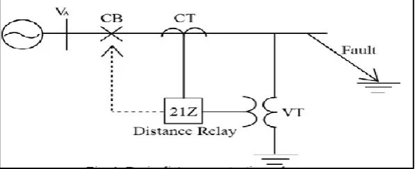
[image:1.595.149.448.537.659.2]Distance Relay has widely used a protective relay in a long transmission line nowadays. The Distance Relay achieves selectivity on the basis of impedance. As the impedance is proportional to the distance between the fault point and relay so the relay is directly indicated a distance of fault location. Distance relay is always set for instantaneous operation in the first zone, delayed operation in the second zone and provide back protection in the third zone [6].Fig. 1 shows the basic distance protection scheme of a transmission line. The impedance measurement inputs are the values of current and voltage phasors taken from the current transformer (CT) and voltage transformer (VT) respectively. The relays compare the setting impedance with the measured impedance to determine if the fault is inside or outside the protected zone. They immediately release a trip signal when the impedance value is inside the protective zone of distance relay [7].
Fig 1: Basic distance protection scheme.
3.
ZONES OF DISTANCE
PROTECTION
The principle of operation of the distance relay is based on measuring the impedance, at the fundamental frequency, between the relay location and the fault point. This gives the ability to determine if the fault is inside or outside the protected zone. Voltage and current values, measured by the
38 of the feeder (within 85% of the feeder protected length), the
protection circuit breakers are ordered to open instantaneously and without any delay. For faults outside this zone (faults at distances greater than 85% of the feeder protected length) and for faults within the adjoining circuits, the protection circuit breakers are ordered to open after some delays[1].
Zone 1 of distance relays is used to provide primary high speed protection, to a significant portion of the transmission line. Zone 2 is used to cover the rest of the protected line and
provide some backup for the remote end bus. Zone 3 is the backup protection for all the lines connected to the remote end bus. The implementation of distance relays requires understanding of its operating principles, as well as the factors that affect the performance of the device under different abnormal conditions [2].
Typical reach and time settings for a 3-Zone distance protection are shown below[5]:
Fig 2: Typical reach and time settings for a 3- zone distance protection.
From fig shown above:
Zone 1: this is set to protect between 85% of the line length AB and operates without any time delay[7]. This “under-reach” setting has been purposely chosen to avoid “over-reaching” into the next line section to ensure selectivity since errors and transients can be present in the voltage and current transformers. Also manufacturing tolerances limit the measurement accuracy of the relays[8,9]. Electromechanical/static relays usually have a reach setting of up to 80% of the protected line impedance for instantaneous Zone 1 protection. For digital/numerical distance relays, settings of up to 85% may be safe. The resulting 15-20% safety margin ensures that there is no risk of the Zone 1 protection over-reaching the protected line due to errors in the current and voltage transformers, inaccuracies in line impedance data provided for setting purposes and errors of relay setting and measurement. Otherwise, there would be a loss of discrimination with fast operating protection on the following line section. Zone 2 of the distance protection must cover the remaining 15-20% of the line[5].
Zone 2: this is set to protect 100% of the line length AB, plus at least 20% of the shortest adjacent line BC and operates with time delay t2. (0.2-0.5s) It not only covers the remaining %20-50% of the line, but also provides backup for the next line section.
Zone 3: this is set to protect 100% of the two lines AB, BC, plus about 25% of the third line CD and operates with time delay t3. (0.5-1.5s) [8,9].
[image:2.595.171.425.543.678.2]Careful selection of the reach settings and tripping times for the various zones of measurement enables correct coordination between distance relays on a power system [5]. The shape of the operation zones has developed throughout the years. An overview of relay characteristics can be seen in the Fig.3.Modern distance relays offer quadrilateral characteristic, whose resistive and reactive reach can be set independently which is shown in Fig 3.[10]
4.
MODELING IEEE 3 BUS SYSTEM & DISTANCE RELAY & RESULTS
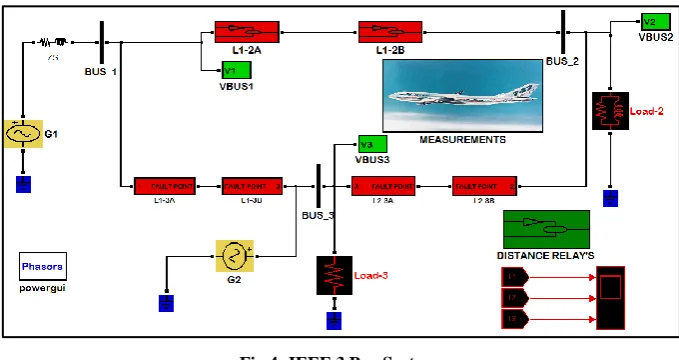
[image:3.595.127.467.100.280.2]The tested system was represented using the matlab as shown in Figure 4:
Fig 4: IEEE 3 Bus System.
[image:3.595.79.505.420.613.2]Three quadrilateral distance relays sensitive forward faults direction are designed for lines 1-2, 1-3 and 2-3, as shown in fig 5.
Fig 5: Three Quadrilateral Distance Relay Blocks for IEEE 3 bus.
Each relay as shown in figure (6), composite from:
1- measurement circuit to determine the measured impedance and then, measured resistance and measured reactance,
2- comparator circuit to compare measured (resistance and reactance) with setting (resistance and reactance)and
3- decision circuit to determine the trip zone and give the disconnecting order to C.B. at state of fault.
Fig 6: Stages of Quadrilateral Distance Relay.
[image:3.595.74.526.672.765.2]Table1 and table 2 show the setting for all designed distance relays in IEEE 3 Bus System.
Table.1: Setting resistances for all distance relays.
Distance relay Rset for zone 1 Rset for zone 2 Rset for zone 3 Time delay
Line 1-2 Rset 0.016 0.016 Rset 0.026125 0.026125 Rset
0.0425
instantaneous
Line 1-3 Rset 0.08 0.08 Rset 0.016125 0.016125 Rset
0.0325
0.2 sec
40 Table.2: Setting reactances for all distance relays.
Distance relay Xset for zone 1 Xset for zone 2 Rset for zone 3 Time delay
Line 1-2 Xset 0.032 0.032 Xset 0.0525 0.0525 Xset 0.08 Instantaneous
Line 1-3 Xset 0.024 0.024 Xset 0.0425 0.0425 Xset 0.075 0.2 sec
Line 2-3 Xset 0.02 0.02 Xset 0.04 0.04 Xset 0.075 0.5 sec
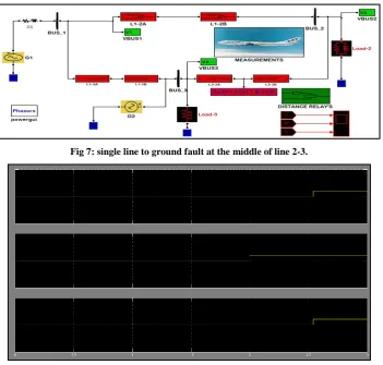
It is assumed that a single line to ground is happen at the middle of line 2-3 as shown in figure (7), distance relay for line 2-3 sensitive the fault at zone1 while each of distance
relay for line 1-3 and line 2-3 respectively sensitive the fault at zone 3, as shown in figure (8).
Fig 7: single line to ground fault at the middle of line 2-3.
Fig 8: trip signals for distance relays for IEEE 3 Bus system.
From fig (8) it is clear that the trip signal in the middle is instantaneous which related to the relay for line 2-3 because the fault is at zone 1,while the rest signals are delayed by 0.5
seconds which related to the relays for the rest lines because the fault at zone 3 for each distance relay at the rest lines.
5.
CONCLUSIONS
The setting and checking the performance of multiple distance relays for single line to ground fault are discussed in this paper. The distance relays are able to detect the fault in the different system conditions. The results shows a very good performance in the different fault condition, the setting of
distance relays is successfully from side of selectivity, sensitivity, reliability and quick response. A Matlab based distance relay was successfully developed and presented. For future enhancement, the model can be extended for other types of distance relay characteristic and fault type.
6.
REFERENCES
[1] A.S. Khraiwish, M. Alshamasin, R. Kassasbeh, Y. Al shiboul, Z. Al-Qudah and M. Al-Busoul,2009. “The Effect of the Harmonics, the Fault Location and the Fault Resistance on the Performance of the Impedance-Type Distance Relay”. American Journal of Applied Sciences 6 (4): 788-796, ISSN 1546-9239.
[image:4.595.124.476.237.572.2][3] T. M. Yesansure and T. G. Arora, 2013.” Numerical Quadrilateral Distance relay” .International Journal of Innovative Research in Science, Engineering and Technology, Vol. 2, Issue 7.
[4] A.R. van C. Warrington. Chapman and Hall,1962.”Protective Relays – their Theory and Practice”.
[5] Jayachandra S1 and Sivakumar G2 December 2014. “Calculation of Apparent Impedance and Distance Relay Tripping Characteristics in Ehv/Uhv Transmission Line with and Without Capacitance”. International Journal of Emerging Technology and Advanced Engineering Website: www.ijetae.com (ISSN 2250-2459, ISO 9001:2008 Certified Journal, Volume 4, Issue 12).
[6] Naitik Trivedi, Vivek Pandya1 and Vatsal Shah, 2016.”Distance Relay Characteristics Suitable For Dynamic Loading”.Journal of energy and management, Vol.1.
[7] Muhd Hafizi Idrisa,, Surya Hardia and Mohd Zamri Hasana, 2012. “Teaching Distance Relay Using Matlab/Simulink Graphical User Interface”. Malaysian Technical Universities Conference on Engineering & Technology, MUCET .
[8] TA Kahraman Yumak, 2013 .“Distance Protection”. ELK412 - Distribution of Electrical Energy Lab. Notes v1.0 web.itu.edu.tr/yumakk.
[9] Radhwan Mohammed Saleem, 2015.“Recommended Protection Scheme Setting Coordination For Nine Busbars Transmission Grid”. M.SC. Thesis. Faculty of Electrical and Electronic Engineering ,University Tun Hussein Onn Malaysia.