In resent years, there are many researches focused on investigating ultrasonic-imposed metal forming processes, such as ultrasonic-imposed drawing, ultrasonic-imposed bending, and ultrasonic-imposed deep drawing [1-3]. Through these researches, many effects caused by ultrasonic-imposed forming processes have been verified. For examples, reduction of friction factor, increase of material temperature, reduction of flow stress, reduction of springback, and better surface qualities. Pohlman is the first person who studies the effect of ultrasonic vibration in friction [4]. He used a device similar to a record player needle to test the
Abstract
The ultrasonic-imposed metal forming processes apply ultrasonic energy on the punch die, and then use the punch die to deform the workpiece. These processes decrease the interface friction and flow stress, and are able to achieve forming limits that traditional forming processes can’t do.
In this study, the focuses were the experiment design and finite element analysis for ultrasonic-imposed double-cup-extrusion test (DCET) to investigate material property, material flow, and mechanism of interface friction under DCET which is considered to be a new protocol for friction evaluation. In the research, the experiment design was conducted together with the construct of an apparatus for ultrasonic-imposed metal forming processes. The friction factor calibration curve was first obtained through the finite element software “DEFORM” in order to evaluate the interface friction factor of ultrasonic-imposed DCET processes.
The results show that in the DCET, the ratio of the height of the upper cup to the height of the lower cup is extremely sensitive to friction. With smaller diameter of the workpiece, the sensitivity of the cup height ratio gets higher. Further, under the effect of ultrasonic vibration, the forming force will be decreased, because the ultrasonic vibration increased the temperature of the workpiece. Meanwhile, the friction factor was also increased. With the lubrication of Blue Moly, the observed friction factors of the traditional and ultrasonic-imposed metal forming processes were 0.03 and 0.1 respectively.
Keywords: Ultrasonic-imposed metal formation, Fine element analysis, double-cup-extrusion test
1.Introduction
Manuscript received April 18, 2009. a
Department of Mechanical Engineering, National Chin-Yi University of Technology, Taiwan, ROC.(email: [email protected])
b
Department of Mechanical Engineering, National Chiao Tung University, Taiwan, ROC. (email: [email protected])
effect of ultrasonic vibration in friction and found that when the vibration direction is paralleled to the friction direction and the velocity of the vibrating point is faster than the contact velocity, the reduction of friction factor becomes significant. Mitskevich [5] presented a theoretical model for using the ultrasonic vibration to decrease the friction factor. Mikhenlman [6] believed that the change of friction factor was due to the increased temperature of the material surface.
In the ultrasonic-imposed drawing-related researches [7-8], experiment results proved that the ultrasonic vibrating can effectively improve the friction surfaces conditions and decrease the drawing forces. Also, the decrease of surface friction was considered to be the main reason of the reduction of drawing forces. Therefore, some studies try to analyze the mechanism of drawing force reduction and improvement of lubrication under ultrasonic vibration. Murakawa and Jin [9] proposed a friction mechanism and verified it by applying axial and radial ultrasonic vibration on the die during drawing processes. During the analysis process, they neglected elastic response during drawing process. When the vibrating speed was larger than the moving speed of drawing die, either in axial or radial vibrating, the workpiece and the drawing die separated in every cycle. The gap between them decreased the whole friction force. The gap changed with the relative velocity between workpiece and drawing die. It also changed with the amplitude of vibration of the drawing die.
During ultrasonic-imposed forming process, the interface temperature increased, and then changed the material property of the interface. Rudkins [10] used the hot ring compression test to prove that when the material temperature increased, the friction factor of the interface also increased. Therefore, the effect of ultrasonic vibration on friction would depend on the characteristic of forming process.
Following the applications of 3C products and the demands from consumers, products will be developed toward lightness, thinness, shortness, smallness and delicacy. The metallic cases for 3C products have acquired growing popularity because of the advantages: unique and high quality feeling, high speed heat releasing, electromagnetic wave insulation, impact resistance and high strength. Most of the metallic cases used for 3C products belong to thin wall construction. Although sheet metal stamping process has advantages of better surface quality, faster production, high yield rate, and high strength, the forming of the boss and ribs in the cases is still difficult. Recently, a new manufacturing method called “press forging” [11] has been developed to overcome these difficulties. It combines stamping and forging techniques to form the shape of products by drawing, bending and pressing the sheet metal and the boss and the ribs are forged simultaneously. Although the press forging technique can forge the boss and ribs, the high forming force will decrease the lifespan of the dies. Because ultrasonic vibration has the
The Influence of Ultrasonic-Vibration on Double
Backward-Extrusion of Aluminum Alloy
advantage of decreasing the forming force, ultrasonic-imposed press forging will be a major technique for 3C products manufacturing.
The friction between dies and workpiece plays a very important role in metal forming process such as forging, extrusion and rolling. The friction conditions at the die-workpiece interface influence the force, the mode of deformation, the quality of the finished products and the resulting surface roughness. High friction force will induce heat, abrasion and graze on the surface of the die. Friction force will also increase anisotropic deformation, and thus brings defects to the workpiece. Lubricant can be used to decrease but not totally eliminate the friction force. Generally the friction factor must be evaluated and quantified in order to optimize the process to enhance the tribological conditions in metal forming.
Although it is easy and quick to evaluate friction factor by traditional ring compression test, the contact area, strain value and normal pressure in this test are relatively small. Therefore, the friction condition for forging process characterized by high pressure on the interface, severe material flow and large contact area cannot be realistically simulated by ring compression test. Buschhausen et al. [12] developed a new evaluative test method called “double-cup-extrusion test (DCET)”. They used the experiment results to verify the FEM results and discussed effects of cup height ratio (
l
u h
h / ) and area reduction ratio on the friction factor. Engel [13] fixed the height diameter ratio (
0 0/D
H ) of specimen and extrusion area ratio, then proceeded the DCET (shown in fig. 1) with different diameter of specimen to examine the size effect. Compared to ring compression test, DCET has large contact area, contact pressure and strain value. Therefore, DCET was adopted to evaluate the friction factor in ultrasonic-imposed press forging.
2. DCET
In DCET, a cylindrical workpiece was positioned between two punch dies. The punch dies had identical shapes, the lower one is fixed and the upper one is axially movable. During test, the upper punch die pushes down and deforms the workpiece into two cups of different heights. Theoretically, if there is no friction (m=0) on the interface, both cups will have the same height. The higher the friction (m>0), the shorter the lower cup will be. This is because that when the upper punch die moves down, the relative velocity between the lower punch die and lower parts will be smaller than that between the upper punch die and upper parts of the workpiece, and results in smaller deformation. The cup height ratio R is defined as:
R=Hu/Hl (1)
The measurements of Hu and Hl are shown in fig. 1. If the
friction factor is zero, R will be 1. On the contrary, R will increase with the increase of friction factor.
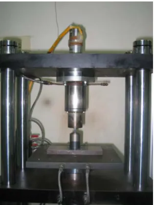
2.1 Experimental apparatus of DCET
In this study, an in-house made micro-computer aided hot pressing machine was constructed for the experiment. The maximum loading is 5000kgw with precision of 1/20000. The displacement resolution is 0.005mm. An ultrasonic source (KWS2020, King Ultrasonic Co.) with 20 kHz frequency and
2kW maximum power is coupled with a home-made amplifying horn to provide the needed ultrasonic vibration.
During the DCET, the ultrasonic vibration was applied on the upper punch die. The lengths of the punch dies were 20mm and different diameters (2mm, 3mm and 4mm) were tested as shown in fig. 2.
2.2 Experimental conditions and procedure
Table 1 presents the material of the workpiece and the DCET conditions. The diameter of the workpiece was 6mm and the height was also 6mm. The extrusion increments were 2mm, 3mm and 4mm (compression ratio: 33.3%, 50% and 66.7%). The extrusion velocity was fixed at 0.033mm/s. The diameters of the punch dies were 2mm, 3mm and 4mm (area reduction ratio of extrusion: 11.1%, 25% and 44.4%). The lubricant applied between the interface of punch die and workpiece is Blue Moly which can endure high pressure and temperature.
Experiment began by setting the ultrasonic vibration system and the DCET die above the plate of the micro computer controlled hot imposing machine. Then lubricant was applied on the workpiece before it was put into the extrusion sleeve and punch dies. A 20kgw preload was applied on the workpiece and, and the ultrasonic vibration was activated on the upper punch die and once loading force reached 70kgw.
In order to examine the flow stress behavior under ultrasonic vibration and to verify the simulation result, workpieces were cut into two semi-cylinders (fig. 4). After grid patterns were etched onto cutting surfaces, the workpieces were then reassembled to proceed with the DCET.
2.3 Experiment results
Fig. 5 shows the experiment results of the traditional and ultrasonic vibration extrusions corresponding to different punch die diameters. Under identical friction condition, in both tradition and ultrasonic-imposed DCET, as the punch die diameter becomes smaller, the cup height ratio becomes larger. That is when the area reduction ratio gets smaller, the cup height ratio gets larger. Fig. 6 shows the final specimen of tradition double cup extrusion.
Fig. 7 shows the comparisons of traditional and ultrasonic imposed DCET with different punch die diameters. As shown in the figure, under the effect of ultrasonic vibration, the cup height ratio had more tendency to increase than traditional DCET. The increasing tendency became much obvious with the increasing of friction factor (it means the ultrasonic vibration will increase the friction factor).
Fig. 8 shows the deformed grid patterns for the traditional DCET. Although the material flow can be seen from the grid of cross-section, the workpiece cross-section was bulged out due to the extrusion. The reason may be that after the two semi-cylinders were reassembled, the final diameter of workpiece became smaller and make it difficult to fit exactly with the sleeve.
3. The simulation of double cup extrusion 3.1 The finite element model
The finite element software DEFORM was used in this research and the features of “automatic mesh generation” and “automatic remesh” were activated in this study to overcome the negtive Jacobian problem when mesh was in serious deformation during the simulation of DCET.
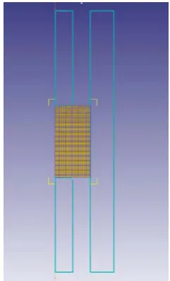
Two dimensional axisymmetric model was chosen to simplify this numerical simulation. Fig. 10 represents the FEM analysis model. Table 2 shows the simulation condition. During DCET simulation, the workpiece material was regarded as rigid plastic and the punch die as rigid body. The material properties which needed in the simulation were obtained from the true stress-strain relation through previous compression corrective test [14]. The friction condition of the interface between punch die and the workpiece was determined by friction factor (m). The compressive velocity is 0.033mm/s. The height reduction is 83.33%.
Fig. 11 shows the friction calibration curves for different punch die diameters. It shows that the simulation had the same tendency with experiment results, i.e. cup height ratio increased while the area reduction ratio deceased.
4. Results and discussion
During the DCET, the upper punch die moved downward, but the lower punch die and sleeve were fixed. Thus, the sleeve had a relative upward velocity with respect to the upper punch die. Therefore, the workpiece had more restrictions in the direction of moving downward. When interface friction occurs, the height of the upper cup will be larger than that of the lower cup, and the differences gets more obvious with the increasing of friction factor.
As shown in fig. 5 and fig. 11, experiment and simulation results show the same tendency. Cup height ratio increased when the area reduction ratio deceased. It was presumed that with the smaller diameter punch die, the extrusion force gets smaller and the workpieces deformation restriction gets smaller. So, under the same interface friction condition, the friction force yields much more effects which resulted in the increasing of upper cup height and the decreasing of lower cup height. Therefore, the smaller the punch die diameter, the higher the sensitivity to the interface friction factor. If smaller punch die was used, much sensitive friction calibration curve can be expected.
Fig. 12 is the comparison of punch die loading between traditional and ultrasonic imposed DCET. As shown in the figure, the traditional DCET loading is 14293.447N, ultrasonic imposed DCET loading is 11514.941N. It proved that under the activation of ultrasonic vibration, the extrusion force will be decreased. The reason of decreased force might be the increase of the material temperature caused by the ultrasonic vibration [6], which soften the workpiece material and decrease the forming stress of the material.
As shown in fig. 7, during DCET, ultrasonic vibration will increase the cup height ration and the increasing tendency becomes more obvious with the increase of friction factor. From fig. 8 and fig. 9, one can find that when ultrasonic vibration is acting, the materials deform much easier and melting phenomenon occurs around the top of cup. Therefore, we can presume that ultrasonic vibration will raise the temperature of workpiece, step up the fluidity of material and increase the cup height ratio.
The results verified that ultrasonic vibration increases the interface friction factor. From the traditional and ultrasonic imposed DCET and friction calibration curve, one can find that by using the same interface lubricant, the friction factor of traditional DCET is 0.03, and the friction factor of ultrasonic imposed DCET increase to 0.1. The reason can be presumed to be the rising temperature from ultrasonic vibration.
5. Conclusion
In this study, the design and experiment of ultrasonic imposed DCET were conducted, and the finite element analysis software DEFORM was used to complete the friction calibration curve. The results of this study can be summarized as follows:
1. It is very sensitive to evaluate interface friction factor with DCET. When area reduction ratio gets smaller, the sensitivity to the friction factor gets higher. 2. The results from experiment and simulation confirms that the loading force decreases under the effect of ultrasonic vibration.
3. In the Blue Moly lubricant condition, the traditional DCET friction factor is about 0.03, and the ultrasonic imposed DCET friction factor increases to 0.1.
4. The ultrasonic vibration rise the material temperature and thus increase the friction factor during DCET.
Acknowledgment
The present research was made possible through grants from the Nation Science Council (NSC- 96 -2628 –E -167 -015 -MY2), Taiwan.
Reference
[1] J. Tsujion, “Ultrasonic vibration bending of metal plate specimens”, Proc. IEEE 1989 Ultrasonic Symposium, 1990, pp.1099-1102.
[2] T. Jimma, “An application of ultrasonic vibration to the deep drawing process”, Journal of Materials Processing Technology, 1998, pp.406-412.
[3] M. Jin, “Utility of ultrasonic vibration applied to metal-forming processes”, Advanced Technology of Plasticity, 1999, pp.19-24.
[4] R. Pohlman, and B. Lehfeldt, “Influence of Ultrasonic Vibration on Metallic Friction”, Ultrasonics, 1966, pp. 178-185.
[5] A. M. Mitskevich, “Motion of a body over a tangentially vibrating surface”, Soviet Physic-Acoustic”, 1968, pp.348-351.
[6] A. I. Mikhenlman, A. N. Mashchinov, “Effect of ultrasonic vibrations on friction between solids”, Russian Engineering Journal, 1969, pp.42.
[7] V. P. Severdenko,V. Z. Zhilkin, “Wire drawing with ultrasound”, Russian Ultrasonics, 1974, v.4, n1, pp. 17-22.
[8] K. Siegert, “Wire drawing with ultrasonically oscillating dies”, Journal of Materials Processing Technology, 1996, pp.657-660.
[10] N. T. Rudkins, P. Hartly, I. Pillinger, D. Petty, “Friction modeling and experimental observations in hot ring compression tests”, Journal of Materials Processing Technology, 1996, v60, pp.349-353.
[11] Fuh-Kuo Chen , Tyng-Bin Huang and Shin-Gee Chen, ” Embossment formation in press forging of AZ31 magnesium-alloy sheets”, 272-279.
[12] A. Buschhausen, K. Weinmann, J. Y. Lee and T. Altan, ”Evaluation of lubrication and friction in cild forging using a double backward-extrusion process”, Journal of Materials Processing Technology, 1992, Vol. 33, pp. 95-108.
[13] U. Engel, R. Eckstein, “Microforming – from basic research to its realization”, Journal of Materials Processing Technology, 2002, Vol. 125-126, pp. 95-101. [14] Jung-Chung Hung, Yu-Chung Tsai, Chinghua Hung,
“Frictional Effect of Ultrasonic-vibration on Upsetting”, Ultrasonics
Figures
(SCI, EI), June 2007, Vol. 46, pp. 277-284
[image:4.595.350.508.49.259.2]Fig. 1. Double cup extrusion test【12】
Fig. 2. Ultrasonic punch die
[image:4.595.52.283.132.630.2]Fig. 3. The experimental apparatus of DCET
Fig. 4. Semi-cylinders of aluminum alloy
(a) Traditional DCET
(b) Ultrasonic imposed DCET
[image:4.595.314.541.398.750.2](a) Punch die diameter: 2mm
[image:5.595.367.488.49.248.2] [image:5.595.78.263.50.219.2](b) Punch die diameter: 3mm Fig. 6. Traditional DCET results
[image:5.595.60.283.268.419.2]Fig. 7. The comparison of traditional and ultrasonic imposed DCET
Fig. 8. The deformed grid patterns of traditional DCE experiment
[image:5.595.313.543.279.741.2]Fig. 9. The deformed grid patterns of ultrasonic imposed DCE experiment
Fig. 10. The FEM model of ultrasonic imposed DCET
(a) punch die diameter:2mm
(b) punch die diameter:3mm
(c) punch die diameter:4mm
[image:5.595.75.268.598.746.2]Fig. 12. Traditional and ultrasonic imposed DCET loading curve
(a) Traditional DCET
[image:6.595.55.287.224.544.2](b) Ultrasonic imposed DCET
[image:6.595.26.313.599.702.2]Fig. 13. Traditional and ultrasonic imposed DCET friction calibration curve, respectively
Table 1. Material and DCE experiment condition Specimen material Aluminum Alloy (A 6061)
Tooling material Stainless steel (SUS304) Size of specimen φ6.0
×
6.0mmLubricant Blue Moly
Reduction (R) 11.1%、25%、44.4%
Extrusion speed 0.03 1/s
Temperature of specimen 25C
Table 2. Finite element analysis condition
Ring workpiece I. PLASTIC DEFORMABLE
Die Rigid body
Simulation moded Axial symmetric model
Simulation software DEFORM 2D