Novel approach of crater detection by crater
candidate region selection and matrix-pattern-oriented
least squares support vector machine
Ding Meng
a,*
, Cao Yunfeng
b, Wu Qingxian
ba
College of Civil Aviation, Nanjing University of Aeronautics and Astronautics, Nanjing 210016, China
bCollege of Automation Engineering, Nanjing University of Aeronautics and Astronautics, Nanjing 210016, China
Received 21 May 2012; revised 18 July 2012; accepted 15 October 2012 Available online 7 March 2013
KEYWORDS
Crater candidate region; Crater detection algorithm; Kanade–Lucas–Tomasi detector;
Least squares support vector machine;
Matrixization
Abstract Impacted craters are commonly found on the surface of planets, satellites, asteroids and
other solar system bodies. In order to speed up the rate of constructing the database of craters, it is important to develop crater detection algorithms. This paper presents a novel approach to automat-ically detect craters on planetary surfaces. The approach contains two parts: crater candidate region selection and crater detection. In the first part, crater candidate region selection is achieved by Kanade–Lucas–Tomasi (KLT) detector. Matrix-pattern-oriented least squares support vector machine (MatLSSVM), as the matrixization version of least square support vector machine (SVM), inherits the advantages of least squares support vector machine (LSSVM), reduces storage space greatly and reserves spatial redundancies within each image matrix compared with general LSSVM. The second part of the approach employs MatLSSVM to design classifier for crater detec-tion. Experimental results on the dataset which comprises 160 preprocessed image patches from Google Mars demonstrate that the accuracy rate of crater detection can be up to 88%. In addition, the outstanding feature of the approach introduced in this paper is that it takes resized crater can-didate region as input pattern directly to finish crater detection. The results of the last experiment demonstrate that MatLSSVM-based classifier can detect crater regions effectively on the basis of KLT-based crater candidate region selection.
ª2013 Production and hosting by Elsevier Ltd. on behalf of CSAA & BUAA.
1. Introduction
Impact craters formed by collisions of meteoroids with plane-tary surface are commonly found on the surface of planets, sat-ellites, asteroids and other solar system bodies. The relative parameters including the quantity, distribution, pattern, mor-phology and dimension of craters obtained from images can establish the age of the surface or surface units of different bodies.1,2 Because of such importance of craters, various researchers are collecting datasets of craters and attempt to * Corresponding author. Tel.: +86 25 85368892.
E-mail address:[email protected](M. Ding).
Peer review under responsibility of Editorial Committe of CJA.
Production and hosting by Elsevier
Chinese Society of Aeronautics and Astronautics
& Beihang University
Chinese Journal of Aeronautics
[email protected]www.sciencedirect.com
1000-9361ª2013 Production and hosting by Elsevier Ltd. on behalf of CSAA & BUAA.
http://dx.doi.org/10.1016/j.cja.2013.02.016
Open access under CC BY-NC-ND license.
build the information database of craters,3such asThe Barlow Catalog of Large Martian Impact Craters, which is ongoing and contains information of 42283 craters of Martian surface.4 After the primordial manual counting, in order to speed up the rate of constructing the database of craters, several attempts to create reliable methods for autonomous crater detection have been developed.
Generally, the methods of crater detection can be catego-rized into three categories: unsupervised (fully autonomous), supervised (machine learn) and combinative method. Unsuper-vised methods apply the related theory of image process and object detection including approaches of Hough transform (HT) and improved algorithms,5,6template matching,7,8 genet-ic algorithm (GA)9and radial consistency10to detect craters. Unsupervised methods do not need any training process which should require a large number of labeled examples to learn an accurate classifier. These methods work well in the limited con-text of an autonomous spacecraft navigation system, but are not robust when applied to the images containing complex ter-rain. Supervised methods use machine learning conceptions and approaches of pattern recognition to construct classifiers for crater detection, such as neural network,11Support vector machine (SVM)12and Adaboost approach.13Supervised meth-ods have been applied widely in different fields of pattern rec-ognition and image analysis. Detection results of supervised methods can be improved by selecting different types of craters as positive samples and different negative samples according to the surrounding terrain. Ref. 12 showed that the supervised methods based on SVM or improved algorithms are signifi-cantly better than the other methods based on other intelligent algorithms. The purpose of combinative methods employing multiple approaches including unsupervised and supervised methods is to improve the rate of cater detection and offer im-age patch as the input of supervised methods.14In a word, as a classic problem of pattern recognition, all of these methods can be divided into four steps or processes: preprocess, feature extraction, classifier design and detection. According to four steps, the approach proposed in this paper combines super-vised with unsupersuper-vised methods to detect craters.
Generally, the vector representation is natural in most of feature extraction for pattern recognition including the afore-mentioned methods of crater detection. The aim of feature extraction is to transform the input pattern into the feature vector which represents each pattern sample as a point in n-dimensional feature space. However, there is no standard or perfect approach for the crater feature extraction in the cur-rent. Sometimes, we directly use gray values of all pixels as fea-ture.12 Obviously, when each image pattern is converted to vector, the spatial redundancies within each image matrix are not fully utilized, and some of the information about local spa-tial relationship is lost. For instance, a typical crater in the im-age has an elliptical rim and a bright to dark shading pattern and inside it the image intensity profile along lighting direction should be a monotonously decreasing function. When a pat-tern feature to be processed is an image including a single cra-ter, it first has to be transformed or vectorized into a vector pattern by concatenating its pixels in some way. In this in-stance, the information of intensity distribution of crater image will be lost.
Because of that, pattern classifier represented by the matrix which directly uses the image matrix is one of the possible directions of development of pattern recognition technology.
In fact, several researchers have made such attempts along this line. Hong employed singular value decomposition (SVD) to extract a set of singular values as classification features directly from the image matrix.15Liu directly used a set of given train-ing image matrices to construct an optimal discriminant crite-rion and subsequently employed this criterion for classification.16Yang et al. proposed two-dimensional princi-pal component analysis (2DPCA) that extracts features di-rectly from the two-dimensional images.17
Support vector machine is a concept in computer science for a set of related supervised learning methods that analyze data and recognize patterns used for classification and regression analysis. The goal of SVM aims to minimize the Vapnik–Chervonenkis (VC) dimension by finding the optimal hyperplane with the maximal margin. One of the major disad-vantages of SVM is finding this optimal hyperplane by solving a constrained optimization criterion using quadratic program-ming (QP) leads to higher computational cost.18 Compared with the conventional SVM, least squares support vector ma-chine (LSSVM), which can obtain an analytical solution di-rectly from solving a set of linear equations instead of QP through replacing inequality constraints with equality con-straints, can efficiently reduce the computational cost.19 How-ever, the new research proves that LSSVM loses the sparseness in its solution and leads to the fact that LSSVM has to store the training set for subsequent classification such that the memory overhead is greatly increased. Therefore, Chen et al. presented a method which directly manipulated original image (matrix) patterns by means of the matrix algebra and LSSVM, called matrix-pattern-oriented least squares support vector machine (MatLSSVM).20 This method cannot only inherit the aforementioned advantages of LSSVM, but also directly operate on matrix patterns and reduce memory for the weight vectors.
In this paper, inspired by the method of feature extraction directly based on matrix patterns and the advantages of LSSVM, MatLSSVM will be able to detect craters which have meaningful characteristics of bowl shaped depression and im-age intensity. As preprocess of crater detection, Section 2 pre-sents an algorithm for crater candidate region (CCR) selection. In Section 3, matrix-based least squares suppose vector ma-chine is introduced and a novel approach of craters detection by matrix patterns-based LSSVM is demonstrated. Experi-ment, discussion and conclusion are shown in Sections 4 and 5 respectively.
2. Kanade–Lucas–Tomasi-based crater candidate region selection
The considered CCR in this paper consists of several small rectangular regions of the image which would be detected. Every crater in the original image is contained in different CCRs. Therefore, most non-crater patches are quickly rejected by CCR selection which is illumed by cascade detector from face detection and demonstrates impressive detection speed. Because each CCR includes only one or no crater, we can re-size CCR by image geometric transformation according to the dimensionality request of trained classifier, and the resized CCR can be taken as a test sample for crater detection directly. The architecture of the approach presented in this pa-per is shown in Fig. 1. The Kanade–Lucas–Tomasi (KLT)
detector-based crater region selection is described in more de-tail in this section.
2.1. KLT feature points extraction
A typical crater in intensity images has a circular or elliptical rim and a bright to dark shading pattern and inside of it the image intensity profile along lighting direction should be a monotonously decreasing function. Therefore, intensity varia-tions of crater region are strong in images. In computer vision and image processing, feature points which have the strong variation in different directions are usually used for matching and tracking. Owing to importance of feature point extraction in different research fields, many algorithms for feature point extraction have been described in Ref. 21 KLT detector is one of methods which search for feature points directly from the grey-level images and extracts feature points by computing eigenvalues of the matrix composed of image pixels which rep-resent intensity variations in two vertical directions.22 Accord-ing to this principle, the KLT detector can be used for crater candidate selection. KLT detector-based algorithm for CCR selection is expressed simply as follows.
Step 1: Computing the image gradient across the image at each pixel location
Ixðx;yÞ ¼Iðxþ1;yÞ2Iðx1;yÞ
Iyðx;yÞ ¼Iðx;yþ1Þ2Iðx;y1Þ (
ð1Þ
where I(x,y) denotes the continuous function defining the brightness values of a sequence of images. The partial deriva-tives ofI(x,y) with respect tox,y, are denoted respectively by Ix(x,y) andIy(x,y).
Step 2: Defining matrixG
G¼ X W1 ðIxðx;yÞÞ 2 X W1 Ixðx;yÞIyðx;yÞ X W1 Ixðx;yÞIyðx;yÞ X W1 ðIyðx;yÞÞ 2 2 6 6 4 3 7 7 5¼ a b b c ð2Þ where W1 denotes feature patch of pixels including pixel point(x,y). Actually, feature point obtained by KLT algorithm is a patch including several pixels. In general,W1= 7·7 and determines the area of feature patch(point). Therefore, in this paper, the selection ofw1only denotes the area of the feature points and is not related to the size of craters.
Step 3: Computek1(x,y), k2(x,y), where k1<k2,k1is the minimum eigenvalue of every image pixel (x,y).
Step 4: Discard any pixel withk1(x,y) <kth, wherekthis a threshold. In KLT-based feature point extraction, the value of kthdetermines the number of extracted points. The value ofkth is inversely proportional to the number of feature points which is proportional to the number and dimension of craters in images for detection. In this paper, the value ofkthis selected by manual method according to the above relationship.
2.2. Crater candidate region selection
In order to detect all CCRs as far as possible, the exhaustive search strategy is used to compute every pixel. Due to the com-putational complexity of KLT detector, Ref.22offers the real-time implementation of this algorithm by removing the square root operation in the minimum eigenvalue computation of ma-trixG. Before extraction of feature points, 3·3 median filter is used for noise reduction and further causes too small craters (63·3) to be detected.
Fig. 2(a) demonstrates an original image including craters. The minimum eigenvalues according to every pixel ofFig. 2(a) are shown inFig. 2(b). WhenW1= 7·7 andkth= 200, ‘‘+’’ of Fig. 2(c) shows the result of KLT-based feature point extraction. InFig. 2(c), every feature point in fact represents a 7·7 window. Set the value of all pixels belonging to the win-dows representing feature points to 1 and the others to 0, a binary image is obtained and shown inFig. 2(d).
Because of the gray variance of the crater image caused by the terrain structure of the crater, feature points usually dis-tribute the center of the small crater and both sides of the edge and center of the big crater. Thus, we can use the number and distribution of points to determine the size of CCR. In
Fig. 2(d), there are 14 white regions representing the distribu-tion of feature points. The locadistribu-tion and size of every CCR can be determined by the minimum and maximum of the row and column coordinates of all pixels belonging to every white re-gion.Fig. 2(e) demonstrates the results of CCR selection.
3. MatLSSVM-based crater detection
FromFig. 2(d), we find that selected CCRs can be divided into two types, the first is the region containing a crater and the other is the region containing non-crater. Generally, because the terrain structure causes gray variance, the CCR of non-cra-ter is rugged and contains several rocks. The purpose of this part is to design classifier to detect the regions containing a crater from CCRs obtained by KLT-based method.
3.1. Matrix-pattern-oriented least squares support vector machine
LSSVM, the least squares version of SVM, uses the equality type constraints instead of inequality type constraints. Thus, the solution of LSSVM follows from solving a set of linear equations instead of QP of conventional SVM and the compu-tational cost of LSSVM is rather lower than that of SVM. MatLSSVM, for two-class problems operating directly on matrixized patterns, proposed by Wang, is the matrixized ver-sion of LSSVM.20MatLSSVM inherits the advantages of both the matrixization method and LSSVM, such as the capability
of small sample recognition from SVM, space structure reserve and low-dimensional feature from matrixization method.
Considering the two-class classification problem in the ma-trix case:
S¼ ðfAi;YiÞji¼1;2;. . .;lg Rd1d2 þf 1;1g ð3Þ
whereiis the number of samples, andd1·d2the space dimen-sionality of matrix pattern. The aim of MatLSSVM-based classification is to construct a classifier with the decision func-tion of the following form:
fðAiÞ ¼uTAivþb ð4Þ
whereAi2Rd1d2 is the matrix pattern of sample,u2Rd1 the
left weight vector, v2Rd2 the right weight vector, and b, a bias. For the training patterns in S, the following condition must be met to the greatest extent:
fðAiÞ ¼uTAivþb
Pþ1; if yi¼ þ1 1; if yi¼ 1
i¼1;2;. . .;l ð5Þ Furthermore, integrate their corresponding binary class labels:
yifðAiÞ ¼yiðu TA
ivþbÞ 1; i¼1;2;. . .;l ð6Þ
The following derivation process of the MatLSSVM is the same as that of LSSVM. In this paper, the details of Mat-LSSVM are summarized and given below:
Step 1: Givev0as the initial value of right weight vectorvt,
in whichtis the iterative counter.
Step 2: In accordance with the matrix pattern space S¼ fA1;A2. . .;Alg and right weight vector vt, compute the
vector pattern space:
St¼ fx1;x2. . .;xlg ¼ fA1vt;A2vt;. . .;Alvtg ð7Þ
Step 3: Getb;athrough the following equation
0 ½y1y2 yl ½y1y2 ylT XþEll=C b a ¼ 0 ll1 DQ ð8Þ
whereais the vector of lagrange multipliers,Ean identity ma-trix,Cis a regularization constant,X2Rll;Xij¼yiyjKðxi;xjÞ,
Kðxi;xjÞ is the kernel function and motivated by Mercer’s
theorem.
Step 4: Obtainut¼P l
i¼1aiyiAivt;
Step 5: Updatevtthrough the following equation:
vtþ1¼vtg Xl i¼1 aiyiA T iut ! ð9Þ wheregis the learning rate.
Step 6: If t is less than the set iterative count, make t=t+ 1, and then go to Step 2, else finish computation.
After finishing the process of training, we can obtain the right and left weight vectorsuandv, and the biasb. Further-more, the decision function of the classifier for input matrix patternZas test sample can be represented:
fðZÞ ¼uTZvþb >0 then Z2classþ1
<0 then Z2class1
ð10Þ In summary, MatLSSVM is comprised of two procedures: Getting the final solution tovby an iterative algorithm; gain-ing an analytical solution toucorresponding to each fixedv. As noted above, for the same pattern Ai2Rd1d2;the space
that MatLSSVM needs to store the weight vectorsuandvis d1+d2and the space that the vector in accordance with linear kernel needs to store the weight vector is d1·d2. Obviously, the ratio r of the spaces that the two different versions of SVM need is
r¼d1þd2
d1d2 ð11Þ
3.2. Crater classifier design
As one of the key technologies of aerospace science, although relevant contributions and achievements of crater detection have been presented over the years, the fitness and degree of generalization of those algorithms is not yet totally satisfac-tory, since each of those methodologies has its advantage, drawback, and applicability according to terrain environment, shape and dimension of crater and spatial resolution of images. For instance, unsupervised methods work well in rela-tively simple terrain and supervised methods apply to small crater detection.7In practice, the difficulties of crater detection mainly express two aspects:
3.2.1. Shape and category of craters
Craters, despite their overall circular appearance, are often complex structures from very fresh and well contrasted to very old with eroded rims and filled or covered by other geological materials in accordance with different conservation condi-tions(shown inFig. 3). Therefore, it becomes difficult to detect craters with eroded rims.
3.2.2. Terrain environment around craters
Notoriously, there are several hazards to interfere with crater detection, mainly including rocks, discontinuities and so on. Many approaches of crater detection have good performances for relatively simple terrain, but their efficiency drops in pro-portion to the complexity of the terrain. Therefore, it is neces-sary to design the classifier aimed at those distracters. It is worth noting that the CCRs obtained by KLT-based method and containing non-crater are caused by complex and rugged terrain environment.
For the small sample size problem, SVM, based on the sta-tistical learning theory, has excellent generalization capability. MatLSSVM inherits this advantage. By selecting appropriate training samples, the method presented in this paper can solve the above-mentioned problems of crater detection. As one of supervised learning method, SVM-based classification first should finish the machine learning task of inferring a function from supervised training data which consist of a set of training samples. Each training sample is a pair consisting of an input object (image matrix in this paper) and a desired output value (+1 denotes positive sample, means including crater and 1 denotes negative sample, means including non-crater). The supervised learning algorithm produces an inferred function (classifier) by analyzing the training samples. The inferred function will predict the correct output value for any valid in-put object. Obviously, training samples including images of the crater and non-crater play an important part in the algorithm of crater detection. According to the quality of image, surface
properties and forming time of crater, we divide craters into three types: fresh, young and old. In order to detect all types of craters effectively, positive samples of training data should include different types, as more as possible. Similarly, accord-ing to the results of CCR selection, negative samples should contain distracters which are common in terrain environment around craters. In our research, in order to improve the accu-racy of crater detection, CCRs containing non-crater obtained by KLT-based method are usually selected as negative samples.
Using the CCRs as test samples, except for resizing CCR, individual image patches for training may exhibit very differ-ent overall average brightness and contrast, therefore, it is nec-essary to normalize CCRs. Suppose an image patch Ai
represents a CCR as a training or test sample is ad1·d2 ma-trix pattern, we define the normalized version of the patch by
Ai¼
AilEd1d2 d ffiffiffiffiffiffiffiffiffiffiffiffiffiffiffid1d2
p ð12Þ
wherel is the mean of all pixel values inA,dthe standard deviation; the size of image patch isd1·d2, andE2Rd1d2 is an identity matrix. We should notice that normalization is ap-plied to both the training and testing samples.
4. Presentation of results
This section will experimentally demonstrate the crater detec-tion performance, and at the same time, also give the compar-ison of results between SVM-based crater detection introduced by Ref.12and MatLSSVM-based crater detection introduced by this paper.
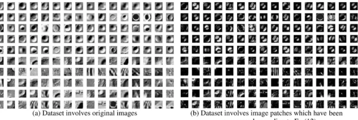
4.1. MatLSSVM-based crater classification experiment Unlike face recognition research in which the evaluation of recognition algorithm is constructed on the benchmark data-sets, there are no standard datasets to evaluate crater classifi-cation. Many algorithms are evaluated in a specific way by the authors using their own metrics and datasets. Fortunately, very recent proposals, methods and toolboxes from Internet are being presented to change this situation. For instance, Google Mars offers a mass of images of Martian surface. In this paper, the dataset for experiments comprises 160 image patches obtained from Google Mars (Fig. 4). This set contains 80 gray images of craters, 80 gray images of non-craters which are mainly composed of CCRs obtained by KLT-based meth-od and containing non-crater, and each image size is normal-ized to 20·20. Before all of the images in the dataset are used directly as input patterns of the proposed method for training and testing, they must be preprocessed by Eq.(12).
In experiments, the dataset is randomly divided into the two no-overlapping parts with the one as the training sample and the other one as the test sample. For each experiment in this section, ten independent runs are performed and their detection accuracies on the test sets are reported.
4.1.1. Comparison of the classification accuracies between the original samples and the preprocessed samples
In the crater classification algorithm based on matrix pattern, the parameters that should be set include the iterative count, the initial value of right weight vectorv0, learning rategand
the regularization constantC. This experiment sets the itera-tive count to 100, the regularization constant to 26, and the learning rate to 1. The initial value of right weight vector can be initialized with an arbitrary vector, but for simplicity we selectv0¼ ½1 1 . . . 1
T
inspired by Ref. 20. The kernel function chooses the linear kernel which is the simplest.Table 1
demonstrates accuracy rates in 10 independent runs on differ-ent image patterns, including original images obtained from Google Mars directly and preprocessed images which have been preprocessed according to Eq. (12), under the above experimental conditions. The results show that preprocessing of image patch before training and testing for eliminating ef-fects of different overall average brightness and contrast can improve accuracy rate of crater classification.
The left and right side of ‘‘+’’ are the numbers of correct detection in positive and negative testing samples respectively.
4.1.2. Comparison of classification accuracies between the vector input pattern and the matrix input pattern
This experiment examines matrixization effect by comparing with the method first introduced by Wetzler et al.12which is based on vector input pattern and SVM. The selection of parameters is the same as that of the above experiment.Table 2
demonstrates accuracy rates on different input patterns includ-ing vector pattern which is transformed from the image patch by the rule of row-to-column and matrix pattern which
repre-sents the image itself. The results show that although the per-formance of matrixization classifier is not very outstanding, the main advantage of this detection method is less space demanding compared with the approaches of vector pattern, and it gives a new idea which can use image itself directly for crater detection.
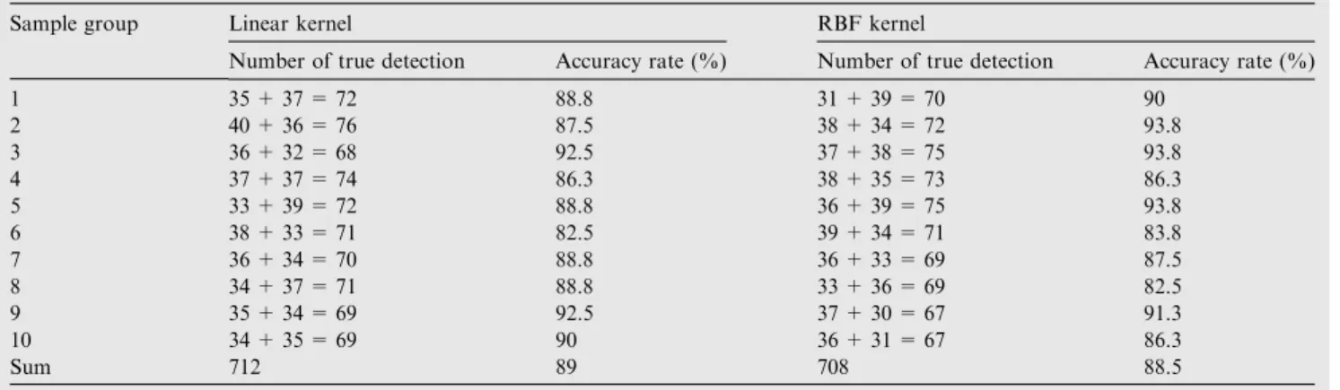
4.1.3. Comparison of detection accuracies between the linear and radial basis function kernel of SVM
The selection of kernel function and relative parameters is very difficult in pattern recognition. This experiment discusses the effect of different kernel functions including linear and radial basis function (RBF) kernel on accuracy rate. RBF kernel is expressed as follows:
K xi;xjÞ ¼expðcjjxixjjj2
ð13Þ The selection of parameters is the same as that of the above experiment and RBF parameter is set to 10. Table 3 demon-strates accuracy rates of methods which employ linear and RBF kernel functions respectively. The results show that differ-ent kernel functions have no obvious effect on accuracy rates.
In view of crater classification, we also make a comparison of accuracy rates between different values of parameters which are particular in the matrixization version of SVM, such as iterative count. As you know, the main disadvantage of
Fig. 4 Dataset for the experiments of crater classification algorithm which comprises 160 images.
Table 1 Accuracy rate comparison of different image patterns.
Sample group Original image pattern Preprocessed image pattern
Number of true detection Accuracy rate (%) Number of true detection Accuracy rate (%)
1 27 + 28 = 55 68.8 37 + 36 = 73 91.3 2 30 + 29 = 59 73.8 38 + 37 = 75 93.8 3 32 + 26 = 58 72.5 32 + 39 = 71 88.8 4 32 + 32 = 64 80 37 + 37 = 74 92.5 5 32 + 29 = 61 76.3 38 + 35 = 73 91.3 6 30 + 29 = 59 73.8 37 + 35 = 72 90 7 33 + 25 = 58 72.5 35 + 35 = 70 87.5 8 35 + 22 = 57 71.3 37 + 34 = 71 88.8 9 35 + 16 = 51 63.8 33 + 38 = 71 88.8 10 30 + 31 = 61 76.3 38 + 33 = 71 88.8 Sum 583 72.9 721 90.1
MatLSSVM-based approach is the price of an iterative imple-mentation. Therefore, in this experiment, we discuss the rela-tionship between accuracy rate and iterative count, choose the linear kernel function, the regularization constant equals to 26,v0¼ ½1 1 . . . 1T, learning rate is 1, and the variance range of iterative count is from 10 to 1000.Fig. 5shows the variance of accuracy rates in accordance with different itera-tive count respecitera-tively. Experimental results demonstrate that the accuracy rate is improved step by step as the iterative count is less than 100 and the variation range decreases to a stable level as the iterative count is more than 100.
4.2. Crater detection results
4.2.1. Relationship between eigenvalue thresholdkthand CCR selection
In the KLT detector for CCR selection, thresholdkthplays an important part.Fig. 6 shows the results of crater detection according to different thresholdkth. FromFig. 6, we can find that for bigger craters, KLT detector cannot select the entire CCR region but only parts of the region with increasing value of this threshold, and further leads to the detection error. The choice ofkthwill be discussed in the future.
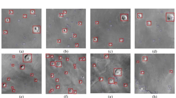
4.2.2. Experiment of crater detection
We choose eight zones of Martian surface as representative examples to evaluate this crater detection algorithm (shown inFig. 7). In fact, there is no standard procedure to evaluate and contrast different crater detection algorithms currently. Different algorithms employ different ways and used their own metrics and data sets. True detection rate (TDR) and false detection rate (FDR)5as well-established metrics are employed to assess the algorithm proposed in this paper.
TDRð%Þ ¼TR
GT100% ð14Þ
FDRð%Þ ¼ FD
TDþFD100% ð15Þ
Table 2 Accuracy rate comparison of different input patterns.
Sample group Vector pattern Matrix pattern
Number of true detection Accuracy rate (%) Number of true detection Accuracy rate (%)
1 35 + 36 = 71 88.8 36 + 35 = 72 90 2 36 + 34 = 70 87.5 38 + 37 = 75 93.8 3 36 + 38 = 74 92.5 37 + 38 = 75 93.8 4 37 + 32 = 69 86.3 36 + 33 = 69 86.3 5 35 + 36 = 71 88.8 39 + 36 = 75 93.8 6 33 + 33 = 66 82.5 34 + 33 = 67 83.8 7 38 + 33 = 71 88.8 38 + 36 = 74 87.5 8 37 + 34 = 71 88.8 37 + 33 = 70 82.5 9 37 + 37 = 74 92.5 34 + 39 = 73 91.3 10 36 + 36 = 72 90 36 + 33 = 69 86.3 Sum 709 88.6 719 89.9
Table 3 Accuracy rate comparison of different kernel functions.
Sample group Linear kernel RBF kernel
Number of true detection Accuracy rate (%) Number of true detection Accuracy rate (%)
1 35 + 37 = 72 88.8 31 + 39 = 70 90 2 40 + 36 = 76 87.5 38 + 34 = 72 93.8 3 36 + 32 = 68 92.5 37 + 38 = 75 93.8 4 37 + 37 = 74 86.3 38 + 35 = 73 86.3 5 33 + 39 = 72 88.8 36 + 39 = 75 93.8 6 38 + 33 = 71 82.5 39 + 34 = 71 83.8 7 36 + 34 = 70 88.8 36 + 33 = 69 87.5 8 34 + 37 = 71 88.8 33 + 36 = 69 82.5 9 35 + 34 = 69 92.5 37 + 30 = 67 91.3 10 34 + 35 = 69 90 36 + 31 = 67 86.3 Sum 712 89 708 88.5
where GT is the total number of craters in the selected images (in this paper, GT denotes the number of craters which are contained inP20·20 CCRs and obtained by manual count-ing), TD the number of true detections and FD the number of false detections.Table 4shows TD, FD, GT, TDR and FDR ofFig. 7.
InFig. 7, blue rectangles denote CCRs and red rectangles denote detected crater regions. Fig. 8 shows the CCRs of
Fig. 7(h) obtained by KLT-based method in which there are
rocks, discontinuities instead of craters. The result of
Fig. 7(h) shows that the classifier of this paper can separate CCRs containing non-crater from all CCRs obtained by KLT-based method. Table 4demonstrates that MatLSSVM-based algorithm can detect crater regions effectively on the ba-sis of KLT-based crater candidate region selection.
Table 4 Assessment parameters.
Image GT TD FD TDR (%) FDR (%) a 6 6 0 100 0 b 7 7 0 100 0 c 5 5 0 100 0 d 3 3 0 100 0 e 10 10 0 100 0 f 20 19 1 95 5 g 7 7 0 100 0
h 5 4 1 80 20 Fig. 8 CCRs in which there are rocks, discontinuities instead of
craters.
Fig. 7 Experiment results of crater detection.
5. Conclusions
(1) The algorithm introduced in this paper contains two modules: selection of crater candidate regions and crater detection. The first module gives input matrix to classi-fier of the module of crater detection. Therefore, most non-crater patches in the original image are quickly rejected by crater candidate regions selection.
(2) This paper employs the matrixization version of least square SVM, MatLSSVM, which greatly reduces the computation compared with traditional SVM and stor-age space, compared with general LSSVM, to detect cra-ters. Taking resized CCRs as input pattern, we obtain a novel approach for crater detection and the correspond-ing competitive performance on real Martian images. (3) Crater candidate regions can be selected by KLT
detec-tor. In this paper, we find that threshold kth is very important in crater detection. In the future, we need to develop adaptive computation method of thresholdkth.
Acknowledgements
The authors are grateful to Google Mars for providing data. They would also like to thank the anonymous reviewers for their critical and constructive review of the manuscript. This study was co-supported by the National Natural Science Foundation of China (No. 61203170), the Fundamental Re-search Funds for the Central Universities (No. NS2012026), and Startup Foundation for Introduced Talents of Nanjing University of Aeronautics and Astronautics (No. 1007-YAH10047).
References
1. Matthies L, Maimone M, Johnson A, Cheng Y, Willson R, Villalpando C. Computer vision on Mars. Int J Comput Vision 2007;75(1):67–92.
2. Tompkins S, Pieters CM. Mineralogy of the lunar crust: results from Clementine.Meteorit Planet Sci1999;34(1):25–41.
3. Rodionova JF, Dekchtyareva KI, Khramchikhin AA, Michael SV, Ajukov SV, Pugacheva SG.Morphological catalogue of the craters of Mars. Noordwijk, The Netherlands: ESA-ESTEC; 2000.
4. Barlow NG. Revision of the catalog of large Martian impact craters. In:Proceedings of the 6th international conference on Mars, 2003, Pasadena, California, USA: IEEE; 2003. p. 3073–4. 5. Bue B, Stepinski T. Machine detection of Martian impact craters
from digital topography data. IEEE T Geosci Remote 2007;45(1):265–74.
6. Giulia T, Jacqueline LM, Atli BJ. Automatic extraction of ellipsoidal features for planetary image registration.IEEE Geosci Remote S2012;9(1):95–9.
7. Banderia L, Saraiva J, Pina P. Impact crater recognition on Mars based on a probability volume created by template matching. IEEE T Geosci Remote2007;45(12):4008–15.
8. Ding M, Cao YF, Wu QX. Method of passive imaging based crater autonomous detection.Chin J Aeronaut2009;22(3):301–6. 9. Honda R, Iijima Y, Konishi O. Mining of topographic feature
from heterogeneous imagery and its application to lunar craters. Lect Notes Comput Sci2002;2281:27–44.
10. Earl J, Chicarro A, Koeberl C, Marchetti PG, Milnes M. Automatic recognition of crater-like structures in terrestrial and planetary images. In: workshop on the role of volatiles and atmospheres on Martian impact, 2005, Maryland, USA: IEEE; 2005. p. 1319–20.
11. Kim JR, Muller JP, Gasselt SV, Morley JG, Neukum G. Automated crater detection, a new tool for Mars cartography and Chronology.Photogramm Eng Rem S2005;71(10):1205–17. 12. Wetzler PG, Honda R, Enke B, Merline WJ, Chapman CR, Burl
MC. Learning to detect small impact craters. In:Proceedings 7th IEEEWACV/MOTION, 2005, USA: IEEE; 2005. p. 178–84. 13. Martins R, Pina P, Marques JS, Silveira M. Crater detection by a
boosting approach.IEEE T Geosci Remote2009;6(1):127–31. 14. Sawabe Y, Matsunaga T, Rokugawa S. Automated detection and
classification of lunar craters using multiple approaches. Adv Space Res2006;37(1):21–7.
15. Chen SC, Zhu YL, Zhang DQ, Yang JY. Feature extraction approaches based on matrix pattern: MatPCA and MatFLDA. Pattern Recogn Lett2005;26(8):1157–67.
16. Liu K, Cheng YQ, Yang JY. Algebraic feature extraction for image recognition based on an optimal discriminant criterion. Pattern Recogn1993;26(6):903–11.
17. Yang J, Zhang D, Frangi AF, Yang JY. Two-dimensional PCA: a new approach to appearance-based face representation and recognition.IEEE PAMI2004;26(1):131–7.
18. Taylor JS, Cristianini N. Kernel methods for pattern analy-sis. Cambridge: Cambridge University Press; 2004.
19. Suykens JK, Vandewalle J. Least squares support vector machine classifiers.Neural Process Lett1999;9:293–300.
20. Wang Z, Chen SC. New least squares support vector machines based on matrix patterns.Neural Process Lett2007;26:41–56. 21. Tissainayagam P, Suterb D. Assessing the performance of corner
detectors for point feature tracking applications. Image Vision Comput2004;22(8):663–79.
22. Benedetti A, Perona P. Realtime 2-D feature detection on a reconfigurable computer.In: Proceedings of IEEE Conference on Computer Vision and Pattern Recognition, 1998, Pasadena, USA: IEEE; 1998. p. 586–93.
Ding Meng received B.S., M.S. and Ph.D. degrees from Nanjing University of Aeronautics and Astronautics in 2003, 2006 and 2010 respectively. Currently, he is a lecturer of NUAA. His main research interests are machine vision, guidance, navigation and control.