Strathprints Institutional Repository
Rafferty, John and Xu, Lie and Morrow, John (2015) Analysis of voltage
source converter-based high-voltage direct current under DC
line-to-earth fault. IET Power Electronics, 8 (3). 428–438. ISSN 1755-4535 ,
http://dx.doi.org/10.1049/iet-pel.2014.0302
This version is available at http://strathprints.strath.ac.uk/51158/
Strathprints is designed to allow users to access the research output of the University of Strathclyde. Unless otherwise explicitly stated on the manuscript, Copyright © and Moral Rights for the papers on this site are retained by the individual authors and/or other copyright owners. Please check the manuscript for details of any other licences that may have been applied. You may not engage in further distribution of the material for any profitmaking activities or any commercial gain. You may freely distribute both the url (http://strathprints.strath.ac.uk/) and the content of this paper for research or private study, educational, or not-for-profit purposes without prior permission or charge.
Any correspondence concerning this service should be sent to Strathprints administrator:
1
Analysis of VSC-based HVDC under DC line-to-earth Fault
, ,
1. School of Electronics, Electrical Engineering and Computer Science, Queen’s University Belfast, UK (email:
[email protected]; [email protected])
2. Department of Electronic and Electrical Engineering, University of Strathclyde, Glasgow, UK (email: [email protected]) Abstract—DC line faults on HVDC systems utilising Voltage Source Converters (VSC) are a major issue for multi-terminal HVDC systems in which complete isolation of the faulted system is not a viable option. Of these faults single line-to-earth faults are the most common fault scenario. In order to better understand the system under such faults, this paper analyses the behaviour of HVDC systems based on both conventional two-level converter and multilevel modular converter technology, experiencing a permanent line-to-earth fault. Operation of the proposed system under two different earthing configurations of converter side AC transformer earthed with converter unearthed, and both converter and AC transformer unearthed, was analysed and simulated, with particular attention paid to the converter operation. It was observed that the development of potential earth loops within the system as a result of DC line-to-earth faults leads to substantial overcurrent and results in oscillations depending on the earthing configuration.
1.0
Introduction
Plans have been proposed for the interconnection of various offshore wind farms into a HVDC based European Supergrid with the clear aim of satisfying a large portion of the power demand throughout Europe with renewable generation [1–3]. Due to the numerous control and network support capabilities offered, Voltage Source Converter (VSC) based HVDC (VSC-HVDC) transmission has become a widely acknowledged technology for carrying out such a task. Thanks to the system control capabilities of VSC, there is the potential to interconnect numerous VSC-HVDC lines into a single multi-terminal DC (MTDC) network that can allow the efficient pooling and dispatch of energy over a vast geographical area [4–6].
However, before such a system can become a reality, various technical challenges need to be overcome to ensure safe and stable system operation on a large scale. One of these most important issues still to be addressed is the control and protection of the system under DC fault conditions [7]. Conventional thyristor based HVDC transmission systems do not experience high levels of overcurrent as a result of DC line faults [8]. However, when DC faults occur on VSC systems, due to the discharging of any capacitors on the DC side and the feeding of AC fault current to the DC system via the converters’ anti-paralleling (freewheeling) diodes, very large overcurrent can be generated [9,10].
Current protection schemes for point-to-point VSC-HVDC systems involve disconnection of the faulted line via AC circuit breakers, isolating the DC system in its entirety. However, this is not a viable option for MTDC systems, due to the large transmission capacities involved, therefore it becomes necessary to quickly and reliably detect and isolate only the
faulted line, thus protecting the sensitive power electronics of the converter, while ensuring security of supply is maintained [7].
Isolation of a faulted DC line has been proposed by utilisation of DC circuit breakers (DCCBs) [11, 12]. However, the development of such breakers for high voltage applications has presented a problem for years since, unlike AC systems, there is no natural current zero within DC systems, therefore such a breaker would have to force the current to zero and dissipate the energy stored in the systems inductance [13, 14]. Mechanical HVDC interrupters currently employed in existing DC systems are limited not only in terms of rating, but also operational speed, with an interruption time in the order of several tens of milliseconds, too slow to protect the sensitive IGBTs post fault [14]. Proposed fast acting DCCBs utilising semiconductor technology, which can operate within a few milliseconds, can eliminate some of the problems associated with DC fault protection. Various prototypes are currently under development [14, 15]; although it will likely be some years before commercially reliable and economical DCCBs are in operation. Even with the advent of DCCBs, fast and reliable DC fault detection will be essential to provide adequate protection, as well as speedy restoration of the system post-fault [13]. To this end, a thorough understanding of the converters behaviour under various fault conditions will be advantageous to ensuring that the most efficient fault detection and protection protocols can be developed.
A significant amount of work has been carried out on analysing the control and operation of MTDC systems, including its voltage control and power dispatch capabilities, as well as the resiliency of such systems to onshore AC grid disturbances [4, 16]. In terms of DC faults, most of the work focuses on fault detection and isolation, either; through the use of DCCBs[11] or via utilization of existing AC circuit breakers and fast acting switches [17, 18]. Analysis of the effects of line-to-line faults, and a brief analysis of line-to-earth faults on VSC systems was carried out in [8, 18,]. However, considering that a single line-to-earth fault is the most likely fault scenario, a further in-depth analysis into the converters behaviour during such an occurrence could prove advantageous in improving the understanding of system operations.
Many future HVDC systems are likely to use multilevel modular converter (MMC) configurations [19-20] which have different characteristics compared to the conventional two-level VSC systems. In fact, some proposed MMC configurations have inherent DC fault blocking capabilities [20]. However, a thorough understanding of the conventional 2-level systems and the methodologies used can provide useful guidance for analysing systems with different converter topologies.
The objective of this paper is to provide further analysis of the behaviour of a VSC-HVDC converter during a DC line-to-earth fault for both two-level and MMC based systems. The paper is organised as follows. Section 2 illustrates the earthing configurations of the proposed VSC systems. Sections 3 and 4 analyse the system operation of two-level converters during line-to-earth faults for two different configurations: AC transformer earthed/DC link unearthed, and both AC transformer and DC link unearthed, respectively. The analysis for MMC systems with unearthed transformer and DC link is shown in Section 5 and, finally, Section 6 draws conclusions.
3
Due to the physical protection of a single HVDC cable (armoring, insulation etc.), and the separation distances between the positive and negative cables, a potential fault to a single line as a result of cable aging or other physical damage is a more likely fault scenario than a line-to-line fault.Unlike DC line-to-line faults, which experience total discharging of the DC link capacitor [8, 11], for line-to-earth faults the system fault current is dependent on the formation of current loops created by shared earths within the system. Thus the earthing configuration is the main factor in analysing system operation [8].
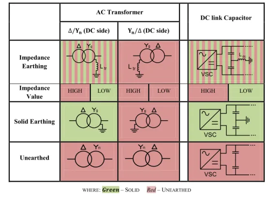
Table 1. Possible Earthing points of DC Converter System
AC Transformer DC link Capacitor (DC side) (DC side) Impedance Earthing g Ltr g Ltr VSC Ldc Impedance
Value HIGH LOW HIGH LOW HIGH LOW
Solid Earthing g g VSC Unearthed n n VSC
WHERE: – SOLID Red– UNEARTHED
MIXED–IMPEDANCE DEPENDANT (FROM THE CONVERTERS POINT OF VIEW)
Numerous earthing configurations on the converter stations are possible. Traditionally, earthing of the converter systems occurs at a number of possible points, e.g. the AC transformer neutral point, DC link capacitor midpoint, and/or each cable end [8]. No formalised specification for the earthing of MTDC systems has of yet been outlined [7]. Although implantation of various earthing configurations is currently carried out, the vast majority of existing systems are point-to-point. With regards to MTDC systems there is little practical experience and, as such, an ideal earthing configuration is not well defined. This could prove particularly challenging with regards to the proposed Supergrid, which could potentially incorporate converters with varying earthing configurations based on the criteria of the local system operator.
Although earthing of the AC transformer is usually on the AC grid side (unearthed from a converter point of view), work has been proposed on utilising an earthed Y connection on the converter side of the AC transformer, with an aim to help limit the peak line-to-line DC overvoltage caused by single-phase-to-earth faults on the converter side and, also, to allow the rebalancing of the positive and negative lines post fault [21]. In this study, the earthing configurations are presented for their merits which could help practitioners to overcome the limitations of those with sufficient technical benefits.
Additionally, the type of earthing used also plays a key factor in the systems behaviour [22]. The two available options, each with their own benefits and shortcomings, are:
a) High Impedance – limits the fault current. If a high enough value of impedance is used, the system can behave as if unearth.
b) Low Impedance (Solid) – doubles the pole-to-earth voltage on the healthy line during fault [7].
The potential earthing points within the converter system are outlined in Table 1. Despite the number of potential earthing configurations achievable, in this paper, detailed analysis of two configuration schemes, where each DC cable is earthed, are considered, i.e.
S1: converter side AC transformer earthed and DC link unearthed.
S2: both converter side AC transformer and DC link unearthed.
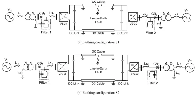
To assist the analysis of converter behaviour under potential earthing schemes for meshed networks, this paper focuses on the behaviour of a single converter, thus the two-terminal HVDC systems shown in Fig. 1(a) and (b), using 2-level converters with relatively large DC capacitance on each side, for the two different earthing configurations are represented.
g V1 L1 Ls1 Ls2 L2 V2 g Line-to-Earth Fault CB1 CB2
DC Link DC Cable DC Link Filter 2
Filter 1
Ltr1 VSC1 VSC2 Ltr2
DC Cable
(a) Earthing configuration S1
g V1 L1 Ls1 Ls2 L2 V2 g Line-to-Earth Fault CB1 CB2
DC Link DC Cable DC Link Filter 2
Filter 1
Ltr1 VSC1 VSC2 Ltr2
DC Cable
(b) Earthing configuration S2
Fig. 1. Two-terminal VSC-HVDC system with DC cable line-to-earth Fault, with AC transformer earthed on the (a) Converter side, and (b) the grid side.
D1 D2 D3 D5 D6 D4 va vb vc TA+ TB+ TC+
Voltage Source Converter
Vdc DC Link Ls idc icab ic DC Cable DC Cable LC R Ccabp LC R ia ib ic Ls Ls TC- TB- T A-Vcabn Ccabn Vcabp Breakers Ccabp Vcabp Vcabn Ccabn Ltr Cdc
5 D1 D2 D3 D5 D6 D4 va vb vc TA+ TB+ TC+
Voltage Source Converter
Vdc DC Link Ls idc icab ic DC Cable DC Cable LC R Ccabp LC R ia ib ic Ls Ls TC- TB- T A-Vcabn Ccabn Vcabp Breakers Ccabp Vcabp Vcabn Ccabn Cdc (b) VSM LM iA VSM LM iSM Vd Sub-module Voltage (V) Sub-module Current (i) MMC Arm Inductance (mH) iA Phase Current (Phase A) (A)
Sub-module Capacitor Voltage (V) Single Sub-Module D1 D2 D3 D5 D6 D4 va vb vc
Simplified Blocked MMC Model
Vdc Ls Ls Ls idc icab ic DC Cable DC Cable LC R Ccabpf LC R Ccabnf ia ib ic LM Ccabp Ccabn LM LM LM LM LM Total Arm Sub-Modules Equivalnet Breakers Vcabp Vcabn Vdc1 Vdc2 S2 Ds2 S1 Ds1 Vd C0 iSM (c) (d)
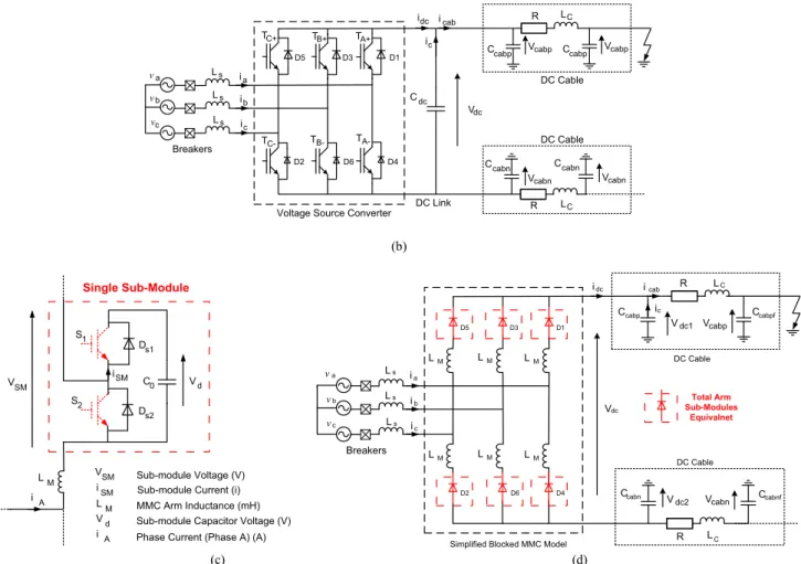
Fig. 2. Simplified system layout during a line-to-earth fault with: (a) Earthing configuration S1; (b) Earthing configuration S2; (c) Single sub-module for MMC; (d)Equivalent Converter layout of blocked MMC.
Analysis of a single VSC within the system is provided based on the equivalent circuit model shown in Fig. 2(a) and (b) for earthing schemes S1and S2, respectively. In the subsequent simulation studies, a permanent single line-to-earth fault occurs at t=0.5s on the positive DC line of the system between the sending and receiving end converters. The system is rated at ±250kV/500MW with an AC source voltage at the converter terminal of 260kV. A line inductance ( ) of 40mH and DC capacitance ( ) of F are used. Although a more detailed cable model would be required to analyse the cable current oscillation in greater detail, this paper focuses on providing a better understanding of the converters operation during single DC cable faults. With this in mind an RLC model of the cable based on [23] is used. Although this will not allow an exact analysis of the system response during a fault, it will allow understanding of its behaviour in more detail. The behaviour of the converter utilising the simplified cable model is comparable to its behaviour when a more detailed cable model is used, as will be illustrated in later sections. The lumped cable parameters are =215mH, R=5.80 , =9.92 [23]. Blocking of the IGBTs occurs at t=0.502s.
As previously stated, implementation of future MTDC system will likely be based on MMC technologies, which have many advantages over 2-level converters including the elimination of the common DC link capacitance which results in a significant reduction in the DC fault current produced [10]. Although there are a number of proposed topologies for
multi-level converters, to keep the system in line with existing MMC systems a Half-bridge topology will be used in this example [24].
Although the structure of 2-level VSCs and MMCs are completely different, blocking of the converter IGBTs post-fault is common to both. When this occurs, the sub-module capacitors in the MMC are quickly bypassed and the circuit can be effectively model using diodes, as shown in Fig. 2(c) which represents a single blocked sub-module. Thus the model of the MMC after the blocking of the IGBTs is comparable to the VSC model from Fig. 2(b), however with the inclusion of the additional arm inductance ( ), as shown in Fig. 2(d). It should be noted that although there is no additional DC link capacitors, the converter end cable capacitance values and are now considered as part of the DC cable, which will remain earthed at each end, with in this study. The cable capacitance now being analysed is the cable capacitance at the point of the fault and as shown in Fig. 2(d).
3.
S1: AC Transformer Earthed/DC Link Unearthed
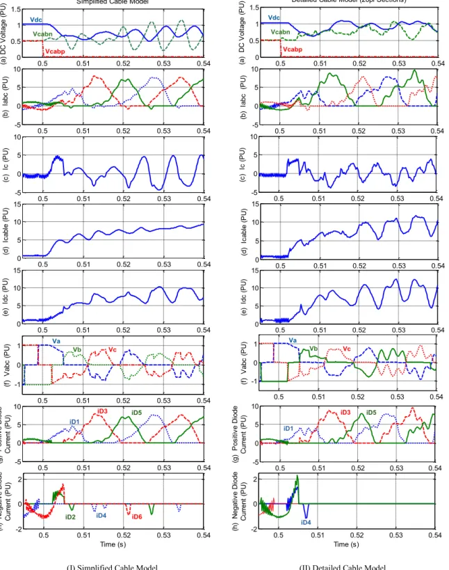
For earthing configuration S1 the converter system is modelled as shown in Fig. 2(a). Fig. 3 shows the simulation results during a single line-to-earth fault occurring at t=0.5s. The results shown in Fig. 3(I) were obtained using a simple one PI-section cable model whereas Fig. 3(II) are the results using a 20 PI-PI-section cable model. As can be observed, although the detailed oscillations are different, the general trends for the two different cable models are comparable. Therefore the use of simple cable model can provide simple yet valid means for analysing the converter system behaviour. Thus the detailed analysis that will be carried out in the following sections uses the simple cable model.
7 0.5 0.51 0.52 0.53 0.54 0 0.5 1 1.5
Simplified Cable Model
Time (s) (a ) D C V o lt a g e ( P U ) 0.5 0.51 0.52 0.53 0.54 -5 0 5 10 Time (s) (g ) P o s it iv e D io d e C u rr e n t (P U ) Vdc Vcabn Vcabp 0.5 0.51 0.52 0.53 0.54 -5 0 5 10 Time (s) (b ) I a b c ( P U ) 0.5 0.51 0.52 0.53 0.54 -5 0 5 10 Time (s) (c ) I c ( P U ) 0.5 0.51 0.52 0.53 0.54 0 5 10 15 Time (s) (d ) I c a b le ( P U ) 0.5 0.51 0.52 0.53 0.54 0 5 10 15 Time (s) (e ) I d c ( P U ) iD1 iD5 iD3 0.5 0.51 0.52 0.53 0.54 -2 0 2 Time (s) (h ) N e g a ti v e D io d e C u rr e n t (P U ) iD4 iD2 iD6 0.5 0.51 0.52 0.53 0.54 -1 0 1 (f ) V a b c ( P U ) Va Vb Vc 0.5 0.51 0.52 0.53 0.54 0 0.5 1 1.5 Time (s) (a ) D C V o lt a g e ( P U
) Detailed Cable Model (20pi Sections)
Vdc Vcabn Vcabp 0.5 0.51 0.52 0.53 0.54 -5 0 5 10 Time (s) (b ) I a b c (P U ) 0.5 0.51 0.52 0.53 0.54 -5 0 5 10 Time (s) (c ) I c ( P U ) 0.5 0.51 0.52 0.53 0.54 0 5 10 15 Time (s) (d ) I c a b le ( P U ) 0.5 0.51 0.52 0.53 0.54 0 5 10 15 Time (s) (e ) I d c ( P U ) 0.5 0.51 0.52 0.53 0.54 -1 0 1 (f ) V a b c ( P U ) Va Vb Vc 0.5 0.51 0.52 0.53 0.54 -5 0 5 10 Time (s) (g ) P o s it iv e D io d e C u rr e n t (P U ) iD1 iD5 iD3 0.5 0.51 0.52 0.53 0.54 -2 0 2 Time (s) (h ) N e g a ti v e D io d e C u rr e n t (P U ) iD4
(I) Simplified Cable Model (II) Detailed Cable Model
Fig. 3 Simulated waveforms during line-to-earth fault: DC link unearthed/AC transformer earthed (S1), with freewheeling diode current through (g) top diode group (D1, D3, and D5 ), and (h) bottom diode group (D2, D4, and D6).
3.1
Initial Operation
Initially, when the fault occurs, the positive DC line capacitance ( ) is shorted to earth causing an immediate drop in its voltage ( ) to zero as show in Fig. 3(a). This causes the DC voltage ( ) of the DC link capacitor ( ) to drop quickly, resulting in a significant rise in DC fault current at the DC link capacitor ( ) and DC cable ( ), and hence, the AC current at the AC terminals ( ), as can be observed in Fig. 3(a) and (b) and Fig. 3(c) and (d), respectively. The IGBTs are quickly blocked but the AC fault current continues increasing through the converter freewheeling diodes (Fig. 3(b)),
resulting in the subsequent rise in the DC current ( ) (Fig. 3(d) and (e)). The negative DC cable capacitor ( ), which was previously operating at -250 kV, begins to charge but becomes highly oscillative due to the oscillation of the AC fault current and the current loops formed by the shared earths within the system as can be observed in Fig. 3(a), where is the negative DC cable capacitance voltage.
The operation of the system under this scenario can be analysed in two operational modes i.e. positive diodes conducting via D1, D3, and D5, and negative diode conducting via D2, D4, and D6.
3.2
Positive Diode Conduction Operation
For the majority of the systems operation the freewheeling diodesD1, D3, and D5 of the converter act like a half-wave bridge rectifier permitting the flow of AC current to the DC system, as show in Fig. 3(b).
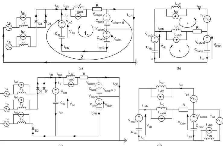
Two separate current loops form within the system, the first being between the AC source and the DC fault, created as a result of the shared earth between the two system components. The second current loop is created between the DC terminal and the DC cable and is the result of the charging/discharging of the DC link capacitors and the DC cable capacitance. After the initial fault, the half wave rectification of the AC current by the diodes results in current flowing through and in this particular example, thus the system resembles Fig. 4(a), where , are the AC source inductance, and cable inductance and resistance, respectively. The equivalent circuit for system operation during this initial positive phase, as shown in Fig. 4(a), can be represented in Fig. 4(b) and:
(1a)
and (1b) where and are the total AC source voltage and inductance, respectively. , are the total initial AC source current, and the initial voltages at the DC link and DC cable capacitance, respectively.
Due to the current loop formed between and , both capacitors go through a sequence of recharging and discharging in an attempt to reach equilibrium, resulting in the subsequent oscillation of , and , and continued oscillation of and , as observed in Fig. 3(a) respectively. However, because and are connected in series, the smaller of the two (i.e. by approximately 40% in this case) is the dominant capacitor, and as such the oscillation of is greater than that of . It should be noted that the direction of the voltage oscillations is the inverse of the other in each instance due to the different current directions relative to the capacitor voltages.
9 vT Icab0 Ccabn R Is0 LC Vcabn0 iCF iC icab idc 1. 2. Vdc0 Cdc LsT Vdc Vcabn Icab0 LC vb LS R Cdc Vdc0 Ccabn Vcabp0 Ib0 idc ic icab iCF iCN iCFN D3 va Ia0 LS D1
1.
2.
Vdc Vcabn Ccabp Vcabp Vcabn0 = 0 (a) (b) (c) (d)Fig. 4. Equivalent circuits during line-to-earth fault: (a) Initial AC positive diode conduction system, (b) Simplified circuit for positive system operation, (c) Negative diode conduction system, and (d)Simplified circuit for negative system operation
3.3
Negative Diode Conduction Operation
Due to the large AC network inductance ( ) the voltage at the converter AC terminals ( is usually low. However, for the majority of the time this terminal voltage still exceeds as can be observed in Figs. 3(a) and (f), resulting in predominantly positive diode conduction occurring thus the current is rectified through at least one of the diodes D1, D3, or D5.
However, due to the oscillation of and the increase of , due to the charging of , can occasionally become less than the AC terminal voltage as can be observed in Fig. 3(a) and (f), respectively. This creates a voltage potential between the AC and DC system and causes the flow of the AC current through one of the negative diodes (initially ). This is shown by the smaller negative current in Fig. 3(b) at approximately t=0.507–0.508s and will be further addressed in the following sections.
This results in an alteration of the system configuration as the system now resembles Fig. 4(c) with:
(2) Due to the alteration in system configuration caused by the current flowing through the negative diode ( ), the system under negative diode conduction operation can be represented by Fig. 4(d), where, and , and and , are the sum of the AC voltages and inductances connected to the positive and negative cables, respectively. Therefore, for the initial negative phase operation (3) is met.
(3)
3.4
State Oscillation Analysis
Oscillation of the system current results in the conduction of different combinations of the freewheeling diodes, altering the configuration of the system model. The sequence of diode conduction, and hence the systems operation, is dependent on the AC and DC voltages.
Oscillation between the different system configurations forms a repeating sequence, as can be observed in Figs. 3(a)–(f). Therefore, analysis of the system over a brief time period (0.025s post-fault) is a good interpretation of the total system operation. To more easily show the flow of current through each freewheeling diode, Figs. 3(g) and (h) show the current flow through the top diodes (iD1, iD3, and iD5) and the bottom diodes (iD2, iD4, and iD6).
Initially, after the blocking of the IGBTs at t=0.505s, the system operates as shown in Fig. 4(a) (positive diodes conducting), with and on as shown in Fig. 3(g), and (1a) is met for the equivalent circuit (Fig. 4(b)). At t=0.507s, begins conducting as negative current flows through the converter, due to the voltage potential created, as shown in Fig. 3(h). The system operates as shown in Fig. 4(d) (negative diodes conducting) where (2) is met. The sequence of the diode conduction over the initial period of time (0.025s) is shown in Table 2.
As can be observed from Table 2, the system occupies a number of different states (A – E) throughout this time period. System analysis for each state is shown below. Notation (n) indicates that negative diodes conduction is occurring; otherwise only the positive diodes are conducting. System configuration corresponding to the equivalent positive (Fig. 4(b)) and negative conduction circuits (Fig. 4(d)) are shown in Tables 3 and 4 respectively.
TABLE 2DIODE SWITCHING SEQUENCE
Time (s) Phase Voltage Phase Current +Ve Diodes -Ve Diodes Start End A B C A B C 1 3 5 2 4 6 A 0.5 0.5065 + + + + + 0 X X - - - - A(n) 0.5065 0.5075 0 + - + + - X X - X - - A 0.5075 0.5115 + + + + + 0 X X - - - - B 0.5115 0.5125 + 0 + + + 0 - X - - - - C(n) 0.5125 0.5135 - + + - + + - X X - X - C 0.5135 0.515 + + + 0 + + - X X - - - C(n) 0.515 0.516 - + + - + + - X X - X - C 0.516 0.518 + + + 0 + + - X X - - - D 0.518 0.5195 0 0 0 + + + X X X - - - E 0.5195 0.5205 + + + + + + X - X - - - E(n) 0.5205 0.5215 + - 0 + - + X - X - - X E 0.5215 0.525 + + + + 0 + X - X - - - where :X–Diode‘ON’ – –Diode‘OFF’
11
TABLE 3 EQUIVALENT CIRCUIT VALUES:POSITIVE STATES State A B C D E
TABLE 4 EQUIVALENT CIRCUIT VALUES:NEGATIVE STATES State
A(n) C(n) E(n)
As can be observed in Fig. 4(d), the complexity of the equivalent circuit for the system during negative operation is significantly increased when compared to the equivalent circuit for positive operation (Fig. 4(b)), due to the increased number of sources. However, as shown in Fig. 3(h), the short time period of negative conduction, as well as its small current magnitude, compared to the positive diode conduction cycle, means that this phenomenon can be neglected without causing significant errors. Further, when the detailed cable model is considered (Fig. 3(II)(h)), the negative diode conduction phenomenon is greatly reduced when compared to the simplified cable model, thus reinforcing the notion that neglecting the negative diode cycle incurs little error on the overall system analysis.
0.5 0.51 0.52 0.53 0.54 0 0.5 1 1.5 Time (s) (a ) D C V o lt a g e ( P U ) Vdc Vcabn Vcabp 0.5 0.51 0.52 0.53 0.54 -5 0 5 Time (s) (b ) I a b c ( P U ) 0.5 0.51 0.52 0.53 0.54 -5 0 5 10 Time (s) (c ) I c ( P U )
Fig. 5 Simulated waveforms during line-to-earth fault: both DC link AC transformer unearthed
4
S2: Both DC Link and AC Transformer Unearthed
In this scenario we assume that the AC transformer is now unearthed on the converter side with the DC link capacitor remaining unearthed, thus the system is now as shown in Fig. 1(b). In this case, the DC cable ends are still earthed thus one terminal of the system is as shown in Fig. 2(b). The system behaviour for the entire fault timeline is shown in Fig. 5.
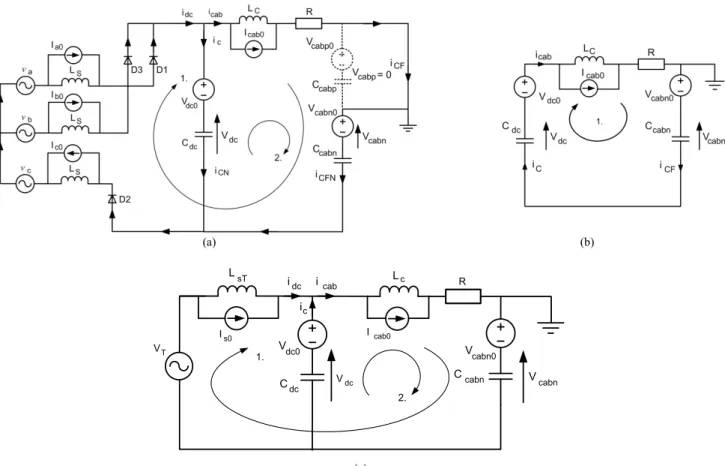
In this scenario the lack of an earthing point on the converter side isolates the AC and DC systems. As with the previous example, the fault results in the discharging of the DC link capacitors resulting in a reduction of the DC voltage (Fig. 5(a)) and the subsequent rise in the DC fault current as observed in Fig. 5(c)–(e). Initially, the system resembles Fig. 6(a).
However, because there is no common earth between the AC and DC systems, as begins to recharge (as in the previous example) the DC voltage of the system is quickly restored to approximately 1.0pu by t=0.51s, resulting in an elimination of any voltage potential between the AC and DC systems, thus reducing the AC fault current and, hence, reduces to zero as observed in Fig. 5 (b) and (e) with the equivalent system now resembling Fig. 6(b).
This elimination of the AC fault currents contribution to the system greatly reduces the DC fault current when compared to the previous example as observed in Fig. 3(c)–(e) and Fig. 5(c)–(e). However, due to the formation of current loops within the DC system and continue to oscillation as a result of the oscillation of and , due to the recharging and discharging of and as observed in Fig. 5(c) and (d) at t=5.1s.
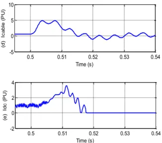
0.5 0.51 0.52 0.53 0.54 -5 0 5 10 Time (s) (d ) I c a b le ( P U ) 0.5 0.51 0.52 0.53 0.54 -2 0 2 4 Time (s) (e ) I d c ( P U )
13 (a) (b) Cdc Ccabn Vdc0 Vdc Icab0 Is0 idc icab ic VT V cabn0 R V cabn LsT Lc 1. 2. (c)
Fig. 6 (a) Initial System configuration during line-to-earth fault with converter and AC transformer unearthed; (b) Equivalent circuit on the DC side; and (c) Simplified circuit for initial AC feeding Stage
4.1
State Oscillation Analysis
As in the previous example, the system configuration changes as the sequence of diode conduction changes dependant on the AC current. Unlike the previous example, this does not form a repeating sequence as the AC overcurrent is reduced to zero by t=0.5178s due to the lack of a shared earth (Fig. 5(b)). The sequence of diode conduction for the initial AC current feeding stage is as given in Table 5, with the system configuration at each stage corresponding to the equivalent circuit for the initial feeding phase (Fig. 6(c)) is as shown in Table 6.
TABLE 5DIODE SWITCHING SEQUENCE:AC TRANSFORMER UNEARTHED/DC LINK UNEARTHED
Time (s) Phase Voltage Phase Current +Ve Diodes -Ve Diodes Start End A B C A B C 1 3 5 2 4 6 A 0.5 0.507 + + - + 0 - X - - X - - B 0.507 0.509 0 + - + + - X X - X - - C 0.509 0.511 - + - 0 + - - X - X - - D 0.511 0.513 - + 0 - + - - X - X X - E 0.513 0.514 - + + - + 0 - X - - X - F 0.514 0.516 - 0 + - + + - X X - X - G* 0.516 0.5162 - - + 0 0 0 - - - - - H 0.5162 0.5178 0 - + - - + - - X - X X G* 0.5178 - - - + 0 0 0 - - - - - -
TABLE 6EQUIVALENT CIRCUIT VALUES State A B C D E F G* H G*
For state (Table 6), the AC overcurrent has extinguished, due to the restoration of to 1pu as can be observed in Figs. 5(a) and (b). This system at this time is as represented in Fig. 6(b).
In such a case, detection of the fault could potentially be hindered due to no significant AC fault current and, subsequently, significantly lower DC fault current being produced. Fault detection in this case would need to rely on other measurements, e.g., detection of the DC pole under/over voltage.
4.2 Discussion of Differing Earthing Configurations
As can be observed in Sections 3 and 4, the systems behaviour during line-to-earth faults is dependent on the earthing configuration employed. Both systems S1 and S2 experience substantial overcurrent due to the discharging of the DC link capacitors as can be observed in Figs. 3 and 5. However, behaviour of the converter is noticeably different in each case.
S1 - Substantial AC overcurrent occurs in a characteristic half-wave rectification pattern and continues to feed the DC system for the duration of the fault timeline (until isolation of the converter via DC or AC CBs), due to shared earthing between the converter side AC transformer and DC system. Also, the DC voltage is not restored to normal levels for the duration of the fault (Fig. 3).
S2 – AC and DC overcurrent is not as pronounced as S1 (although still substantial during the initial fault stage), and AC overcurrent is quickly extinguished due to the lack of a shared earth between the converter side AC transformer and DC system, thus the DC fault current is effectively reduced to zero within a short period, e.g., 20 ms in the study. Even without isolation of the faulted line, the DC voltage is restored to approx. 1pu (Fig. 5).
The differing behaviour of the converter for each earthing configuration is important, particularly the levels of overcurrent involved and their duration. This may need to be taken into account with regards to fault detection and protection protocols, especially for S2 since the overcurrent is relatively small (compared to S1) and quickly extinguished; also, the DC voltage within the system is effectively restored to normal levels within a short period (Fig. 5).
15 Ccabp Ccabnf Ccabn V cabn0 Vcabp0 Vdc Icab10 IMMC0 idc icab ic 2. 3. 1. Lc Icab20 R VT V cab0 LMMC Lc R V cabp V cabn Vcabnf
Fig. 7 Equivalent circuit for initial MMC operation during a Line-to-Earth fault
5
DC Line-to-Earth fault: Half-Bridge MMC
The equivalent circuit for initial MMC operation during a line-to-earth fault can be derived in a similar way as for 2-level converters and it is now shown in Fig. 7 where the MMC arm and cable inductances are lumped into a single parameter as
(9a) (9b) where, and are the MMC arm inductance and its initial current respectively.
Only the configuration of the AC transformer secondary side unearthed (similar to the case in Section 4) is considered due to space constraints. Full analysis of the systems response can be achieved by utilising the analytical method from Sections 3 and 4. Due to the space limitation it is not provided here. Simulation results for the systems behaviour is shown in Fig. 8.
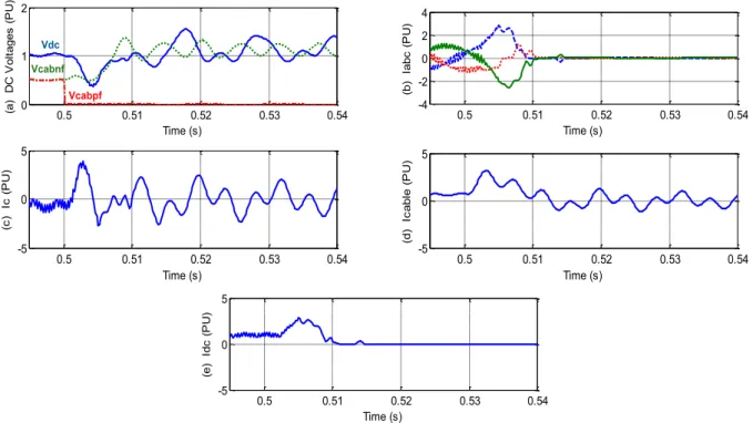
In such a scenario the earthing of the DC cable ends provides a pathway for the DC overcurrent after the initial fault. As with the previous example the discharging of results in a drop in to 0.5pu (Fig. 8(a)), causing the AC and DC fault current to increase substantially (Figs. 8(b)–(d)). However, similar to the previous analysis for 2-level converters, the negative DC cable is quickly charged and the total DC voltage recovered, causing to fall to zero within 0.02s (Fig. 8(e)). Consequently, the AC current is also reduced to zero, as shown in Fig. 8(b) by t=0.52s.
After the initial overcurrent the converter itself would experience little fault current. Due to the formation of an earth loop between the two ends of the DC cable and the fault, current still flows within the cable as can be observed by the fluctuation of and as shown in Figs. 8(c) and (d), at t=0.525s.
0.5 0.51 0.52 0.53 0.54 0 1 2 Time (s) (a ) D C V o lt a g e s ( P U ) Vdc Vcabnf Vcabpf 0.5 0.51 0.52 0.53 0.54 -4 -2 0 2 4 Time (s) (b ) I a b c ( P U ) 0.5 0.51 0.52 0.53 0.54 -5 0 5 Time (s) (c ) I c ( P U ) 0.5 0.51 0.52 0.53 0.54 -5 0 5 Time (s) (d ) I c a b le ( P U ) 0.5 0.51 0.52 0.53 0.54 -5 0 5 Time (s) (e ) I d c ( P U )
Fig. 8 Simulated waveforms during line-to-earth fault on MMC
As can be observed from Figs. 5 and 8, behaviour of the VSC and MMC system with DC link unearthed/AC transformer unearthed are comparible post fault, with similar AC and DC overcurrent, and AC current oscillation due to the formation of similar earth loops within the system. However, the DC overcurrent levels are noticeable smaller for the MMC system due to the elimination of the large DC link capacitors.
6
Conclusions
This paper analyses the behaviour of a VSC-HVDC system under a DC line-to-earth fault, outlining system behaviour dependent on the earthing configuration. A detailed analysis of a VSC-HVDC system utilising two different earthing configurations i.e. unearthed DC converter with earthed AC transformer, and unearthed DC converter and AC transformer are provided. System operation at each stage of the fault was analysed during these fault scenarios and behaviour of the system during the entire fault timeline was also outlined. It was observed that the formation of earth loops within the system leads to substantial overcurrent through the converter and causes the system to oscillate between various different states. System behaviour is dependent on earthing scheme implemented and needs to be taken into account when developing operational procedures and fault detection and protection strategies.
DC fault behaviour of modular multilevel converter based HVDC system was also studied and found to be comparable to a conventional VSC system after the blocking of the converters in both cases. Despite the advantages offered, modular multilevel converters are still susceptible to faults in a similar manner to conventional VSC systems, however the reduced size of the DC link capacitance minimises the levels of fault current produced. Proposed development of multilevel converters with inherent fault blocking abilities and/or the development of commercial DCCBs is still a necessary
17
References
[1] “A European Supergrid: Evidence to the Energy and Climate Change Committee” IET, 31 March 2011 [2] “European Offshore Supergrid Proposal” Vision and Executive Summary, Airtricity 2006.
[3] “EU Energy Policy to 2050” European Wind Energy Association, March 2011.
[4] L. Xu, L. Yao; “DC Voltage Control and Power Dispatch of a Multi-Terminal HVDC System for Integrating Large Offshore Wind Farms” IET Renewable Power Gen., vol.5, no.3, pp.223-233, April.2011.
[5] L. Jiao, G. Joos, C. Abbey, F. Zhou, B. Ooi; “Multi-Terminal DC (MTDC) System for Wind Farms Powered by Doubly-fed Induction Generators
(DFIGs)” 35th Annual IEEE Power Electronics Specialists Conference, June 2004.
[6] T. Haileselassie, M. Molinas, T. Undeland; “Multi-Terminal VSC-HVDC System for Integration of Offshore Wind Farms and Green Electrification
of Platforms in the North Sea” NORPIE/2008, Nordic Workshop on Power and Industrial Electronics, June 2008.
[7] D.Van Hertem, M. Ghandhari; “Multi-Terminal VSC for European Supergrid: Obstacles” Renewable and Sustainable Energy Reviews, vol.14, no.9, pp.3156–3163, July.2010.
[8] J. Ying, J. Fletcher, J. O’Reilly, “Short-Circuit and Ground Fault Analyses and Location in VSC-based DC Network cables” IEEE Trans. Industrial Electronics, vol.59, no.10, pp.3827-3837, Oct. 2012.
[9] Y.J. Ko, K.B. Lee, D.C.Lee, J.M. Kim, “Fault Diagnosis of Three-Parallel Voltage-Source Converter for a High-Power Wind Turbine,” IET Power Electron., Vol.5, Iss.7, pp.1058–1067, Aug. 2012.
[10] J. Rafferty, L. Xu, D. J. Morrow; “Analysis of VSC-based HVDC System under DC Faults,” IEEE Industrial Electronics Society Conf. (IECON13), pp.459–464, Nov. 2013.
[11] C.J. Creiner, T. Langeland, J. Solvik, O. A. Rui; “Availability evaluation of Multi-Terminal DC Networks with DC Circuit Breakers,” IEEE PowerTech conf., Trondheim, June.2011.
[12] C. M. Franck, “HVDC Circuit Breakers: A Review Identifying Future Research Needs,” IEEE Trans. On Power Delivery, vol.26, no.2, pp.998-1007, April.2011.
[13] C.D. Barker, R. S. Whitehouse, “An Alternative Approach to HVDC Grid Protection,” IET ACDC Conf. 2012, Birmingham, pp.1-6, Dec.2012. [14] J. Häfner, B. Jacobson, “Proactive Hybrid HVDC Breakers –A key Innovation for Reliable HVDC Grids,” Cigre Symposium on Electric Power
System of the Future, ref. 264, Bologna, Italy, Sept.2011.
[15] M. Callavik, A. Blomberg, J. Häfner, B. Jacobson, “The Hybrid HVDC Breaker,” ABB [online] available: http://www05.abb.com/global/scot/scot221.nsf/veritydisplay/c9d5ba256e7e9671c1257ab6004b1feb/$file/hybrid-hvdc-breaker---an-innovation-breakthrough-for-reliable-hvdc-gridsnov2012.pdf
[16] L. Xu, L. Yao, M. Barargan; “DC Grid Management of a Multi-Terminal HVDC Transmission System for Large Offshore Wind Farms”, Proc. First SUPERGEN'09 conf., Nanjing, China, April.2009.
[17] M. Baran, N. Mahajan, “Overcurrent Protection on Voltage-Source-Converter-Based DC Distribution Systems;” IEEE Trans. Power Delivery, vol.22, no.1, pp.406-412, Jan.2007.
[18] L. Tang, B. Ooi, “Locating and Isolating DC faults in Multi-Terminal DC Systems;” IEEE Trans. Power Delivery, vol.22, no.3, pp.1877-1884, July.2007.
[19] Y. Wan, S. Lui, J. Jiang, “Generalised Analytical Methods and Current-Energy Control Design for Modular Multilevel Cascade Converter,” IET Power Electron., Vol.6, Iss.3, pp.295–504, March 2013.
[20] M.M.C. Merlin, T.C. Green, P.D. Mictheson, D.R. Trainer, D.R. Critchley, R.W. Crookes; “A New Hybrid Multi-Level Voltage-Source Converter
[21] L. Tang, B. Ooi, “Managing Zero Sequence in Voltage Source Converter,” IEEE Industry Application Conf., Pittsburgh USA, vol.2, pp.795–802, Oct.2002.
[22] S. De Boeck, P. Tielens, W. Leterme, D. Van Hertem, “Configurations and Earthing of HVDC systems,” IEEE PES Gen. Meeting, Vancouver, July 2013.
[23] “Requirement Specification for a DC Network and a DC Breaker Prototype,” Twenties Project report, Section 4.4 Matlab Cable Modelling and Results, Page.38.
[24] H. Liu, P.C. Loh, F. Blaabjerg, “Review of Fault Diagnosis and Fault-tolerant Control for Modular Multilevel Converter of HVDC,” IEEE Industrial Electronics Society Conf. (IECON13), pp.1242–1247, Nov.2013.