Host Multicast: A Framework for Delivering
Multicast To End Users
Beichuan Zhang Sugih Jamin Lixia Zhang
Abstract—While the advantages of multicast delivery over ple unicast deliveries is undeniable, the deployment of the IP multi-cast protocol has been limited to “islands” of network domains un-der single administrative control. Deployment of inter-domain mul-ticast delivery has been slow due to both technical and administra-tive reasons. In this paper we propose a Host Multicast Tree Proto-col (HMTP) that (1) automates the interconnection of IP-multicast enabled islands and (2) provides multicast delivery to end hosts where IP multicast is not available. With HMTP, end-hosts and proxy gateways of IP multicast-enabled islands can dynamically create shared multicast trees across different islands. Members of an HMTP multicast group self-organize into an efficient, scalable and robust multicast tree. The tree structure is adjusted periodi-cally to accommodate changes in group membership and network topology. Simulation results show that the multicast tree has low cost, and data delivered over it experiences moderately low latency.
I. INTRODUCTION
An efficient and scalable multicast mechanism is essential to the success of large-scale group communication applications. IP Multicast [3] has long been regarded as the right mechanism for this due to its efficiency. In IP Multicast, a packet is sent once by the source, and reaches every destination without unneces-sary duplication in the network. However, since its deployment imposes dependency on routers, full deployment has been long in coming. Several alternate approaches to multicast delivery in the network have been proposed, e.g., Source-Specific Mul-ticast [10], Simple MulMul-ticast [15], etc. While these alternate approaches generally make improvements or simplifications to multicast delivery in some aspects, they do not improve upon traditional IP Multicast in terms of deployment hurdles. Not only do these alternate approaches have the same dependency on routers as does IP multicast, they further lack an installed base. Today’s IP Multicast is limited to “islands” of network domains under single administrative control or local area networks. Cur-rent deployment practices require using manual configuration of tunnels to connect these IP multicast enabled “islands” to form the MBone, a static overlay network. This approach relies upon coordinated manual configuration of multicast routers on both
Beichuan Zhang and Lixia Zhang are with Computer Science Depart-ment, University of California, Los Angeles, CA 90095, email: {bzhang, lixia}@cs.ucla.edu. This project is funded by NSF grant number ANI-9902925. Sugih Jamin is with the EECS Department, University of Michigan, Ann Ar-bor, MI 48109-2122, email: [email protected], and is supported by the NSF CAREER Award ANI-9734145, the Presidential Early Career Award for Scientists and Engineers (PECASE) 1998, and the Alfred P. Sloan Foundation Research Fellowship 2001.
ends of each tunnel, which makes the MBone expensive to set up and maintain. The lack of ubiquitous multicast support limits the development of multicast applications, which in turn reduces the incentive for network operators to enable multicast.
An alternative to router-dependent multicast service is to let end-hosts that form a multicast group to replicate and forward packets on behalf of the group. In this case the multicast func-tionality is moved from routers to end-hosts, from the network layer to the transport or application layer. End-host multicast de-ployment can thus be performed by end users or even automat-ically by application codes. However, doing multicast at end-hosts incurs some performance penalty. Generally end end-hosts do not have the routing information available to routers, instead they must rely on end-to-end measurements to infer network metrics upon which the end-host multicast delivery tree is built. There-fore routing in end-host multicast trees is inherently less efficient and end-host multicast protocol is generally less scalable to large groups.
We propose a hybrid multicast delivery framework to lever-age both approaches. We call this the Host Multicast frame-work. Our goal in designing the Host Multicast framework is to provide best-effort multicast delivery service to applications. We specify its first design criterion: to be fully deployable in the cur-rent Internet. This calls for an end-host based multicast delivery that does not depend on cooperation from routers, servers, tunnel end-points, and operating systems. The second design criterion is to be compatible with IP Multicast to the furthest extent pos-sible. Host Multicast supports the IP Multicast service model, it automatically uses IP Multicast where available. Applications running on top of the Host Multicast framework send and re-ceive native IP Multicast packets. Compatibility with IP Mul-ticast allows Host MulMul-ticast to take advantage of the scalability of IP Multicast where available, making Host Multicast itself more scalable. We hope that as the Host Multicast framework becomes more widely deployed it will in turn spur on further production of multicast application and further deployment of IP Multicast. In this way multicast support can gradually spread from the edges of the Internet into the core. To support large number of end-hosts and IP Multicast “islands,” Host Multicast must meet a third design criterion: to be scalable. The size of a multicast group should not be a limiting factor in Host Multicast routing. In the absence of IP Multicast, Host Multicast by itself should also be efficient, to kick start the virtuous cycle leading to ubiquitous availability of multicast service described above.
We propose a specific protocol to support the Host Multi-cast framework. We call this the Host MultiMulti-cast Tree Protocol (HMTP). The rest of the paper is structured as follows. We re-view related work on auto-tunneling and end-host multicast pro-tocols in Section II. In Section III we give an overview of Host Multicast design, followed by host extensions required by Host Multicast in Section IV. In Sections V, VI, and VII we present the design of HMTP and performance results from simulations of the protocol. Finally, we summarize in Section VIII.
II. RELATEDWORK
The MBone was designed to facilitate the deployment of IP Multicast. It connects IP Multicast islands using tunnels, obvi-ating IP multicast support on intermediate routers between the islands. The use of IP-in-IP tunnels means that the MBone re-quires support from the operating systems. Furthermore, setting up the tunnel end-points requires manual configuration and ad-ministrative privileges on routers. These factors make providing multicast delivery service an expensive proposition. UMTP [4] and mTunnel [13] propose to use UDP tunnels, whose deploy-ment does not require administrative privileges, instead of IP-in-IP tunnels. Additionally, the use of UDP tunnels enables appli-cations to send and receive native IP Multicast packets. Our Host Multicast design also uses UDP tunnels (see Section V). Auto-tunneling proposals focus on discovery of tunnel end-points. UMTP [5] uses an intermediate source-specific multicast (SSM) router to intercept group join requests sent to the source, and cre-ate tunnels on demand. AMT [17] uses dediccre-ated servers (gcre-ate- (gate-ways and relays) and IGMP to set up tunnels. AMT also sup-ports only SSM traffic. Castgate [11] uses a DNS-like hierarchi-cal, distributed database to support MBone tunnel management. All tunnel end-points must register themselves in the database. To join the MBone, a host/network first looks up the database for a “good” end point and establishes a tunnel to that end point. All the above proposals automate only the setup of static tun-nels. None of them support dynamic auto-reconfiguration of the MBone due to network changes. Furthermore, they all require operational support from routers or dedicated servers, which continues to undermine the deploy-ability of IP Multicast.
End-host multicast has minimal deployment barriers. Exist-ing end-host multicast protocols differ in their target applica-tions and routing algorithms. End-System Multicast [2] and ALMI [14] target collaborative applications with a small num-ber of group memnum-bers. Scattercast [1] is designed for global content distribution. It requires dedicated servers strategically placed around the Internet to support large number of clients. Yoid [6] is a set of protocols forming a new architecture for gen-eral content distribution. It inserts three layers of protocols: an identification protocol, a transport protocol, and a tree formation protocol between the transport and application layers. BTP [9] is a protocol to construct efficient multicast delivery tree.
The scalability and efficiency of end-host multicast largely de-pends on the quality of its distribution tree. The simplest way to
build an end-host multicast tree is to run a conventional rout-ing algorithm and build a shortest-path tree rooted at the source. This approach, however, generates a star topology rooted at the source, with a unicast connection between the source and each member. Obviously such a tree has serious scalability and ro-bustness problem near the source. In addition to a tree creation mechanism, an end-host multicast protocol must also handle dy-namically changing group memberships, hence a member dis-covery mechanism is also needed.
ALMI takes a centralized approach to the tree creation prob-lem. Members of a multicast group perform network measure-ments between themselves as a measure of distance. A controller collects this measurements from all members, computes a mini-mum spanning tree based on these measurements, and dissemi-nates routing tables to all members. The centralized nature of this protocol limits its scalability. End-System Multicast and Scattercast take a mesh-based approach. An overlay mesh is created to connect members of a multicast group. On this mesh a conventional routing algorithm is run to generate per-source
trees which are then used for multicast delivery. The
challeng-ing part of this approach is in determinchalleng-ing which link to keep, which to delete, and how to do both in an adaptive way. End-System Multicast and Scattercast use different functions to eval-uate the utility of a link, which is then used in deciding which link to keep. The advantages of this approach are that (1) exist-ing routexist-ing algorithms can be leveraged and (2) loop avoidance is built-in. However, in both protocols every member is required to keep a full list of all the other members. The needs for member discovery and maintenance of membership list limit these algo-rithms to support only small multicast groups. Another approach is the tree-based approach. Group members self-organize into a
shared tree by explicitly picking a parent for each new member.
This approach scales well to large group sizes because each host only needs to know of a small number of other hosts. However, the choice of parents determine the performance, and to a large degree the efficiency, of the resulting tree. It must also prevent loops and handle tree partition. Yoid, BTP, and HMTP all adopt this approach, but use different tree building algorithms. In ad-dition to the distribution tree, Yoid also creates a mesh structure connecting the members, to increase stability.
III. OVERVIEW A. Architecture
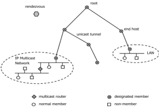
In Host Multicast, each group member runs a daemon process (Host Multicast agent) in user space. The daemon program pro-vides Host Multicast functionality at the end-host. An IP Multi-cast island is a network of any size that supports IP MultiMulti-cast. It can be a single host, an Ethernet, a campus network, etc. All end hosts are assumed IP-Multicast-capable—which is true for most modern operating systems. Within an island, native IP Multicast is used to send and receive data. One member host in an island is elected as the Designated Member (DM) for the island. Differ-ent islands are connected by UDP tunnels between DMs. These
PXOWLFDVURXWHU QRUPDPHPEHU XQLFDV XQQHO ,0XOWLFDV 1HWZRUN HQ KRVW /$1 GHVLJQDWH PHPEHU QRQPHPEHU URRW UHQGH]YRXV
Fig. 1. Host Multicast Architecture
tunnels are similar to the ones used in the mTunnel and UMTP protocols. Data encapsulated in UDP packets flow from one is-land to another through the tunnels. Upon reaching an isis-land, the data packets are de-capsulated by the DM, and then multi-cast onto the island. All DMs run HMTP to self-organize into a bi-directional shared tree.
On the shared tree, two members are neighbors if they are connected by a tunnel. A special node is assigned the root of the tree. The root has no parent. Every other node has exactly one neighbor as its parent. Non-parent neighbors are children. From the root to each member, there is only one, loop-free path along the tree. The member list of this path is called the root
path. Once a member is attached to the tree, it participates in
multicast delivery: incoming data packets from a neighbor are replicated and forwarded to all the other neighbors. Thus a data packet eventually reaches every node on the tree.
Each multicast group requires a Host Multicast Rendezvous Point (HMRP) where new members can learn about member-ships of the group and bootstrap itself. HMRP’s IP address is part of the group information, obtained off-line by the applica-tion. HMRP always knows which host is the root of the shared tree. New members query HMRP for the root, then starting from root they probe a small subset of members as potential parent. HMRP does not participate in data forwarding, so the location of HMRP has no significant impact on the performance of data dis-semination. One HMRP can serve multiple groups at the same time. It can be a single end host, a dedicated server, or a cluster of servers. Failure of HMRP will prevent new members from joining the group, but will not affect data dissemination among existing members. Group-wide features (policy, security, etc.) can be implemented at the HMRP.
B. Group Identifier and Session Directory
The IETF MALLOC working group has proposed a hierar-chical architecture [16] to dynamically allocate IP Multicast ad-dresses in the global scale, however its implementation and ployment will take time. For Host Multicast, we therefore de-cided to use class-D addresses within multicast islands. Between islands, groups are identified by a Group Identifier (GID). Each group has a 32-bit number serving as the group number. This group number is assigned by the group’s HMRP upon the cre-ation of the group and is unique per HMRP. The concatencre-ation
Application
Host Multicast Agent User Space
OS Kernel
IP Multicast to/from members in the same island
Unicast to/from other islands
encapsulation decapsulation
Application Application
IP Multicast Loopback
Fig. 2. How UDP tunnel works
of the HMRP’s IP address and the group number is the group’s GID, which is then globally unique. If a human-readable group name (e.g., www.cs.ucla.edu/myconference) is in use, HMRP will be responsible for resolving it to its GID. The group name or GID is obtained off-line by users or applications and passed on to the Host Multicast agent.
Within an island, local IP Multicast groups are used for data delivery and control. The mapping between GID and local IP Multicast groups is done by including session directory [8] functionalities (e.g., SDP, SAP, address allocation) in the agent. When an end host gets a GID and wants to join the group, its agent checks the session directory first. If there are existing IP Multicast groups associated with this GID, addresses of those groups are returned to the host. Otherwise, new IP Multicast groups are allocated and announced in the session directory. We assume that address allocation and session directory are avail-able within an island. How these services are realized (e.g., dy-namic or static address allocation, with or without SAP servers) is beyond the scope of this paper and is orthogonal to our design.
IV. HOSTEXTENSION
A basic function of the Host Multicast agent is to implement tunneling (Fig. 2). The DM’s agent maintains a list of groups in which the DM is interested, listens to the corresponding lo-cal IP Multicast groups, and establishes tunnels to other islands. Data packets originating from the local island are received via IP Multicast, encapsulated with a Host Multicast trailer, and sent to the other end of a tunnel as UDP packets. Data packets arriving from a tunnel are de-capsulated and sent to the corresponding local IP Multicast groups, so that all members in the same island will receive the packets. If the DM is no longer interested in a group, its agent tears down the tunnel for that group and stops listening on the corresponding local groups. A new DM will be elected from the remaining member hosts. This tunneling mech-anism does not require support from operating systems, and al-lows customization on the information carried in the encapsula-tion trailer. More importantly, applicaencapsula-tions send and receive na-tive IP Multicast packets, so existing multicast applications can be kept mostly unchanged. There are some limitations, however: 1) Applications must inform the Host Multicast agent about their interest in any particular multicast group. This can be done by a function call to the Host Multicast library.
2) Applications and the agent must turn on multicast loop-back. This is to ensure that applications and agent on the same host can receive IP Multicast packets from each other.
3) Since de-capsulated packets are sent by the agent, and not by the original data source, applications may no longer rely on source IP address on data packets to identify the original data source. Even if the agent uses raw socket to change source IP back to the original one, it still does not work in some cases.1
Whether these limitations result in changes to existing applica-tions or not depends on the specific applicaapplica-tions.
V. HOSTMULTICASTTREEPROTOCOL(HMTP)
In Host Multicast, only Designated Members participate in tree construction and maintenance. In this section, we use “member” to mean “Designated Member” for ease of exposi-tion.
A. Rationales
HMTP is a tree-based end-host multicast protocol. It builds a group-shared tree instead of a source-specific tree. Routing states associated with source-specific tree grow linearly with the number of data sources. While the impact of this linear growth on end-hosts is less of a concern than on routers, it is still ben-eficial to limit it. Hence our choice of group-shared tree over source-specific tree. Source-specific trees are known to have la-tency advantage over group-shared trees; however, since end-host multicast trees are built on an overlay network that does not necessarily reflect the underlying physical connectivity of the network, we decided that performance advantage of source-specific trees is not as significant in end-host multicast as in IP Multicast.
To reduce routing inefficiency, an overlay multicast tree should be congruent to the underlying network topology to the furthest extent possible. In HMTP, however, we assume that members have no knowledge of the underlying physical net-work. While tools such astracerouteare available for dis-covering such information, they are usually not very depend-able because intermediate routers could block their probes. Fur-thermore, running such tools prior to data delivery may take longer than the data delivery time itself. Hence without know-ing the underlyknow-ing physical network topology, end-hosts runnknow-ing HMTP use end-to-end measurements of some network proper-ties to serve as distance metric. Currently HMTP uses member-to-member round-trip time (rtt) as the only distance metric in tree building. In the future we may add bottleneck bandwidth as a second metric.
A tree is more fragile than a mesh in that a single node fail-ure or a loop can partition the tree and disable communications
1
Operating systems (e.g., Windows 95/98/NT) may not fully support raw socket, and the spoofed packet may be dropped in the network due to ingress filtering, RPF checking, etc.
A (root) B E C D F G H Rendezvous
Fig. 3. A through G are existing members; H is a newcomer to join the tree
among members. In HMTP, members maintain the tree struc-ture by periodically exchanging messages with neighbors. The mechanisms to detect node failure and loop formation are de-scribed below.
B. Join
So as to reduce the total cost of the tree and to maintain a maximum degree constraint at every host, HMTP tries to clus-ter nearby members together. The simplest way to achieve such clustering would be to let each new member choose as its parent an existing member closest to it. This simple scheme, however, requires someone to maintain a list of all group members. Such a list is not necessary if each new member chooses as its parent only the closest from a random subset of existing members. A tree so generated, however, will have a very random (and most likely grossly suboptimal) structure. In HMTP we define some rules to generate a partial list of existing members. The rules ensure that when a new member joins the tree by choosing the closest member from this list as its parent, the resulting tree will not be totally random.
In Fig. 3, nodeH is a newcomer joining a group. It knows of the group’s HMRP from the group’s GID. By querying the HMRP, it learns that nodeAis the root of the tree. H setsAas its potential parent and asksAfor a list ofA’s children. From the list ofAandA’s children, H picks the closest one, in this caseD, as a new potential parent. H repeats this process and finds the next potential parent,F. In the next iteration,H finds that the new potential parent remainsF. SoHattempts to make
F its parent by sending a join request toF. It is the potential parent who decides whether to accept a join request, based on its policy, bandwidth, traffic load, etc. IfF rejectsH’s request,H
marksF as invalid and goes back up one level and resumes the search for a parent. It eventually findsG. The detail algorithm is described in Fig. 4 .
To summarize, a newcomer tries to find a good parent by searching a small part of the tree. It stops when it reaches a leaf node, or a node that is closer than all its neighbors. The algorithm scales to the number of group members. It does not guarantee that the parent chosen is the nearest one among all members; however, since all members follow the same rule, the distance information is encoded into the tree structure and should help every newcomer. For example, two nearby hosts will have
1) All members are regarded as valid potential parents by default. A stack S is allocated for storing past potential parents. 2) Find the root by querying HMRP. Set the root as potential parent. 3) Query the potential parent to discover all its children. Measure
rtt’s to the potential parent and its children.
4) Find the nearest member among the potential parent and all its children, except those marked as invalid. If all of them are in-valid, pop the top element in S and make it the new potential parent, return to step 3.
5) If the nearest member is not the current potential parent, push current potential parent onto the stack, set the nearest member as the new potential parent, return to step 3.
6) Otherwise, send the potential parent a join request. If refused, mark the potential parent invalid and return to step 4. Otherwise parent found, establish a unicast tunnel to it.
Fig. 4. Join Algorithm
similar delay to other hosts, so they are likely to make the same decision at each step. When one of them joins the tree, it may not choose the nearest existing member. But when the second one joins, it probably will choose the first one as its parent. Therefore nearby members are more likely to be clustered together.
Clustering nearby members makes the tree structure congru-ent to the network topology to the first order. Links with large la-tency will be traversed fewer times. Members behind such links (e.g., members on dial-up lines) are likely to be pushed to the edges of the tree. Given the same set of members but different join sequences, the protocol will produce different trees. How-ever, with periodic tree improvement algorithm (see Section V-D) run by every member, these trees will eventually converge to some stable structures that have similar gross qualities. For example, if a group has a dial-up host with large last-hop delay, and some other well-connected hosts with relatively short delay, the well-connected hosts should form the core of the tree and the dial-up host will connect to the core by a single link after the tree stabilizes, regardless of the members’ join order. Even if the dial-up host is the first member to join the tree and becomes the root, the shape of the resulting tree should be similar with similar gross quality. This is confirmed by our simulations with random join sequences.
C. Maintenance and Member Leave
States in HMTP are refreshed by periodic message exchanges between neighbors. Every child sends REFRESH messages to its parent. The parent replies by sending back PATH messages. PATH messages sent by the parent contains the root path of the parent. By appending itself to its parent’s root path, a member constructs its own root path. Every member must maintain the freshness of its list of children and its root path. The root sends REFRESH messages to HMRP, so that HMRP always knows who is the current root.
When a member leaves a group, it notifies its parent and dren. Its parent simply deletes the leaving member from its chil-dren list. It is the leaving member’s chilchil-dren’s responsibility to find new parents. A child looks for a new parent by running the
1) Push root path into the stack S. Delete self and current parent (which is leaving or has crashed) from the top of the stack. 2) Pop grandparent as potential parent from the stack, wait for a
random delay, then start running the join algorithm from step 3, until a new parent is found. The random delay is used to prevent all orphans from contacting the grandparent at the same time.
Fig. 5. Repair Algorithm
join algorithm in reverse order (Fig. 5). If the root is leaving, its children contact HMRP after a random delay. The first member to contact HMRP becomes the new root.
D. Improvement
As network condition and group membership change over time, members may need to restructure the tree, by switching to new parents, to improve performance. Parent switching in HMTP is done by periodically re-running the join procedure (Fig. 4). To reduce not only the workload of members near the root, but also the time needed to complete tree restructur-ing, members do not start the re-joining procedure from the root, but from a randomly-picked node in their root paths. Further-more, in step 4 of the re-join procedure, a member other than the closest one could be picked as the next potential parent. This will allow members to search other branches of the tree for better parent.
A member may switch to a new parent if the new parent is closer than the current one. To avoid oscillation, we enforce a threshold on delay gain in triggering a switch. Another reason for enforcing a delay gain threshold in parent switching is that even though when a member switches to a closer parent it bene-fits all of its descendants, it also invalidates its descendants’ root paths. To update its descendants’ root paths after a switch, a member can optionally push a message down its subtree, instead of waiting for regularly scheduled PATH messages.
Tree improvement runs less frequently than the sending of REFRESH and PATH messages. An interval of a couple of min-utes or more may be sufficient. The actual frequency varies for each member, depending on how far away it is from its current parent. A member that already has a close parent does not need to run tree improvement frequently. Considering that most dial-up hosts have long last-hop delay, we decided to remove the last hop delay in evaluating a member’s distance to its parent. Note that hosts connected to a LAN usually has negligible last hop delay in the first place. In most networks, the last hop delay can be obtained by pinging the default router.
E. Partition Recovery
When a non-leaf member crashes, the tree is partitioned. Sur-viving members must be able to detect the failure and repair the tree. Repairing the tree upon a member crash is similar to han-dling a member leave. The difference is that surviving members usually do not receive prior notification of a crash. Hence node failure is detected by noticing repeatedly missing REFRESH or
PATH messages. When a node failure is detected, the parent of the failed node simply updates its children list; the children of the failed node must run the repair algorithm. As long as a node on its root path or the HMRP is available, a partitioned member can always rejoin the tree. When Host Multicast becomes widely de-ployed, most groups will use a dedicated server as HMRP, which will increase robustness.
In the rare cases when all hosts in a member’s root path and the HMRP crash at the same time, the best thing this member can do is to try connecting to other group members in its cache. In the process of joining the tree or during tree improvement, a member learns of members in other branches of the delivery tree. These members can be cached and used for partition recovery. Mem-bers with short root path may want to cache more such mem-bers. Using cached members does not, however, guarantee that the tree can be reconnected. In the worst case, the group could be partitioned into pieces that cannot find each other. Existing end-host based overlay networks usually require every member to maintain an accurate and complete member list to guarantee partition recovery. Such a requirement limits the scalability of these protocols. HMTP achieves partition recovery as long as there is a surviving host in a member’s root path or the HMRP is not down.
F. Loop Detection and Resolution
If a member switches to one of its descendants, a routing loop is formed. Members in a loop will see itself in its root path. To prevent loop formation, a member checks that it is not in its po-tential parent’s root path before settling on a new parent. With this simple algorithm, loop can still be formed if there are con-current topology changes, e.g., in Fig. 3, if C joins F and D joins E at the same time, a loop will form. Forming a loop depends on the timing of multiple parent switches. In HMTP, we use loop detection and resolution instead of loop avoidance to han-dle routing loops. When a loop is formed, a member in the loop will detect the loop after its root path is updated. Upon detection of a loop, the member stops passing its root path downstream, breaks the loop by leaving its current parent, and re-joins the tree from the root. In a tree structure the existence of a loop also means a tree partition. Hence the member detecting a loop must immediately break the loop and re-join the tree. If multi-ple members detect the loop at the same time, the loop will be broken into multiple pieces. Each piece is loop-free and will be re-joined to the tree independently.
VI. PERFORMANCETUNING
The basic tree algorithm is simple and scalable, but some extra work is needed to improve its performance.
A. Delay Measurement
HMTP uses delay as the routing metric. If Internet distance services like IDMaps [7] are available, we can use them to effi-ciently determine latencies between hosts. When such services
A C
B
X Z
Y
Fig. 6. X, Y and Z are routers; A, B and C are end hosts. DA,C> DA,B>
DB,C
are not available, end hosts must measure inter-host latencies themselves, by usingpingor equivalent tools, for example. To reduce measurement overhead, results can be cached. Another way to reduce measurement traffic is to use a synchronized group
clock at every host to enable one-way measurement. A group
clock keeps track of milliseconds elapsed since the inception of the group. Every member synchronizes its group clock to its parent’s by piggy-backing time-stamps in REFRESH and PATH messages; eventually every member’s group clock is roughly synchronized with the HMRP’s. Even without actual measure-ments, either one-way or round-trip, a host can estimate link de-lay from existing information, e.g., for three hosts A, B and C, the delay DA,Bcan be estimated by triangulation:
|DA,C- DB,C| < DA,B< DA,C+ DB,C assuming shortest path unicast routing [7].
B. Join Delay and Foster Care
One problem of the basic join algorithm is long join latency, especially for large group size and sparse group. To reduce join latency, we allow new members to temporarily attach to a ran-dom member. Existing members must accept a limited number of temporary (foster) children for a short period of time. After that time, the parent can remove the foster children. Data pack-ets are forwarded to all of a node’s children, including its foster children. However, a node does not list its foster children in re-ply to a join query (step 3 of Fig. 4).
C. U-Turn and Triangle Optimization
Suppose there are three hosts A, B, and C, attached to three routers X, Y, and Z respectively (Fig. 6), and the delays between A, B, and C are DA,C > DA,B > DB,C. When constructing a
spanning tree among these three hosts, we prefer to discard the longest virtual link AC. However, since end hosts do not have knowledge about the router topology (e.g., there is no physical link between X and Z), they may make wrong decisions; for ex-ample, suppose A initiates a new multicast group. It is the first member of the group and becomes the tree’s root. If C joins be-fore B, the tree becomes A-C-B. Packets from A go to C first, then are forwarded back to B. We call this the U-turn problem. Since B is currently a child of C, C will never use B as a poten-tial parent. And since the B-C distance is smaller than the B-A distance, B will always pick C as parent. So tree improvement cannot solve this U-turn problem.
Our solution is to give B more information to make the cor-rect decision when it joins the tree. When A passes its children list to B, it also includes the delay from A to all its children (in this case, DA,C). B measures the delay DA,B and DB,C
fol-lowing the join algorithm. Now B knows all three link delays. It will choose A as its parent unless DA,B is the longest one
among the three virtual links. After B joins A, C will discover B during tree improvement and switch to B. We call this triangle
optimization. A node’s latencies to all of its children are always
available because of the periodic exchanges of REFRESH and PATH messages. In the case that the potential parent has more than one existing children, the newcomer shall apply triangle op-timization between the potential parent and the child who is the nearest to the newcomer.
VII. PERFORMANCEEVALUATION
A. Performance Metrics and Simulation Setup
We conducted simulations to evaluate the performance of HMTP against Unicast Star and IP Multicast, including shortest path source tree (SPST) and shortest path group tree (SPGT2). The quality of a tree is judged by the following metrics [18]:
• Tree Cost: the cost of a tree is the sum of delays on the
tree’s links. Tree cost is a convenient, though somewhat simplified, metric to capture total network resource con-sumption of a tree. The ratio of a tree’s cost to that of a corresponding SPST is the tree’s cost ratio.
• Tree Delay: delay from one member to another along the
tree. The ratio between tree delay and unicast shortest path delay is delay ratio. Group diameter is the maximum delay between any pair of members. It represents the time after which a packet is assured to reach every member. The ratio of group diameter to the diameter of an SPST is the group
diameter inflation.
• Link Load: the link load of a physical link is the number of
duplicates the link has to carry when a packet is multicast to the group.
Results presented here are based on simulations on a network consisting of 1000 nodes, representing routers, and 3300 links. The network has a random flat topology generated using the Waxman model [19]. We generated some additional nodes to serve as end hosts and randomly attached each of these addi-tional nodes to a router node. The connection between an end-host node and the router node it attaches to is small but not neg-ligible (see Fig. 9). The maximum node degree constraint when running HMTP is set to eight. Except for some results from a single run (Figs. 7, 11, and 16), data points in the following graphs represent averages over 100 runs with 95% confidence interval. At the end of this section, we also present results from an experiment on a snapshot of real Internet topology.
2
We use bi-directional shared tree as in Core Based Tree.
1 1.1 1.2 1.3 1.4 1.5 1.6 0 60 120 180 240 300 360 420 480 Cost Ratio Time (second)
Fig. 7. HMTP Tree Cost Ratio vs. Time, with members join and leave.
0.5 1 1.5 2 2.5 3 3.5 4 0 100 200 300 400 500 Cost Ratio Group Size Unicast Star Host Multicast
Fig. 8. Cost Ratio of HMTP and Unicast Star. Last hop delay is 3ms.
B. Simulation Results and Analysis
1) Convergence: Fig. 7 shows the result from a typical run to
construct an end-host multicast tree with 100 members. Mem-bers join the group one by one within the first minute of sim-ulated time, causing the sharp initial increase in tree cost ratio (y-axis). In the simulations, members run the tree improvement algorithm once every 30 seconds. By the second minute, tree cost ratio has decreased to a stable point. In most of our sim-ulations, the tree stabilizes and there is no more changes to the tree structure after four to five runs of tree improvement algo-rithm by each member. Note that even without running the tree improvement algorithm, the tree cost ratio is relatively low at peak (about 1.5 times that of SPST). We attribute this to how the join algorithm itself helps newcomers find a close by parent. In the simulated scenario, fifty members leave the tree in random order during the fifth minute of simulated time. After the fifty departures, it takes the remaining members less than a minute to settle upon another stable tree. We conclude that HMTP tree can converge quickly in the face of drastic group membership changes.
2) Tree Cost: We next experimented with various multicast
delivery trees connecting 20 to 500 members to compare their tree costs. For each delivery tree, we randomly pick a member to serve as the source (for SPST and Unicast Star) or rendezvous
0.5 1 1.5 2 2.5 0 5 10 15 20 Cost Ratio
Delay of Last Hop (ms)
Unicast Star Host Multicast
Fig. 9. Tree Cost v.s Last hop delay with 100 members.
0.5 1 1.5 2 2.5 3 3.5 4 0 100 200 300 400 500 Cost Ratio Group Size Unicast Star Host Multicast
Fig. 10. Network Cost Ratio of HMTP and Unicast Star vs. Group size. Last
hop delay is 0.
host (for SPGT) or root (for HMTP), and calculate the tree cost of the resulting tree. As expected, SPST and SPGT have cost ratio of 1, while HMTP and Unicast Star have larger cost ratio (Fig. 8). Also apparent from the figure is that HMTP’s cost in-creases very slowly with larger group sizes. More interestingly, we show in Fig. 9 that while larger last-hop delays lead to higher cost ratio on HMTP, the opposite is true for Unicast Star. In or-der to analyze this behavior more closely, we next split tree cost into two components: Clast, to account for the cost of all last
hop links on the tree, and Cnet, to account for the cost of all
in-ternal network links. The cost of SPST, Unicast Star, and HMTP trees can be expressed as follows using these two components:
Cspst= Cspst_last+ Cspst_net= N*Dlast+ Cspst_net,
Cstar= Cstar_last+ Cstar_net= 2(N-1)*Dlast+ Cstar_net,
Chmtp= Chmtp_last+ Chmtp_net= 2(N-1)*Dlast+ Chmtp_net, where Dlast is the last hop delay and N is the number of group
members. For both Unicast Star and HMTP, the ratio of the multiplier in the Clast term over that of SPST is (2 - N2≈2). While for the multiplier in the Cnetterm (which is not expanded
out), the ratio over that of SPST is 2.3 for Unicast Star and 1 for HMTP (see Fig. 9 when last hop delay is zero). Hence as Dlast
increases, the ratio of a tree’s Clastover that of SPST contributes
more to the overall cost ratio, which explains why Unicast Star’s
0 0.01 0.02 0.03 0.04 0.05 0.06 1 2 3 4 5 6 7 8 9 10 11 12 13 pdf Delay Ratio
Fig. 11. Distribution of delay ratio in a HMTP tree of 100 members. Last hop
delay is 3ms. 1 2 3 4 5 6 7 8 9 0 100 200 300 400 500 Delay Ratio Group Size Host Multicast 90% Host Multicast mean Shortest Path Group Tree 90% Shortest Path Group Tree mean
Fig. 12. Tree delay of HMTP and SPGT tree vs. Group size, with last hop delay 3ms.
cost ratio decreases while that of HMTP increases. Compared to IP Multicast, end-host-based multicast introduces transmission overhead at two places: network core and last hops. The above analysis shows that in terms of tree cost, all end-host based mul-ticast protocols have the same overhead attributable to last hop connections. The difference in their tree costs lies in the over-head attributed to routing on overlay topology, reflected by the ratio of their Cnetover that of SPST. This ratio can be used as a
benchmark to compare different end-host based multicast rout-ing protocols. HMTP’s value for this ratio is fairly low (below 1.1) and remains flat as group size increases (Fig. 10). While Unicast Star’s value for this ratio is big because it incurs many duplicate packets in internal network links, which also increases with larger group sizes. Another disadvantage of Unicast Star is that its cost ratio has a wide distribution. Very large cost ratio is observed when the source is behind a long distance link. HMTP avoids this by letting other members, not just the source, forward data packets.
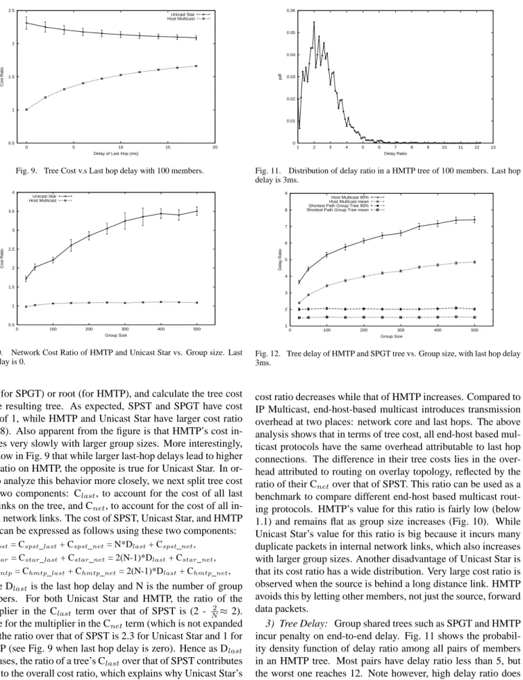
3) Tree Delay: Group shared trees such as SPGT and HMTP
incur penalty on end-to-end delay. Fig. 11 shows the probabil-ity densprobabil-ity function of delay ratio among all pairs of members in an HMTP tree. Most pairs have delay ratio less than 5, but the worst one reaches 12. Note however, high delay ratio does
1 1.5 2 2.5 3 3.5 4 4.5 5 0 100 200 300 400 500
Inflation of Group Diameter
Group Size Host Multicast
Shortest Path Group Tree
Fig. 13. Inflation of group diameter for HMTP and SPGT tree. Last hop delay is 3ms. 1 2 3 4 5 6 7 8 0 5 10 15 20 Delay Ratio
Delay of Last Hop (ms) Host Multicast 90%
Host Multicast mean Shortest Path Group Tree 90% Shortest Path Group Tree mean
Fig. 14. Tree delay of HMTP and SPGT tree vs. Last hop delay, with 100
members.
not necessarily mean large absolute delay. Large absolute de-lay is reflected in large group diameter inflation. Fig. 12 shows the average and 90%-tile delay ratio from our simulations as we increase the group size. The corresponding group diameter in-flation is shown in Fig. 13. As delay ratio increases in the former graph, the group diameter inflation stays largely flat in the latter graph. We again apply similar separation of delay overhead into network core component and last hop component. Fig. 14 shows overall tree delay ratio as we increase the last hop delays. Let Dnet be the delay from the source to a destination, excluding
both last hops. Then the delay of a single path can be expressed as:
Dunicast= Dunicast_last+ Dunicast_net= 2Dlast+ Dunicast_net,
Dspgt= Dspgt_last+ Dspgt_net= 2Dlast+ Dspgt_net,
Dhmtp= Dhmtp_last+ Dhmtp_net= (2 + 2H)*Dlast+ Dhmtp_net, where H is the number of intermediate end-hosts between the source and destination (on an end-host based multicast tree). The ratio over unicast of the first term is 1 for SPGT, and (1+H) for HMTP. The mean of the ratio over unicast of the second term is 1.7 for SPGT, and 2.3 for HMTP (see Fig. 14 when last hop de-lay is zero). As Dlastincreases, the first term contributes more
to the overall delay ratio. Hence SPGT’s delay ratio decreases towards 1. Since H is likely to be larger than 1.3, HMTP’s delay
1 2 3 4 5 6 0 100 200 300 400 500 Delay Ratio Group Size Host Multicast 90% Host Multicast mean Shortest Path Group Tree 90% Shortest Path Group Tree mean
Fig. 15. Network Delay Ratio vs. Group size. Last hop delay is 0.
1 2 4 8 16 32 64 128 256 1 2 4 8 16 32 64 128
Number of Physical Links
Physical Link Load
Unicast Star Host Multicast
Fig. 16. Link Load of a HMTP tree and Unicast Star, with 100 members.
ratio increases. Unlike the analysis for tree cost where the con-tribution of the first term depends only on last hop delay, the first term in the tree delay expression for HMTP depends also on the number of hops traversed, which is determined by the end-host multicast routing algorithm. This means that the delay overhead of HMTP cannot be attributed to the second term alone. Fig. 15 shows that delay ratios stay largely flat as we increase group size beyond 100 members when the last hop delay is zero. A more compact tree structure with smaller H will result in smaller delay ratio.
Increased tree cost and end-to-end delay over native multicast is expected for all end-host based multicast delivery trees. Delay results presented here include delays between all pairs of mem-bers in a multicast group. In reality, not all memmem-bers of a mul-ticast group will be senders. We expect that the limited number of active pairs and the use of host clustering due to hierarchical routing will allow HMTP to have a better delay ratio in practice.
4) Link Load: Fig. 16 compares the link load of HMTP and
Unicast Star in a multicast tree connecting a group with 100 members. Though most of the links have a load of 1, Unicast Star has very high load on a few links. The worst case happens at the last hop to the source, where the link load is almost the same as the group size, as expected. If one link is congested because of high link load, all the downstream members see
per-formance degradation. HMTP avoids this problem by reducing worst case link load significantly. Under HMTP, an end host can control the load on its last hop link by adjusting the number of neighbors it connects to. We use a maximum degree constraint of 8 throughout our simulations. In reality, the degree constraint can be adjusted according to available bandwidth. Smaller de-gree constraint results in a deeper tree, which may have a higher cost and higher delay, but with lower load on physical links.
5) Internet Experiment: In addition to simulations on
ran-dom topologies, we also run simulations on a snapshot of real Internet topology. To construct the Internet topology, we down-loaded one day’s (March 1st, 2001) worth of traceroute data from the NLANR site [12]. The traceroutes were conducted among every pair of more than 100 US sites. After removing incomplete measurements, we obtained a topology consisting of 978 routers and 96 hosts. We then ran 1000 simulations on this topology using the same parameters as the simulations we ran on the ran-domly generated topologies. Comparing the trees constructed by HMTP against that constructed by IP multicast3 we computed values for our various metrics, averaged over the 1000 runs. Our results are:
• tree cost ratio: 0.99, • mean delay ratio: 1.76, • 90%-tile delay ratio: 2.50,
• group diameter inflation: 2.40, and • worst link load: 8.
VIII. SUMMARY ANDFUTUREWORK
Deploying a new service on the Internet infrastructure is not a trivial task. The deployment path with least resistance is to go from network edges towards the core. WWW adoption serves as a successful model. It starts with no more than a simple client and a simple server, which any user can easily install and set up. As its usage increases, network operators are pushed by user demand to add core-level supports, such as web caching, into the network. We believe multicast delivery can follow a similar approach. Host Multicast implements multicast functionality at end hosts with explicit IP Multicast support and compatibility. It uses HMTP, a simple and scalable overlay multicast routing protocol to build shared distribution tree. In HMTP, each mem-ber only keeps state information about local neighbors and a few remote members. New members probe a small set of existing members to join the tree. The tree is self-organized and adapts to changes in network condition and group membership. It also has the ability to detect and break routing loops, and recover from network partition. Simulation results comparing HMTP’s performance against those of other protocols’ in various topolo-gies show that HMTP tree has low tree cost, moderately low delay, and low network link load.
One of our future work is to further improve the algorithm: reducing the worst-case delay ratio and introducing bandwidth
3
IP multicast does not create a minimum spanning tree, which explains the cost ratio below 1 in our result.
as a second routing metric. Another on-going work is to de-sign a solution for islands with multiple Dede-signated Members (DMs). Under our current architecture, when there are multi-ple group members in an island, incoming packets from other islands do not necessarily enter the island through the closest member, but rather take a detour via the DM. In a big island with group members scattered around, having a single DM serving as the only entrance/exit point may prohibit taking full advantage of IP Multicast deployment, and may give rise to a performance bottleneck. Therefore there is a need to dynamically elect mul-tiple DMs to serve an island. When there are mulmul-tiple DMs per island, they must coordinate with each other to prevent routing loops and packet duplications. We also plan to implement Host Multicast to support real-life applications.
REFERENCES
[1] Y. Chawathe, S. McCanne, and E. Brewer. “An architecture
for Internet content distribution as an infrastructure service”.
http://www.cs.berkeley.edu/˜ yatin/papers/scattercast.ps.
[2] Y. Chu, S. G. Rao, and H. Zhang. “A case for end system multicast”. In
Proc. of ACM SIGMETRICS, pages 1–12, June 2000.
[3] S. Deering and D. Cheriton. “Multicast routing in datagram internetworks and extended LANs”. ACM Transactions on Computer Systems, 8(2):85– 110, May 1990.
[4] R. Finlayson. “The UDP multicast tunneling protocol”. Internet Draft, IETF, March 2001.
[5] R. Finlayson, R. Perlman, and D. Rajwan. “Accelerating the deployment of multicast using automatic tunneling”. Internet Draft, IETF, February 2001.
[6] P. Francis. “Yoid: your own Internet distribution”.
http://www.isi.edu/div7/yoid/, March 2001.
[7] P. Francis, S. Jamin, C. Jin, Y. Jin, D. Raz, Y. Shavitt, and L. Zhang.
“IDMaps: A global Internet host distance estimation service”. In
ACM/IEEE Transactions on Networking, October 2001.
[8] M. Handley. “Session directories and scalable Internet multicast
ad-dress allocation”. ACM Computer Communication Review, 28(4):105–116, September 1998.
[9] D. Helder and S. Jamin. “End-host multicast communication using switch-trees protocols”. Global and Peer-to-Peer Computing on Large Scale
Dis-tributed Systems, 2002.
[10] H. Holbrook and B. Cain. “Source-specific multicast for IP”. Internet Draft, IETF, November 2000.
[11] P. Liefooghe. “CastGate: an auto-tunneling architecture for IP multicast”. Internet Draft, IETF, November 2001.
[12] National Laboratory of Applied Network Research, NSF Cooperative Agreement No. ANI-9807479. “NLANR active measurement project”. http://watt.nlanr.net/.
[13] P. Parnes, K. Synnes, and D. Schefström. “Lightweight application level multicast tunneling using mTunnel”. In Computer Communications, 1998. [14] D. Pendarakis, S. Shi, D. Verma, and M. Waldvogel. “ALMI: an application level multicast infrastructure”. In Proceedings of 3rd Usenix Symposium
on Internet Technologies and Systems (USITS 2001), March 2001.
[15] R. Perlman, C. Lee, T. Ballardie, J. Crowcroft, Z. Wang, T. Maufer, C. Diot, J. Thoo, and M. Green. “Simple Multicast: a design for simple, low-overhead multicast”. Internet Draft, IETF, March 1999.
[16] D. Thaler, M. Handley, and D. Estrin. “The Internet multicast address allocation architecture”. RFC 2908, IETF, September 2000.
[17] D. Thaler, M. Talwar, L. Vicisano, and D. Ooms. “IPv4 automatic multicast without explicit tunnels (AMT)”. Internet Draft, IETF, February 2001. [18] L. Wei and D. Estrin. “A comparison of multicast trees and algorithms”.
In Proc. of IEEE INFOCOM, June 1994.
[19] E. Zegura, K. Calvert, and S. Bhattacharjee. “How to model an internet-work”. In Proc. of IEEE INFOCOM, March 1996.