Robot Controller Control Unit RC700
RC700-A
Drive Unit RC700DU
RC700DU-A
Programming Software EPSON RC+7.0
Manipulator G1 G3 G6 G10 G20 series
RS series
C4 C8 series
Robot System
Safety and Installation
Read this manual firstS y s te m S af et y and I n s tal lat ion (R C 7 00 / EPSO N R C + 7 .0 ) R e v. 10
Safety and Installation (RC700 / EPSON RC+ 7.0) Rev.10 i
Robot System Safety and Installation
(RC700 / EPSON RC+7.0)
Rev.10
ii Safety and Installation (RC700 / EPSON RC+ 7.0) Rev.10
FOREWORD
Thank you for purchasing our robot products.
This manual contains the information necessary for the correct use of the Operator Panel.
Please carefully read this manual and other related manuals before installing the robot system.
Keep this manual handy for easy access at all times.
WARRANTY
The robot system and its optional parts are shipped to our customers only after being subjected to the strictest quality controls, tests, and inspections to certify its compliance with our high performance standards.
Product malfunctions resulting from normal handling or operation will be repaired free of charge during the normal warranty period. (Please ask your Regional Sales Office for warranty period information.)
However, customers will be charged for repairs in the following cases (even if they occur during the warranty period):
1. Damage or malfunction caused by improper use which is not described in the manual, or careless use.
2. Malfunctions caused by customers’ unauthorized disassembly. 3. Damage due to improper adjustments or unauthorized repair attempts. 4. Damage caused by natural disasters such as earthquake, flood, etc. Warnings, Cautions, Usage:
1. If the robot system associated equipment is used outside of the usage conditions and product specifications described in the manuals, this warranty is void.
2. If you do not follow the WARNINGS and CAUTIONS in this manual, we cannot be responsible for any malfunction or accident, even if the result is injury or death.
3. We cannot foresee all possible dangers and consequences. Therefore, this manual cannot warn the user of all possible hazards.
Safety and Installation (RC700 / EPSON RC+ 7.0) Rev.10 iii
TRADEMARKS
Microsoft, Windows, and Windows logo are either registered trademarks or trademarks of Microsoft Corporation in the United States and/or other countries. Other brand and product names are trademarks or registered trademarks of the respective holders.
TRADEMARK NOTATION IN THIS MANUAL
Microsoft® Windows® XP Operating system Microsoft® Windows® Vista Operating system Microsoft® Windows® 7 Operating system Microsoft® Windows® 8 Operating systemThroughout this manual, Windows XP, Windows Vista, Windows 7 and Windows 8 refer to above respective operating systems. In some cases, Windows refers generically to Windows XP, Windows Vista, Windows 7 and Windows 8.
NOTICE
No part of this manual may be copied or reproduced without authorization. The contents of this manual are subject to change without notice.
Please notify us if you should find any errors in this manual or if you have any comments regarding its contents.
INQUIRIES
Contact the following service center for robot repairs, inspections or adjustments. If service center information is not indicated below, please contact the supplier office for your region.
Please prepare the following items before you contact us. - Your controller model and its serial number - Your manipulator model and its serial number - Software and its version in your robot system - A description of the problem
iv Safety and Installation (RC700 / EPSON RC+ 7.0) Rev.10
SERVICE CENTER
MANUFACTURER
Seiko Epson Corporation
Toyoshina PlantRobotics Solutions Operations Division 6925 Toyoshina Tazawa, Azumino-shi, Nagano, 399-8285 Japan TEL : +81-(0)263-72-1530 FAX : +81-(0)263-72-1495
SUPPLIERS
North & South America
Epson America, Inc.
Factory Automation/Robotics 18300 Central Avenue Carson, CA 90746 USA TEL : +1-562-290-5900 FAX : +1-562-290-5999 E-MAIL : [email protected]
Europe
Epson Deutschland GmbH
Factory Automation Division Otto-Hahn-Str.4 D-40670 Meerbusch Germany
TEL
: +49-(0)-2159-538-1391FAX
: +49-(0)-2159-538-3170Safety and Installation (RC700 / EPSON RC+ 7.0) Rev.10 v
China
Epson (China) Co., Ltd.
Factory Automation Division
7F, Jinbao Building No. 89, Jinbao Street, Dongcheng District, Beijing,
China, 100005
TEL : +86-(0)-10-8522-1199 FAX : +86-(0)-10-8522-1120
Taiwan
Epson Taiwan Technology & Trading Ltd.
Factory Automation Division14F, No.7, Song Ren Road, Taipei 110, Taiwan, ROC
TEL : +886-(0)-2-8786-6688 FAX : +886-(0)-2-8786-6677
Korea
Epson Korea Co., Ltd.
Marketing Team (Robot Business) 27F DaeSung D-Polis A, 606
Seobusaet-gil, Geumcheon-gu, Seoul, 153-803 Korea
TEL : +82-(0)-2-3420-6692 FAX : +82-(0)-2-558-4271
Southeast Asia
Epson Singapore Pte. Ltd.
Factory Automation System 1 HarbourFront Place, #03-02, HarbourFront Tower One, Singapore 098633
TEL : +65-(0)-6586-5696 FAX : +65-(0)-6271-3182
vi Safety and Installation (RC700 / EPSON RC+ 7.0) Rev.10
India
Epson India Pvt. Ltd.
Sales & Marketing (Factory Automation) 12th Floor, The Millenia, Tower A, No. 1, Murphy Road, Ulsoor, Bangalore, India 560008
TEL : +91-80-3051-5000 FAX : +91-80-3051-5005
Japan
Epson Sales Japan Corporation
Factory Automation Systems Department Nishi-Shinjuku Mitsui Bldg.6-24-1
Nishishinjuku, Shinjuku-ku, Tokyo 160-8324 Japan
Safety and Installation (RC700 / EPSON RC+ 7.0) Rev.10 vii
For Customers in the European Union
The crossed out wheeled bin label that can be found on your product indicates that this product and incorporated batteries should not be disposed of via the normal household waste stream. To prevent possible harm to the environment or human health please separate this product and its batteries from other waste streams to ensure that it can be recycled in an environmentally sound manner. For more details on available collection facilities please contact your local government office or the retailer where you purchased this product. Use of the chemical symbols Pb, Cd or Hg indicates if these metals are used in the battery.
This information only applies to customers in the European Union, according to DIRECTIVE 2006/66/EC OF THE EUROPEAN PARLIAMENT AND OF THE COUNCIL OF 6 September 2006 on batteries and accumulators and waste batteries and accumulators and repealing Directive 91/157/EEC and legislation transposing and implementing it into the various national legal systems.
For other countries, please contact your local government to investigate the possibility of recycling your product.
The battery removal/replacement procedure is described in the following manuals: Controller manual / Manipulator manual(Maintenance section)
viii Safety and Installation (RC700 / EPSON RC+ 7.0) Rev.10
Before Reading This Manual
Concerning the security support for the network connection:
The network connecting function (Ethernet) on our products assumes the use in the local network such as the factory LAN network. Do not connect to the external network such as Internet.
In addition, please take security measure such as for the virus from the network connection by installing the antivirus software.
Security support for the USB memory:
Make sure the USB memory is not infected with virus when connecting to the Controller.
Control System Configuration
Robot Controller Drive Unit RC700DU is available for the following version. EPSON RC+ 7.0 Ver.7.1.0 or later
Robot Controller RC700-A
Robot Controller Drive Unit RC700DU-A is available for the following version. EPSON RC+ 7.0 Ver.7.1.2 or later
Manipulators can be connected with the following versions.
C4 series : EPSON RC+ 7.0 Ver.7.0.0
C8 series (C8XL) : EPSON RC+ 7.0 Ver.7.1.3
C8 series (C8, C8L) : EPSON RC+ 7.0 Ver.7.1.4 G1, G3, G6, G10, G20, RS series : EPSON RC+ 7.0 Ver.7.1.2
NOTESafety and Installation (RC700 / EPSON RC+ 7.0) Rev.10 ix
1. Safety
1
1.1 Conventions ··· 1
1.2 Design and Installation Safety ··· 2
1.2.1 Relevant Manuals ··· 2
1.2.2 Designing a Safe Robot System ··· 3
1.3 Operation Safety ··· 7
1.3.1 Safety-related Requirements ··· 9
1.3.2 Part Names / Arm Motion ··· 10
1.3.3 Operation Modes ··· 28
1.4 Maintenance Safety ··· 29
1.5 Emergency Stop ··· 32
1.5.1 Free running distance in emergency ··· 34
1.5.2 How to reset the emergency mode ··· 41
1.6 Labels ··· 42
1.6.1 Controller ··· 42
1.6.2 Manipulator ··· 44
1.7 Safety Features ··· 53
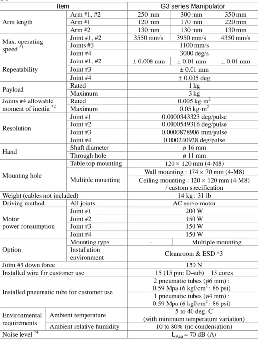
1.8 Manipulator Specifications ··· 56
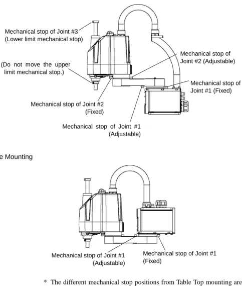
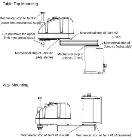
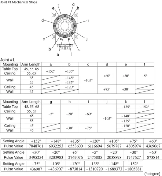
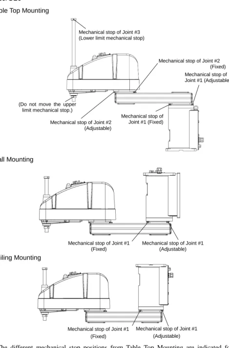
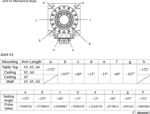
1.9 Motion Range Setting by Mechanical Stops ··· 94
1.10 End User Training ··· 111
2. Installation
112
System Example ··· 1132.1 Outline from Unpacking to Operation of Robot System ··· 115
2.2 Unpacking ··· 116 2.2.1 Unpacking Precautions ··· 116 2.3 Transportation ··· 117 2.3.1 Transportation Precautions ··· 117 2.3.2 Manipulator Transportation ··· 118 2.4 Manipulator Installation ··· 123 2.4.1 Installation Precautions ··· 123 2.4.2 Environment ··· 124 2.4.3 Noise level ··· 124 2.4.4 Base Table ··· 125 2.4.5 Installation Procedure ··· 127
2.5 Control unit and Drive unit Installation ··· 139
2.5.1 Installation Precautions ··· 139
2.5.2 Installation··· 140
2.5.3 Wall Mounting Option ··· 141
2.6 Connection to EMERGENCY Connector ··· 142
2.6.1 Safety Door Switch and Latch Release Switch ··· 142
2.6.2 Safety Door Switch ··· 143
2.6.3 Latch Release Switch ··· 143
2.6.4 Checking Latch Release Switch Operation ··· 144
2.6.5 Emergency Stop Switch ··· 145
2.6.6 Checking Emergency Stop Switch Operation ··· 145
2.6.7 Pin Assignments··· 147
x Safety and Installation (RC700 / EPSON RC+ 7.0) Rev.10
2.6.9 Circuit Diagrams – Drive unit ··· 150
2.7 Power supply / AC power cable ··· 154
2.7.1 Power Supply ··· 154
2.7.2 AC Power Cable ··· 155
2.8 Drive Unit Connection ··· 156
2.9 Drive Unit Setup ··· 157
2.10 Connecting Manipulator and Controller ··· 158
2.10.1 Connecting Precautions ··· 158
2.11 Power-on ··· 159
2.11.1 Power-on Precautions ··· 159
2.11.2 Power ON Procedure ··· 161
2.12 Saving Default Status ··· 161
2.13 Adding Information of the Additional System ··· 162
3. First Step
164
3.1 Installing EPSON RC+ 7.0 Software ··· 1643.2 Development PC and Controller Connection ··· 167
3.2.1 About Development PC Connection USB Port ··· 167
3.2.2 Precaution ··· 168
3.2.3 Software Setup and Connection Check ··· 168
3.2.4 Backup the initial condition of the Controller ··· 169
3.2.5 Disconnection of Development PC and Controller ··· 170
3.2.6 Moving the Robot to Initial Position ··· 170
3.3 Writing your first program ··· 176
4. Second Step
183
4.1 Connection with External Equipment ··· 1834.1.1 Remote Control··· 183
4.1.2 Ethernet ··· 183
4.1.3 RS-232C (Option)··· 183
4.2 Ethernet Connection of Development PC and Controller ··· 183
4.3 Connection of Teach Pendant (Option) ··· 184
5. General Maintenance
185
5.1 Maintenance ··· 1855.1.1 Manipulator ··· 185
5.1.2 Control Unit (RC700, RC700-A)··· 188
5.1.3 Drive Unit (RC700DU, RC700DU-A)··· 188
5.2 Overhaul ··· 189
5.3 Tightening Hexagon Socket Head Cap Bolts ··· 191
5.4 Greasing ··· 192
Safety and Installation (RC700 / EPSON RC+ 7.0) Rev.10 xi
6. Manuals
195
Software ··· 195 Software Options ··· 195 Controller ··· 196 Controller Options ··· 196 Manipulator ··· 196Safety and Installation (RC700 / EPSON RC+ 7.0) Rev.10 1
1. Safety
Installation and transportation of robots and robotic equipment shall be performed by qualified personnel and should conform to all national and local codes.
Please read this manual and other related manuals before installing the robot system or before connecting cables.
Keep this manual handy for easy access at all times.
1.1 Conventions
Important safety considerations are indicated throughout the manual by the following symbols. Be sure to read the descriptions shown with each symbol.
WARNING
This symbol indicates that a danger of possible serious injury or death exists if the associated instructions are not followed properly.
WARNING
This symbol indicates that a danger of possible harm to people caused by electric shock exists if the associated instructions are not followed properly.
CAUTION
This symbol indicates that a danger of possible harm to people or physical damage to equipment and facilities exists if the associated instructions are not followed properly.
2 Safety and Installation (RC700 / EPSON RC+ 7.0) Rev.10
1.2 Design and Installation Safety
Only trained personnel should design and install the robot system. Trained personnel are defined as those who have taken robot system training held by the manufacturer, dealer, or local representative company, or those who understand the manuals thoroughly and have the same knowledge and skill level as those who have completed the training courses.
To ensure safety, a safeguard must be installed for the robot system. For details on the safeguard, refer to the Installation and Design Precautions in the Safety chapter of the EPSON RC+ User’s Guide.
The following items are safety precautions for design personnel:
WARNING
■Personnel who design and/or construct the robot system with this product must read the Safety chapter in the EPSON RC+ User’s Guide to understand the safety requirements before designing and/or constructing the robot system. Designing and/or constructing the robot system without understanding the safety requirements is extremely hazardous, and may result in serious bodily injury and/or severe equipment damage to the robot system.
■The Manipulator and the Controller must be used within the
environmental conditions described in their respective manuals. This product has been designed and manufactured strictly for use in a normal indoor environment. Using the product in an environment that exceeds the specified environmental conditions may not only shorten the life cycle of the product but may also cause serious safety problems.
■The robot system must be used within the installation requirements described in the manuals. Using the robot system outside of the installation requirements may not only shorten the life cycle of the product but also cause serious safety problems.
Further precautions for installation are mentioned in the following manuals. Please read this chapter carefully to understand safe installation procedures before installing the robots and robotic equipment.
1.2.1 Relevant Manuals Refer
This manual : 2. Installation
Manipulator manual : Setup & Operation 3. Environment and Installation Controller manual : Setup & Operation 3. Installation
Safety and Installation (RC700 / EPSON RC+ 7.0) Rev.10 3 1.2.2 Designing a Safe Robot System
It is important to operate robots safely. It is also important for robot users to give careful consideration to the safety of the overall robot system design.
This section summarizes the minimum conditions that should be observed when using EPSON robots in your robot systems.
Please design and manufacture robot systems in accordance with the principles described in this and the following sections.
Environmental Conditions
Carefully observe the conditions for installing robots and robot systems that are listed in the “Environmental Conditions” tables included in the manuals for all equipment used in the system.
System Layout
When designing the layout for a robot system, carefully consider the possibility of error between robots and peripheral equipment. Emergency stops require particular attention, since a robot will stop after following a path that is different from its normal movement path. The layout design should provide enough margins for safety. Refer to the manuals for each robot, and ensure that the layout secures ample space for maintenance and inspection work.
When designing a robot system to restrict the area of motion of the robots, do so in accordance with the methods described in each manipulator manual. Utilize both software and mechanical stops as measures to restrict motion.
Install the emergency stop switch at a location near the operation unit for the robot system where the operator can easily press and hold it in an emergency.
Do not install the controller at a location where water or other liquids can leak inside the controller. In addition, never use liquids to clean the controller. Disabling Power to the System using lock out / tag out
The power connection for the robot controller should be such that it can be locked and tagged in the off position to prevent anyone from turning on power while someone else is in the safeguarded area.
4 Safety and Installation (RC700 / EPSON RC+ 7.0) Rev.10 End Effector Design
Provide wiring and piping that will prevent the robot end effector from releasing the object held (the work piece) when the robot system power is shut off.
Design the robot end effector such that its weight and moment of inertia do not exceed the allowable limits. Use of values that exceed the allowable limits can subject the robot to excessive loads. This will not only shorten the service life of the robot but can lead to unexpectedly dangerous situations due to additional external forces applied to the end effector and the work piece.
Design the size of the end effector with care, since the robot body and robot end effector can interfere with each other.
Peripheral Equipment Design
When designing equipment that removes and supplies parts and materials to the robot system, ensure that the design provides the operator with sufficient safety. If there is a need to remove and supply materials without stopping the robot, install a shuttle device or take other measures to ensure that the operator does not need to enter a potentially dangerous zone.
Ensure that an interruption to the power supply (power shutoff) of peripheral equipment does not lead to a dangerous situation. Take measures that not only prevent a work piece held from being released as mentioned in “End effector Design” but that also ensure peripheral equipment other than the robots can stop safely. Verify equipment safety to ensure that, when the power shuts off, the area is safe.
Remote Control
To prevent operation by remote control from being dangerous, start signals from the remote controller are allowed only when the control device is set to REMOTE, TEACH mode is OFF, and the system is configured to accept remote signals. Also when remote is valid, motion command execution and I/O output are available only from remote. For the safety of the overall system, however, safety measures are needed to eliminate the risks associated with the start-up and shutdown of peripheral equipment by remote control.
Emergency Stop
Each robot system needs equipment that will allow the operator to immediately stop the system’s operation. Install an emergency stop device that utilizes emergency stop input from the controller and all other equipment.
During an emergency stop, the power that is supplied to the motor driving the robot is shut off, and the robot is stopped by dynamic braking.
Safety and Installation (RC700 / EPSON RC+ 7.0) Rev.10 5 The emergency stop circuit should also remove power from all external components that must be turned off during an emergency. Do not assume that the robot controller will turn off all outputs if configured to. For example, if an I/O card is faulty, the controller cannot turn off a component connected to an output. The emergency stop on the controller is hardwired to remove motor power from the robot, but not external power supplies.
For details of the Safeguard system, refer to the following manuals. 1.5 Emergency Stop
Safeguard System
To ensure safety, a safeguard system should be installed for the robot system. When installing the safeguard system, strictly observe the following points: Refer to each manipulator manual, and install the safeguard system outside the maximum space. Carefully consider the size of the end effector and the work pieces to be held so that there will be no error between the moving parts and the safeguard system.
Manufacture the safeguard system to withstand calculated external forces (forces that will be added during operation and forces from the surrounding environment). When designing the safeguard system, make sure that it is free of sharp corners and projections, and that the safeguard system itself is not a hazard.
Make sure that the safeguard system can only be removed by using a tool.
There are several types of safeguard devices, including safety doors, safety barriers, light curtains, safety gates, and safety floor mats. Install the interlocking function in the safeguard device. The safeguard interlock must be installed so that the safeguard interlock is forced to work in case of a device failure or other unexpected accident. For example, when using a door with a switch as the interlock, do not rely on the switch’s own spring force to open the contact. The contact mechanism must open immediately in case of an accident.
Connect the interlock switch to the safeguard input of the drive unit’s EMERGENCY connector. The safeguard input informs the robot controller that an operator may be inside the safeguard area. When the safeguard input is activated, the robot stops immediately and enters pause status, as well as either operation-prohibited status or restricted status (low power status).
Make sure not to enter the safeguarded area except through the point where the safeguard interlock is installed.
6 Safety and Installation (RC700 / EPSON RC+ 7.0) Rev.10 The safeguard interlock must be installed so that it can maintain a safe condition until the interlock is released on purpose once it initiates. The latch-release input is provided for the EMERGENCY connector on the Controller to release the latch condition of the safeguard interlock. The latch release switch of the safeguard interlock must be installed outside of the safeguarded area and wired to the latch-release input.
It is dangerous to allow someone else to release the safeguard interlock by mistake while the operator is working inside the safeguarded area. To protect the operator working inside the safeguarded area, take measures to lock out and tag out the latch-release switch.
Presence Sensing Device
The above mentioned safeguard interlock is a type of presence sensing device, since it indicates the possibility of somebody being inside the safeguard system. When separately installing a presence sensing device, however, perform a satisfactory risk assessment and pay thorough attention to its dependability. Here are precautions that should be noted:
-Design the system so that when the presence sensing device is not activated or a dangerous situation still exists that no personnel can go inside the safeguard area or place their hands inside it.
-Design the presence sensing device so that regardless of the situation the system operates safely.
-If the robot stops operating when the presence sensing device is activated, it is necessary to ensure that it does not start again until the detected object has been removed. Make sure that the robot cannot automatically restart. Resetting the Safeguard
Ensure that the robot system can only be restarted through careful operation from outside the safeguarded system. The robot will never restart simply by resetting the safeguard interlock switch. Apply this concept to the interlock gates and presence sensing devices for the entire system.
Robot Operation Panel
The robot operation panel must not be located inside of the robot work envelope / workcell. Ensure that the robot system can be operated from outside of the safeguard.
Safety and Installation (RC700 / EPSON RC+ 7.0) Rev.10 7
1.3 Operation Safety
The following items are safety precautions for qualified Operator personnel:
WARNING
■ Please carefully read the Safety-related Requirements before operating the robot system. Operating the robot system without understanding the safety requirements is extremely hazardous and may result in serious bodily injury and/or severe equipment damage to the robot system.
■ Do not enter the operating area of the Manipulator while the power to the robot system is turned ON. Entering the operating area with the power ON is extremely hazardous and may cause serious safety problems as the Manipulator may move even if it seems to be stopped. ■ Before operating the robot system, make sure that no one is inside the safeguarded area. The robot system can be operated in the mode for teaching even when someone is inside the safeguarded area.
The motion of the Manipulator is always in restricted status (low speeds and low power) to secure the safety of an operator. However, operating the robot system while someone is inside the safeguarded area is extremely hazardous and may result in serious safety problems in case that the Manipulator moves unexpectedly.
■ Immediately press the Emergency Stop switch whenever the Manipulator moves abnormally while the robot system is operated. Continuing the operating the robot system while the Manipulator moves abnormally is extremely hazardous and may result in serious bodily injury and/or severe equipment change to the robot system.
WARNING
■To shut off power to the robot system, pull out the power plug from the power source. Be sure to connect the AC power cable to a power receptacle. DO NOT connect it directly to a factory power source. ■Before performing any replacement procedure, turn OFF the Controller
and related equipment, and then pull out the power plug from the power source. Performing any replacement procedure with the power ON is extremely hazardous and may result in electric shock and/or malfunction of the robot system.
8 Safety and Installation (RC700 / EPSON RC+ 7.0) Rev.10 WARNING
■ Do not insert or pull out the motor connectors while the power to the robot system is turned ON. Inserting or pulling out the motor connectors with the power ON is extremely hazardous and may result in serious bodily injury as the Manipulator may move abnormally, and also may result in electric shock and/or malfunction of the robot system.
CAUTION
■Whenever possible, only one person should operate the robot system. If it is necessary to operate the robot system with more than one person, ensure that all people involved communicate with each other as to what they are doing and take all necessary safety precautions. ■SCARA Robot:
Joint #1, #2, and #4:
If the joints are operated repeatedly with the operating angle less than 5 degrees, they may get damaged early because the bearings are likely to cause oil film shortage in such situation. To prevent early breakdown, move the joints larger than 50 degrees for about five to ten times a day.
Joint #3:
If the up-and-down motion of the hand is less than 10 mm, move the joint a half of the maximum stroke for five to ten times a day.
■ Vertical 6-axis Robot:
If the joints are operated repeatedly with the operating angle less than 5 degrees, they may get damaged early because the bearings are likely to cause oil film shortage in such situation. To prevent early breakdown, move the joints larger than 30 degrees for about five to ten times a day.
■ Oscillation (resonance) may occur continuously in low speed Manipulator motion (Speed: approx. 5 to 20%) depending on combination of Arm orientation and end effector load. Oscillation arises from natural oscillation frequency of the Arm and can be controlled by following measures.
Changing Manipulator speed Changing the teach points Changing the end effector load
Safety and Installation (RC700 / EPSON RC+ 7.0) Rev.10 9 1.3.1 Safety-related Requirements
Specific tolerances and operating conditions for safety are contained in the manuals for the robot, controller and other devices. Be sure to read those manuals as well.
For the installation and operation of the robot system, be sure to comply with the applicable local and national regulations.
Robot systems safety standards and other examples are given in this chapter. Therefore, to ensure that safety measures are complete, please refer to the other standards listed as well.
(Note: The following is only a partial list of the necessary safety standards.) EN ISO 10218-1 Robots and robotic devices -- Safety requirements for industrial
robots -- Part 1: Robots
EN ISO 10218-2 Robots and robotic devices -- Safety requirements for industrial robots -- Part 2: Robot systems and integration
ANSI/RIA R15.06 American National Standard for Industrial Robots and Robot Systems -- Safety Requirements
EN ISO 12100 Safety of machinery -- General principles for design -- Risk assessment and risk reduction
EN ISO 13849-1 Safety of machinery -- Safety-related parts of control systems -- Part 1: General principles for design
EN ISO 13850 Safety of machinery -- Emergency stop -- Principles for design EN ISO 13855 Safety of machinery -- Positioning of safeguards with respect to the
approach speeds of parts of the human body.
EN ISO 13857 Safety of machinery -- Safety distances to prevent hazard zones being reached by upper and lower limbs.
ISO 14120 EN 953
Safety of machinery -- Guards -- General requirements for the design and construction of fixed and movable guards
IEC 60204-1 EN 60204-1
Safety of machinery -- Electrical equipment of machines -- Part 1: General requirements
CISPR11 EN55011
Industrial, scientific and medical (ISM) radio-frequency equipment -- Electromagnetic disturbance characteristics -- Limits and methods of measurement
IEC 61000-6-2 EN 61000-6-2
Electromagnetic compatibility (EMC) -- Part 6-2: Generic standards -- Immunity for industrial environments
10 Safety and Installation (RC700 / EPSON RC+ 7.0) Rev.10 1.3.2 Part Names / Arm Motion
RC700 Left side (3) (4) (1) (2) (5) (6) (7) (8) (9) (10) (11) (12) (13) (14) (15) (16) (17) (18) (19)(20) (21) (22) (23) (24) RC700-A Left side (3) (4) (1) (2) (5) (6) (7) (8) (9) (10) (11) (12) (13) (14) (15) (16) (17) (18) (19)(20) (21) (22) (23) (24)
(1) Control unit Number label (2) MT label (3) LED (4) Seven-segment Display (5) M/C POWER connector (6) Fan Filter (7) Option slot (8) Battery (9) POWER switch (10) Connection Check label (11) EMERGENCY connector (12) TP port
(13) Standard RS-232C port
(14) Encoder Voltage Adjustment Switch (15) M/C SIGNAL connector
(16) R-I/O connector
(17) RC700: DU OUT connector RC700-A: OUT connector
(18) Development PC connection USB port (19) Memory port
(20) Trigger Switch
(21) LAN (Ethernet communication) port (22) I/O connector
(23) AC IN
Safety and Installation (RC700 / EPSON RC+ 7.0) Rev.10 11 RC700DU / RC700DU-A Left side (3) (4) (1) (2) (5) (6) (7) (8) (9) (10) (11) (12)(13) (14) (15) (16) (17)
(1) Drive Unit Number label (2) MT label
(3) LED
(4) M/C POWER connector (5) Fan Filter
(6) POWER switch (7) Connection Check label (8) EMERGENCY connector
(9) Encoder Voltage Adjustment Switch
(10) M/C SIGNAL connector (11) R-I/O connector
(12) RC700: DU OUT connector RC700-A: OUT connector (13) RC700: DU IN connector
RC700-A: IN connector (14) RC700DU No. setup switch (15) I/O connector
(16) AC IN
12 Safety and Installation (RC700 / EPSON RC+ 7.0) Rev.10
G1
The motion range of each arm is shown in the figure below. Take all necessary safety precautions.
Signal cable
Power cable
Fitting (black or blue)* for ø4 mm pneumatic tube User connector
(9-pin D-sub connector)
LED
MT label
(only for special order)
Face plate (Manipulator serial No.) CE label Joint #3
Brake release switch
Base Shaft
User connector (15-pin D-sub connector)
Fitting (black or blue)* for ø6 mm pneumatic tube Fittings (white)
for ø6 mm pneumatic tube
UR label Cable
User connector (9-pin D-sub connector) User connector
(15-pin D-sub connector)
Fittings (white) for ø6 mm pneumatic tube Fitting (black or blue)*
for ø6 mm pneumatic tube Fitting (black or blue)* for ø4 mm pneumatic tube
* Color differs depending on the shipment time Joint #2 (rotating) Joint #1 (rotating) Joint #3 (up/down) Joint #4 (rotating) Arm #1 Arm #2
Safety and Installation (RC700 / EPSON RC+ 7.0) Rev.10 13 When the system is placed in emergency mode, push the arm or joint of the Manipulator by hand as shown below:
Arm #1 Push the arm by hand. Arm #2 Push the arm by hand.
Joint #3 The joint cannot be moved up/down by hand until the electromagnetic brake applied to the joint has been released. Move the joint up/down while pressing the brake release switch. Joint #4 Rotate the shaft by hand.
When the brake release switch is pressed in emergency mode, the brake for Joint #3 is released. Be careful of the shaft while the brake release switch is pressed because the shaft may be lowered by the weight of an end effector.
14 Safety and Installation (RC700 / EPSON RC+ 7.0) Rev.10
G3
The motion range of each arm is shown in the figure below. Take all necessary safety precautions. CE label + − + − + − + − UR label Joint #3 Brake release switch
Joint #1 (rotating) Joint #2 (rotating) Joint #3 (up/down) Joint #4 (rotating) Arm #1 Arm #2 Base Shaft
MT label (only for special order) Face plate (Manipulator serial No.)
Signal cable
Power cable
Fitting (black or blue)* for ø4 mm pneumatic tube Fittings (black or blue)*
for ø6 mm pneumatic tube Fittings (white) for ø6 mm pneumatic tube User connector (15-pin D-sub connector) LED lamp
* Color differs depending on the shipment time
Safety and Installation (RC700 / EPSON RC+ 7.0) Rev.10 15 When the system is placed in emergency mode, push the arm or joint of the Manipulator by hand as shown below:
Arm #1 Push the arm by hand. Arm #2 Push the arm by hand.
Joint #3 The joint cannot be moved up/down by hand until the electromagnetic brake applied to the joint has been released. Move the joint up/down while pressing the brake release switch. Joint #4 Rotate the shaft by hand.
When the brake release switch is pressed in emergency mode, the brake for Joint #3 is released.
Be careful of the shaft while the brake release switch is pressed because the shaft may be lowered by the weight of an end effector.
16 Safety and Installation (RC700 / EPSON RC+ 7.0) Rev.10
G6
The motion range of each arm is shown in the figure below. Take all necessary safety precautions.
MT label
(only for custom specification) Signature label
(Serial No. of Manipulator)
Signal cable Power cable Fitting (black or blue)* for ø 6 mm pneumatic tube User connector
(15-pin D-sub connector) User connector
(9-pin D-sub connector)
CE label Joint #3 and #4
brake release switch
Joint #1 (rotating) Joint #2
(rotating)
Joint #3 (up and down)
Joint #4 (rotating) Arm #1 Arm #2 Base + − + − + − + − Shaft
Fitting (black or blue)* for ø 4 mm pneumatic tube Fitting (white)
for ø 6 mm pneumatic tube Fitting (white) for ø 4 mm pneumatic tube
LED lamp
UR label
Safety and Installation (RC700 / EPSON RC+ 7.0) Rev.10 17 When the system is placed in emergency mode, push the arm or joint of the Manipulator by hand as shown below:
Arm #1 Push the arm by hand. Arm #2 Push the arm by hand.
Joint #3 The joint cannot be moved up/down by hand until the electromagnetic brake applied to the joint has been released. Move the joint up/down while pressing the brake release switch. Joint #4 For G6-**1**,
Rotate the shaft by hand. For G6-**3**,
The shaft cannot be rotated by hand until the electromagnetic brake applied to the shaft has been released. Move the shaft while pressing the brake release switch.
The brake release switch affects both Joints #3 and #4. When the brake release switch is pressed in emergency mode, the brakes for both Joints #3 and #4 are released simultaneously.
(For G6-**1**, Joint #4 has no brake on it.)
Be careful of the shaft falling and rotating while the brake release switch is pressed because the shaft may be lowered by the weight of an end effector.
18 Safety and Installation (RC700 / EPSON RC+ 7.0) Rev.10
G10/G20
The motion range of each arm is shown in the figure below. Take all necessary safety precautions. + − + − + − + − Joint #3 and #4
brake release switch (rotating) Joint #1 Joint #2
(rotating)
Joint #3 (up and down)
Joint #4 (rotating) Arm #1 Arm #2 Base Shaft MT label
(only for custom specification) Signature label
(Serial No. of Manipulator)
Signal cable Power cable
Fitting (black or blue)* for ø 6 mm pneumatic tube
User connector (15-pin D-sub connector) User connector
(9-pin D-sub connector)
CE label
Fitting (black or blue)* for ø 4 mm pneumatic tube Fitting (white)
for ø 6 mm pneumatic tube
Fitting (white) for ø 4 mm pneumatic tube
LED lamp
UR label
Safety and Installation (RC700 / EPSON RC+ 7.0) Rev.10 19 When the system is placed in emergency mode, push the arm or joint of the Manipulator by hand as shown below:
Arm #1 Push the arm by hand. Arm #2 Push the arm by hand.
Joint #3 The joint cannot be moved up/down by hand until the electromagnetic brake applied to the joint has been released. Move the joint up/down while pressing the brake release switch. Joint #4 The shaft cannot be rotated by hand until the electromagnetic
brake applied to the shaft has been released.
Move the shaft while pressing the brake release switch.
The brake release switch affects both Joints #3 and #4. When the brake release switch is pressed in emergency mode, the brakes for both Joints #3 and #4 are released simultaneously.
Be careful of the shaft falling and rotating while the brake release switch is pressed because the shaft may be lowered by the weight of an end effector.
20 Safety and Installation (RC700 / EPSON RC+ 7.0) Rev.10
RS3
The motion range of each arm is shown in the figure below. Take all necessary safety precautions.
MT label (only for custom specification)
Signaturelabel
(Serial No. of Manipulator) Signal Cable Power Cable
User Connector (15-pin D-sub Connector)
CE label
Joint #3 and #4 brake release switch Joint #2
(rotating) Joint #1
(rotating)
Joint #3 (up and down)
Joint #4 (rotating) Arm #1 Arm #2 Base + − + − + − + − Shaft Base Arm #1 Arm #2
Power Cable Signal Cable
Fitting (white) for ø 6 mm pneumatic tube Fitting (white) for ø4 mm pneumatic tube Fitting (black or blue)*
for ø 6 mm pneumatic tube User Connector
(15-pin D-sub Connector)
Fitting (white) for ø 6 mm pneumatic tube
UR label Fitting (black or blue)*
for ø 6 mm pneumatic tube Fitting (white)
for ø4 mm pneumatic tube
Safety and Installation (RC700 / EPSON RC+ 7.0) Rev.10 21 When the system is placed in emergency mode, push the arm or joint of the Manipulator by hand as shown below:
Arm #1 Push the arm by hand. Arm #2 Push the arm by hand.
Joint #3 The joint cannot be moved up/down by hand until the electromagnetic brake applied to the joint has been released. Move the joint up/down while pressing the brake release switch. Joint #4 Rotate the shaft by hand.
Be careful of the shaft while the brake release switch is pressed because the shaft may be lowered by the weight of an end effector.
22 Safety and Installation (RC700 / EPSON RC+ 7.0) Rev.10
RS4
The motion range of each arm is shown in the figure below. Take all necessary safety precautions. Joint #2 (rotating) Joint #1 (rotating) Joint #4 (rotating) Arm #1 Arm #2 Base
+
−
+
−
+
−
+
−
Shaft Base Arm #1 Arm #2 LED lamp Signal Cable Power Cable User Connector (15-pin D-sub Connector)Fitting (white) for ø 6 mm pneumatic tube
Fitting (black or blue)* for ø 6 mm pneumatic tube Fitting (white)
for ø4 mm pneumatic tube
Signal Cable
Power Cable
Joint #3 (up and down)
User Connector (15-pin D-sub Connector)
Joint #3 and #4 brake release switch
Fitting (white) for ø 6 mm pneumatic tube Fitting (white) for ø4 mm pneumatic tube Fitting (black or blue)*
for ø 6 mm pneumatic tube Signaturelabel (Serial No. of Manipulator) CE label
* Color differs depending on the shipment time
Safety and Installation (RC700 / EPSON RC+ 7.0) Rev.10 23 When the system is placed in emergency mode, push the arm or joint of the Manipulator by hand as shown below:
Arm #1 Push the arm by hand. Arm #2 Push the arm by hand.
Joint #3 The joint cannot be moved up/down by hand until the electromagnetic brake applied to the joint has been released. Move the joint up/down while pressing the brake release switch. Joint #4 Rotate the shaft by hand.
Be careful of the shaft while the brake release switch is pressed because the shaft may be lowered by the weight of an end effector.
24 Safety and Installation (RC700 / EPSON RC+ 7.0) Rev.10
C4
The motion range of each arm is shown in the figure below. Take all necessary safety precautions. Joint #1 Base Arm #1 (Lower Arm) Arm #2 Arm #4 Joint #6 Joint #3 Joint #4 Joint #5 Arm #6 Joint #2 Arm #5 LED Lamp
This lamp lights up while the motors are ON. Upper Arm (Arms #3 to #6)
Joint Motion
Joint #1 : The whole Manipulator revolves. Joint #2 : The lower arm swings.
Joint #3 : The upper arm swings. Joint #4 : The wrist revolves. Joint #5 : The wrist swings. Joint #6 : The hand rotates.
Arm #3
When the LED lamp is lighting or the controller power is on, the current is being applied to the manipulator. (The LED lamp may not be seen depending on the Manipulator’s posture. Be very careful.) Performing any work with the power ON is extremely hazardous and it may result in electric shock and/or improper function of the robot system. Make sure to turn OFF the controller power before the maintenance work.
Safety and Installation (RC700 / EPSON RC+ 7.0) Rev.10 25 Signal cable Power cable
User cable connector (9-pin D-sub connector)
Fitting for ø 4 mm pneumatic tube
Standard-model / Clean-room model Cover Exhaust port
For ø8 mm pneumatic tube White
Blue
MT label (only for custom specification)
Signature label
(Serial No. of Manipulator)
CE label
(only for CE specification) UR label
26 Safety and Installation (RC700 / EPSON RC+ 7.0) Rev.10 C8
The motion range of each arm is shown in the figure below. Take all necessary safety precautions.
Joint #1 Base Arm #1 (Lower Arm) Arm #2 Arm #4 Joint #6 Joint #3 Joint #4 Joint #5 Arm #6 Joint #2 Arm #5 LED Lamp
This lamp lights up while the motors are ON. Upper Arm (Arms #3 to #6)
Arm #3 J1+ J1- J2- J2+ J3+ J3- J4- J4+ J5+ J5- J6- J6+ Joint Motion
Joint #1 : The whole Manipulator revolves. Joint #2 : The lower arm swings.
Joint #3 : The upper arm swings. Joint #4 : The wrist revolves. Joint #5 : The wrist swings. Joint #6 : The hand rotates.
(Figure: C8-A701* (C8))
When the LED lamp is lighting or the controller power is on, the current is being applied to the manipulator. (The LED lamp may not be seen depending on the Manipulator’s posture. Be very careful.) Performing any work with the power ON is extremely hazardous and it may result in electric shock and/or improper function of the robot system. Make sure to turn OFF the controller power before the maintenance work.
Safety and Installation (RC700 / EPSON RC+ 7.0) Rev.10 27
Cable backward model
Power cable Signal cable User cable connector (15-pin D-sub connector)
For ø6 mm pneumatic tubes Air1: white tube Air2: blue tube F-sensor cable connector Ethernet cable connector Standard-model : Cover Clean-room model : Exhaust port
For ø12 mm pneumatic tube
Cable downward model
Power cable Signal cable User cable connector
(15-pin D-sub connector)
For ø6 mm pneumatic tubes Air1: white tube Air2: blue tube F sensor cable connector Ethernet cable connector Standard-model : Cover Clean-room model : Exhaust port
For ø12 mm pneumatic tube
Cable backward model / Cable downward model
MT label (only for custom specification)
Signature label (Serial No. of Manipulator)
CE label (only for CE specification)
UR label (only for UL specification) KC/KCs label
Bolt hole M5 (for grounding)
28 Safety and Installation (RC700 / EPSON RC+ 7.0) Rev.10 1.3.3 Operation Modes
The robot system has three operation modes: TEACH, AUTO, and TEST modes.
TEACH mode
This mode enables point data teaching and checking close from the Robot using the Teach Pendant. Robot operates in Low power status.
AUTO mode This mode enables automatic operation (program execution) of the Robot system at the factory. In this mode, robot operation and program execution are not allowed when the safety door is open. TEST mode
(T1) This mode enables program verification while the Enable Switch is held down and the safeguard (including the safety door) is open.
This is a low speed program verification function (T1: manual deceleration mode) which is defined in Safety Standards.
In this mode, the specified Function can be executed with multi-task / single-task, multi-manipulator / single-manipulator at low speed.
(T2) RC700-A option TP3 only
This mode enables program verification while the Enable Switch is held down and the safeguard (including the safety door) is open.
Unlike the TEST/T1, the program verification in a high speed is available in this mode.
In this mode, the specified Function can be executed with multi-task / single-task, multi-manipulator / single-manipulator at high speed.
Safety and Installation (RC700 / EPSON RC+ 7.0) Rev.10 29
1.4 Maintenance Safety
Please read this section, Maintenance of the Manipulator manual, Maintenance of the Controller manual, and other related manuals carefully to understand safe maintenance procedures before performing any maintenance.
Only authorized personnel who have taken the safety training should be allowed to maintain the robot system. The safety training is the program for the industrial robot operator that follows the laws and regulations of each nation.
The personnel who have taken the safety training acquire knowledge of industrial robots (operations, teaching, etc.), knowledge of inspections, and knowledge of related rules/regulations. Only personnel who have completed the robot system-training and maintenance-training classes held by the manufacturer, dealer, or locally-incorporated company should be allowed to maintain the robot system.
WARNING
■ Do not remove any parts that are not covered in this manual. Follow the maintenance procedure strictly as described in this manual, Maintenance of the Manipulator manual, and Maintenance of the Controller manual. Improper removal of parts or improper
maintenance may not only cause improper function of the robot system but also serious safety problems.
■Keep away from the Manipulator while the power is ON if you have not taken the training courses. Do not enter the operating area while the power is ON. Entering the operating area with the power ON is extremely hazardous and may cause serious safety problems as the Manipulator may move even though it seems to be stopped.
■When you check the operation of the Manipulator after replacing parts, be sure to check it while you are outside of the safeguarded area. Checking the operation of the Manipulator while you are inside of the safeguarded area may cause serious safety problems as the Manipulator may move unexpectedly.
■Before operating the robot system, make sure that both the Emergency Stop switches and safeguard switches function properly. Operating the robot system when the switches do not function properly is extremely hazardous and may result in serious bodily injury and/or serious damage to the robot system as the switches cannot fulfill their intended functions in an emergency.
30 Safety and Installation (RC700 / EPSON RC+ 7.0) Rev.10 WARNING
■Be sure to connect the AC power cable to a power receptacle. DO NOT connect it directly to a factory power source. To shut off power to the robot system, pull out the power plug from the power source. Performing any work while connecting the AC power cable to a factory power source is extremely hazardous and may result in electric shock and/or malfunction of the robot system.
■Before performing any replacement procedure, turn OFF the Controller and related equipment, and then pull out the power plug from the power source.
Performing any replacement procedure with the power ON is extremely hazardous and may result in electric shock and/or malfunction of the robot system.
■ Be sure to connect the cables properly. Do not allow unnecessary strain on the cables. (Do not put heavy objects on the cables. Do not bend or pull the cables forcibly.) The unnecessary strain on the cables may result in damage to the cables, disconnection, and/or contact failure. Damaged cables, disconnection, or contact failure is extremely hazardous and may result in electric shock and/or improper function of the robot system.
CAUTION
■Carefully use alcohol, liquid gasket, and adhesive following respective instructions and also instructions below. Careless use of alcohol, liquid gasket, or adhesive may cause a fire and/or safety problems.
- Never put alcohol, liquid gasket, or adhesive close to fire. - Use alcohol, liquid gasket, or adhesive while ventilating the room. - Wear protective gear including a mask, protective goggles, and
oil-resistant gloves.
- If alcohol, liquid gasket, or adhesive gets on your skin, wash the area thoroughly with soap and water.
- If alcohol, liquid gasket, or adhesive gets into your eyes or mouth, flush your eyes or wash out your mouth with clean water thoroughly, and then see a doctor immediately.
Safety and Installation (RC700 / EPSON RC+ 7.0) Rev.10 31 CAUTION
■ Wear protective gear including a mask, protective goggles, and oil-resistant gloves during grease up. If grease gets into your eyes, mouth, or on your skin, follow the instructions below.
If grease gets into your eyes:
Flush them thoroughly with clean water, and then see a doctor immediately.
If grease gets into your mouth:
If swallowed, do not induce vomiting. See a doctor immediately. If grease just gets into your mouth, wash out your mouth with water thoroughly.
If grease gets on your skin:
32 Safety and Installation (RC700 / EPSON RC+ 7.0) Rev.10
1.5 Emergency Stop
If the Manipulator moves abnormally during operation, immediately press the Emergency Stop switch. Pressing the Emergency Stop switch immediately changes the manipulator to deceleration motion and stops it at the maximum deceleration speed.
However, avoid pressing the Emergency Stop switch unnecessarily while the Manipulator is running normally. Pressing the Emergency Stop switch locks the brake and it may cause wear on the friction plate of the brake, resulting in the short life of the brake.
Normal brake life cycle: About 2 years
(when the brakes are used 100 times/day)
To place the system in emergency mode during normal operation, press the Emergency Stop switch when the Manipulator is not moving.
Refer to the Controller manual for instructions on how to wire the Emergency Stop switch circuit.
Do not turn OFF the Controller while the Manipulator is operating.
If you attempt to stop the Manipulator in emergency situations, make sure to stop the Manipulator using the E-STOP of the Controller.
If the Manipulator is stopped by turning OFF the Controller while it is operating, following problems may occur.
Reduction of the life and damage of the reduction gear unit Position gap at the joints
In addition, if the Controller was forced to be turned OFF by blackouts and the like while the Manipulator is operating, make sure to check the following points after power restoration.
Whether or not the reduction gear is damaged Whether or not the joints are in their proper positions
If there is a position gap, perform calibration by referring to the Maintenance: Calibration in the Manipulator manual.
Manipulator manuals contain information on the Emergency Stop. Please also read the descriptions in the manuals and use the robot system properly.
Safety and Installation (RC700 / EPSON RC+ 7.0) Rev.10 33 Before using the Emergency Stop switch, be aware of the followings.
- The Emergency Stop (E-STOP) switch should be used to stop the Manipulator only in case of emergencies.
- To stop the Manipulator operating the program except in emergency, use Pause (halt) or STOP (program stop) commands
Pause and STOP commands do not turn OFF the motors. Therefore, the brake does not function.
- For the Safeguard system, do not use the circuit for E-STOP. For details of the Safeguard system, refer to the following manuals.
EPSON RC+ User’s Guide
2. Safety - Installation and Design Precautions - Safeguard System Safety and Installation
2.6 Connection to EMERGENCY Connector To check brake problems, refer to the following manuals. Manipulator Manual Maintenance
2.1.2 Inspection Point
- Inspection While the Power is ON (Manipulator is operating) Safety and Installation
5.1.1 Manipulator
34 Safety and Installation (RC700 / EPSON RC+ 7.0) Rev.10 1.5.1 Free running distance in emergency
The operating Manipulator cannot stop immediately after the Emergency Stop switch is pressed.
However, remember that the values vary depending on following conditions: Hand weight WEIGHT Setting ACCEL Setting Workpiece weight SPEED Setting Posture etc. Approximate time and distance of the free running are as follow:
G1
Conditions for measurement Accel setting 100 Speed setting 100 Load [kg] 1 Weight setting 1 Joint #1 Stop point Point where the
emergency stop signal is input Target point Start point of operation Joint #2 Controller RC700-A Manipulator G1-171*, G1-171*Z G1-221*, G1-221*Z Free running time
Joint #1 + Joint #2 [sec.] 0.17 0.18
Joint #3 [sec.] 0.13
Free running angle
Joint #1 [deg.] 22 28
Joint #2 [deg.] 19 20
Joint #1 + Joint #2 [deg.] 41 48
Free running
Safety and Installation (RC700 / EPSON RC+ 7.0) Rev.10 35
G3
Conditions for Measurement Accel Setting 100 Speed Setting 100 Load [kg] 3 Weight Setting 3
Joint #1 Point where the
emergency stop signal is input Start point of operation Target point Stop point Joint #2 Controller RC700-A Manipulator G3-25*** G3-30*** G3-35*** Free running time
Joint #1 + Joint #2 [sec.] 0.3 0.2 0.3
Joint #3 [sec.] 0.2 0.2 0.2
Free running angle
Joint #1 [deg.] 20 20 35
Joint #2 [deg.] 20 20 25
Joint #1 + Joint #2 [deg.] 40 40 60 Free running
36 Safety and Installation (RC700 / EPSON RC+ 7.0) Rev.10
G6
Conditions for Measurement Accel Setting 100 Speed Setting 100 Load [kg] 6 Weight Setting 6
Joint #1 Point where the
emergency stop signal is input Start point of operation Target point Stop point Joint #2 Controller RC700-A Manipulator G6-45*** G6-55*** G6-65*** Free running time
Joint #1 + Joint #2 [sec.] 0.5 0.5 0.5
Joint #3 [sec.] 0.4 0.4 0.4
Free running angle
Joint #1 [deg.] 35 30 35
Joint #2 [deg.] 70 55 70
Joint #1 + Joint #2 [deg.] 105 85 105 Free running
distance
Joint #3 G6-**1** [mm]
Safety and Installation (RC700 / EPSON RC+ 7.0) Rev.10 37
G10/G20
Conditions for Measurement
G10 G20 Accel Setting 100 100 Speed Setting 100 100 Load [kg] 10 20 Weight Setting 10 20 Joint #1 Start point of operation Target point Stop point Joint #2
Point where the emergency stop signal is input Controller RC700-A Manipulator G10-65*** G10-85*** G20-85*** G20-A0*** Free running time
Joint #1 + Joint #2 [sec.] 0.5 0.8 0.9 0.7
Joint #3 [sec.] 0.3 0.3 0.3 0.3
Free running angle
Joint #1 [deg.] 40 85 90 75
Joint #2 [deg.] 65 75 70 65
Joint #1 + Joint #2 [deg.] 105 160 160 140
Free running distance
Joint #3 G10/G20-**1** [mm]
38 Safety and Installation (RC700 / EPSON RC+ 7.0) Rev.10
RS
Conditions for Measurement
RS3-351* RS4-551* Accel Setting 100 Speed Setting 100 Load [kg] 3 4 Weight Setting 3 4 Joint #1 Point where the
emergency stop signal is input Start point of operation Target point Stop point Joint #2 Controller RC700-A Manipulator RS3-351* RS4-551* Free running time
Joint #1 + Joint #2 [sec.] 0.3 0.7
Joint #3 [sec.] 0.2 0.3
Free running angle
Joint #1 [deg.] 50 30
Joint #2 [deg.] 30 70
Joint #1 + Joint #2 [deg.] 80 100 Free running
Safety and Installation (RC700 / EPSON RC+ 7.0) Rev.10 39 C4 Conditions of Measurement C4 series ACCEL Setting 100 SPEED Setting 100 Load [kg] 4 WEIGHT Setting 4
Robot controller RC700 / RC700-A
Manipulator C4-A601** C4-A901**
Free running time [sec.] Arm #1 0.4 0.3 Arm #2 0.4 0.4 Arm #3 0.4 0.5 Arm #4 0.3 Arm #5 0.4 Arm #6 0.3 Free running angle [deg.] Arm #1 85 60 Arm #2 60 65 Arm #3 55 55 Arm #4 40 Arm #5 40 Arm #6 25
40 Safety and Installation (RC700 / EPSON RC+ 7.0) Rev.10 C8 Conditions of Measurement C8 series ACCEL Setting 100 SPEED Setting 100 Load [kg] 8 WEIGHT Setting 8
Robot controller RC700-A
Manipulator C8-A701** (C8) C8-A901** (C8L) C8-A1401** (C8XL)
Free running time [sec.] Arm #1 0.5 0.5 0.9 Arm #2 0.5 0.6 0.7 Arm #3 0.5 0.5 0.4 Arm #4 0.5 0.4 0.5 Arm #5 0.2 0.2 0.3 Arm #6 0.2 0.2 0.3 Free running angle [deg.] Arm #1 60 50 70 Arm #2 60 60 40 Arm #3 70 50 30 Arm #4 70 60 90 Arm #5 30 30 50 Arm #6 40 30 30
Safety and Installation (RC700 / EPSON RC+ 7.0) Rev.10 41 1.5.2 How to reset the emergency mode
Select EPSON RC+ [Tools] – [Robot Manager] – [Control Panel] tab, and then click <Reset>.
The Control Panel page contains buttons for basic robot operations, such as turning motors on/off and homing the robot. It also shows status for Emergency Stop, Safeguard, Motors, and Power.
42 Safety and Installation (RC700 / EPSON RC+ 7.0) Rev.10
1.6 Labels
Labels are attached around the locations of the Controller and Manipulator where specific dangers exist.
Be sure to comply with descriptions and warnings on the labels to operate and maintain the Robot System safely.
Do not tear, damage, or remove the labels. Use meticulous care when handling those parts or units to which the following labels are attached as well as the nearby areas:
1.6.1 Controller
Location Label Note
A
Residual voltage exists. To avoid electric shock, do not open the cover while the Power is ON, or for 300 seconds after the Power is OFF.
B
Disconnect and lockout main power before performing maintenance and repair.
C
Do not connect the followings to TP port. Connecting to the followings may result in malfunction of the device.
OPTIONAL DEVICE dummy plug, OP500, OP500RC, JP500, TP-3** series, and OP1
D
Hazardous voltage exists while the Manipulator is ON. To avoid electric shock, do not touch any internal electric parts.
Safety and Installation (RC700 / EPSON RC+ 7.0) Rev.10 43 RC700 / RC700-A Control Unit
C
D A
B
(Figure: RC700)
RC700DU / RC700DU-A Drive Unit
A D
44 Safety and Installation (RC700 / EPSON RC+ 7.0) Rev.10 1.6.2 Manipulator
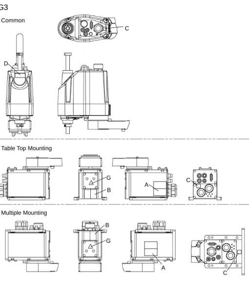
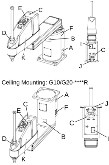
Location Label Note
A
Before loosening the base mounting screws, hold the arm and secure it tightly with a band to prevent hands or fingers from being caught in the Manipulator. For installation and transportation of robots, follow the directions in this manual.
B
Do not enter the operation area while the Manipulator is moving. The robot arm may collide against the operator. This is extremely hazardous and may result in serious safety problems.
C
Hazardous voltage exists while the Manipulator is ON. To avoid electric shock, do not touch any internal electric parts.
Safety and Installation (RC700 / EPSON RC+ 7.0) Rev.10 45
Location Label Note
D
You may get your hand or fingers caught between the shaft and cover when bringing your hand close to moving parts.
* Manipulators with bellows do not have this label for no danger of your hand or fingers being caught.
You may get your hand or fingers caught when bringing your hand close to moving parts.
E
C4: Be careful of the arm falling due to its own weight when pressing the brake release switch. This label is attached on the optional brake release box. C8: When releasing the brakes, be careful of the arm falling due to its own weight.
This label is attached on the Manipulator and optional brake release box.
Be careful of the hand falling while the brake release switch is being pressed.
F
Only authorized personnel should perform sling work and operate a crane and a forklift. When these operations are performed by unauthorized
personnel, it is extremely hazardous and may result in serious bodily injury and/or severe equipment damage to the robot system.
G HOT
46 Safety and Installation (RC700 / EPSON RC+ 7.0) Rev.10 Location of Labels
G1
B A C ESafety and Installation (RC700 / EPSON RC+ 7.0) Rev.10 47
G3
C D B A C B A C CommonTable Top Mounting
Multiple Mounting
G
48 Safety and Installation (RC700 / EPSON RC+ 7.0) Rev.10
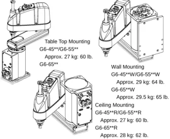
G6
A B D C C Table Top MountingG6-***S E B A C C D Ceiling Mounting G6-***SR E B A D C Wall Mounting G6-***SW E
Safety and Installation (RC700 / EPSON RC+ 7.0) Rev.10 49
G10/G20
Table Top Mounting: G10/G20-**** Wall Mounting: G10/G20-****W
D C C A B F I J E K B A D C E F J I K Ceiling Mounting: G10/G20-****R B A C C D E F J I K
50 Safety and Installation (RC700 / EPSON RC+ 7.0) Rev.10
RS
C D C C A C E B (Both sides) Bottom Side TopSafety and Installation (RC700 / EPSON RC+ 7.0) Rev.10 51
C4
C C C C C C A B Top View Back View Lateral View Front View52 Safety and Installation (RC700 / EPSON RC+ 7.0) Rev.10 C8
Top View
Back View
Lateral View Front View
C C C C C C A B C G
Cable Downward model Bottom View C Lateral View E F D C G
Safety and Installation (RC700 / EPSON RC+ 7.0) Rev.10 53
1.7 Safety Features
The robot control system supports safety features described below. However, the user is recommended to strictly follow the proper usage of the robot system by thoroughly reading the attached manuals before using the system. Failure to read and understand the proper usage of the safety functions is highly dangerous. Among the following safety features, the Emergency Stop Switch and Safety Door Input are particularly important. Make sure that these and other features function properly before operating the robot system.
For details, refer to the 2.5 Controller Installation - Safety Door Switch and Latch Release Switch.
Emergency Stop Switch
The EMERGENCY connector on the Controller has expansion Emergency Stop input terminals used for connecting the Emergency Stop switches.
Pressing any Emergency Stop switch can shut off the motor power immediately and the robot system will enter the Emergency Stop condition.
Safety Door Input
In order to activate this feature, make sure that the Safety Door Input switch is connected to the EMERGENCY connector at the Controller.
When the safety door is opened, normally the Manipulator immediately stops the current operation, and the status of Manipulator power is operation-prohibited until the safety door is closed and the latched condition is released. In order to execute the Manipulator operation while the safety door is open, you must change the mode selector key switch on the Teach Pendant to the “Teach” mode. Manipulator operation is available only when the enable switch is on. In this case, the Manipulator is operated in low power status.
Low Power Mode
The motor power is reduced in this mode.
Executing a power status change instruction will change to the restricted (low power) status regardless of conditions of the safety door or operation mode. The restricted (low power) status ensures the safety of the operator and reduces the possibility of peripheral equipment destruction or damage caused by careless operation.