Please cite this article as: M. Parvane, E. Rahimi, F. Jafarinejad, Optimization of Quantum Cellular Automata Circuits by Genetic Algorithm, International Journal of Engineering (IJE), IJE TRANSACTIONS B: Applications Vol. 33, No. 2, (February 2020) 229-236
International Journal of Engineering
J o u r n a l H o m e p a g e : w w w . i j e . i rOptimization of Quantum Cellular Automata Circuits by Genetic Algorithm
M. Parvanea, E. Rahimi*a, F. Jafarinejadb
a Faculty of Electrical & Robotic Engineering, Shahrood University of Technology
b Faculty of Computer Engineering, Shahrood University of Technology
P A P E R I N F O
Paper history: Received 21 October 2019
Received in revised form 10 January 2020 Accepted 17 Januray 2020
Keywords:
Quantum Cellular Automata Majority Logic Synthesis Genetic Algorithm Nanotechnology
A B S T R A C T
Quantum cellular automata (QCA) enables performing arithmetic and logic operations at the molecular scale. This nanotechnology promises high device density, low power consumption and high computational power. Unlike the CMOS technology where the ON and OFF states of the transistors represent binary information, in QCA, data is represented by the charge configuration. The primary and basic device in this paradigm is the three-input majority gate, thus in QCA, the conventional AND-OR mapping for implementation of logic functions is not effective. We introduce four primitive admissible geometric patterns, which aid in the identification of majority functions. For a non-majority function, a genetic algorithm (GA) is used to map the function to at most four non-majority gates in a wide range of implementations. We show that the emergence of specific genes will result in a further reduction in the number of majority gates in the network. The GA is intrinsically parallel and results in variety of implementations, which allows merging the layout and logic levels of the design and provides an important approach towards designing high-performance QCA circuits.
doi: 10.5829/ije.2020.33.02b.07
1. INTRODUCTION1
The CMOS technology, in the era of silicon, is approaching its limiting barriers of downscaling. Further miniaturization of CMOS devices is challenging due to quantum, short channel and several other effects [1, 2]. The demand for tiny size electronic devices, along with ultra-fast switching speed and ultra-low power dissipation has induced the driving force on the research for developing advanced nanoscale and molecular devices, which could be synthesized by inexpensive chemistry. The conventional CMOS technology utilizes transistors as electronic switches, where the ON and OFF states of the transistors represent binary information ‘1’ and ‘0’ respectively. The Boolean logic, functions of Boolean logic variables and Karnaugh maps (K-maps) were developed a few decades before the first transistor was fabricated in CMOS technology. The research in digital logic design and data structures fitted to CMOS technology has been
*Corresponding Author Email: [email protected]
(E. Rahimi)
(a)
(b)
(c)
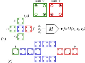
Figure 1. (a) Binary representation by charge configuration; (b) QCA majority gate (M) and its symbol; (c) QCA inverter gate (I)
The QCA logic has roots in the majority gates, majority data structures, and majority functions. The research in developing methods for implementation of majority functions and CAD tools for QCA is quite immature . The genetic algorithm (GA) approach in designing and optimization of conventional digital and analog circuits has been the subject of research in the last few decades [5,6]. The advantages of GAs over traditional algorithms are that they are intrinsically parallel, there is a high chance of getting an optimal solution, and a wide range of solutions is possible. In this paper, we review previous works on representation and implementation of majority functions and utilize a genetic algorithm to reduce the number of majority gates in implementation of any three-variable function. The remainder of this article is organized as follows. Section 2 presents QCA paradigm and corresponding logic gates in brief. We review the methods of recognizing majority functions and contribute a new approach based on geometric representation. A brief review of majority logic implementation and reduction methods based on the K-map, three-cube, and GA is given in section 3. Our proposed method, the two-level mapping based on GA, is presented in section 4. We describe and discuss the results in section 5. Finally, section 6 gives the conclusions.
2. THEORY
2. 1. QCA Paradigm In QCA, binary data is represented by the location of electric charges. The primary building block of QCA is a square cell with four quantum dots and two electrons, where each electron is localized in only one quantum dot [3]. Electrostatic repulsion forces between electrons and makes them be localized in antipodal quantum dots, resulting in two configurations, which represent the binary ‘0’ and ‘1’ (Figure 1a). By arranging the cells near each other, QCA devices are constructed. The
electrons cannot leave the cells, and the interactions between cells are electrostatic. The state of each cell is determined by calculation of the ground state energy, where the total forces are minimized. Figures 1b and 1c illustrate QCA majority gate (M) and inverter gate (I), respectively. The majority and the inverter gates provide a complete set of primitive devices to implement any Boolean function. The wire is used to transport binary data, and the majority gate performs the following logic operation on the three inputs x1, x2 and x3,
𝑓 = 𝑀(𝑥1, 𝑥2, 𝑥3) = 𝑥1𝑥2+ 𝑥2𝑥3+ 𝑥1𝑥3 (1)
The result of the majority function (M) is ‘1’ when at least two of the inputs are ‘1’. Moreover, the majority gate can perform the logic AND operation on the two of its inputs when the third input is set to ‘0’. Also, it can mimic the two-input OR gate when the third input is set to ‘1’. That is M(x1,x2,0)=x1x2, and M(x1,x2,1)=x1+x2. Conventionally, the inverter gate complements the input. Several circuits including the full adder [7], memory [8] and processor [9] have been implemented in QCA. Since majority gates can mimic the AND and OR gates, there is a possibility of using conventional AND-OR mapping based on the K-map method for implementation of Boolean functions in QCA; however, this method is naive. As an example, the AND-OR implementation of the function:
𝑓 = 𝑥1𝑥3+ 𝑥1𝑥2𝑥3+ 𝑥1𝑥2𝑥3+ 𝑥2𝑥3, (2)
requires six majority gates, which perform four AND and two OR operations. However, as we show in section 3, four majority gates can implement this function.
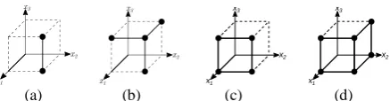
2. 2.Identification of Majority Logic Functions If a three-variable function is a majority function, it can be implemented by a single majority gate. Thus, as a primary step, the given function is examined to find out whether it is a majority function or not. There are several methods to find this out; including the algebraic, geometric, computational, and K-maps techniques [10]. The majority function is a specific type of threshold logic, and since every threshold logic is unate, the majority function is unate as well. Two useful representations of a logic function are the geometric and K-map [10]. In the geometric representation, the vertices of a hypercube are used. Since every variable function has eight states, vertices of a three-cube can be used to represent true or false states. By using the K-map representation, it can be shown that there are thirty-eight admissible patterns for the three-variable majority functions, where ten of them are positive [11]. Compared to K-map primitive patterns, we show that in three-cube representation, the number of primitive patterns is even less. There are only four patterns, which are illustrated in Figure 2. These
patterns are called the edge, corner, 1-face, and 2-face. The edge, corner, and 1-face patterns represent the
AND, majority (M), and OR operations,
respectively. The 2-face pattern consists of two faces of the cube, which have an intersection. This pattern represents a wire. For example, the functions
M(x1,0,x3)=x1x3, M(x1,x2,x̅3), M(1,x̅2,x3)= x̅2+x3, and
M(1,0,x̅3)= x̅3 correspond to edge, corner, 1-face and 2-face patterns, respectively. Since every cube has eight corners, twelve edges, six 1-faces and twelve 2-faces, a set of complete admissible majority patterns with thirty-eight elements can be designated with the primitive patterns in the geometric representation.
3. IMPLEMENTATION METHODS
There are generally two approaches to implement a three-variable function by majority gates, including the conventional algorithmic methods and heuristic methods based on the GA. These techniques are either based on the geometric, K-map, or algebraic representation.
3. 1.The Geometric and Algebraic Methods In order to synthesize a multi-output network with majority gates, the following procedure, which consists of some manual algebraic steps, can be applied [11]. First, each node Nj is decomposed into nodes, nj that have no more than three inputs. Node Nj is examined to find out whether it is a majority function. If it is a majority function, then the next node nj+1 is processed. Otherwise, nj is checked to determine whether two or three majority gates can implement it. If there is a common literal in all the product terms of nj, it is factored out. Then the AND-OR mapping is applied. As an example, in f =x1x̅2+x̅2x3 the term x̅2 is common and can be factored out as f =f1x̅2, where f1=x1+x3. Thus,
two majority gates are required. If there is no common literal, the node nj is checked to determine whether fewer than four AND-OR gates can implement it. Otherwise, finally, it is possible to implement it by four majority gates utilizing the K-map methods. The K-map methods are either manual [12] or automatic and algorithmic [11]. In a method based on the three-cube representation of functions, thirteen standard functions
have been recognized to form a standard table. The three-variable function is reduced to one of the standard functions utilizing a manual algebraic technique, and the majority logic implementation of the function can be found in the standard table [13] . The K-map based methods try to find three majority functions f1, f2 and f3 using the K-map of f in such a way that
𝑓 = 𝑀(𝑓1, 𝑓2, 𝑓3) = 𝑓1𝑓2+ 𝑓2𝑓3+ 𝑓1𝑓3. (4)
In the manual method, the K-map of three majority functions f1, f2 and f3 are constructed by application of the translation, rotation and mirror operations heuristically on the four primitive K-maps [12]. The automatic method uses an algorithm to find the K-map of the three majority gates f1, f2 and f3 [11].
More recent attention has focused on algebraic optimization methods [14-18], where representing and optimizing logic are carried out by using only the majority and inversion operations as basic operations. In these methods, logic functions are mapped into the majority-inverter graphs (MIGs), and exclusive Boolean algebra is applied. The points of a graph are accessed by primitive axioms, and with the aid of MIG algebraic algorithms, MIGs are optimized.
3. 2.Genetic Algorithm Methods The GA is a heuristic search method in an evolutionary set of probable solutions, which is called population. Each solution is encoded in a sequence of data, which is called chromosome. The chromosome consists of smaller units, where each unit is called a gene. The search starts in a primary random population, and a fitness value is assigned to each chromosome. The next generation of the population is formed by selecting some of the chromosomes with high fitness values from the previous population and creating new chromosomes. In order to generate a new chromosome, the crossover and mutation operators are applied to the old chromosomes. During the crossover process, some genes between two chromosomes are exchanged. A mutation is a random change in a gene of a chromosome. The GA has been used for the optimization of the number of gates in traditional combinational circuits in CMOS technology, where the AND, NOT, XOR and WIRE are the primitive gates [20]. The logic circuit is mapped to a network of gates, where each gate has two inputs and one output. The second input of each gate is connected to the output of a previous-level gate. The entire network is a chromosome, where each gene represents the gate type and the first input connection. In the case of QCA, a chromosome in the form of a MIG has been used to implement a three-input logic function and to minimize the number of majority functions [19]. The internal nodes can be the majority (M) and inverter (I) gates, while the external nodes (leaves) are variables or the
(a) (b) (c) (d) Figure 2.Four primitive admissible patterns in the geometric representation: (a) the edge pattern, (b) the corner pattern, (c) the 1-face pattern, (d) the 2-face pattern
x1
x2
x3
x1
x2
logic ‘1’. This chromosome has been altered later [21,22], to implement a two-output circuit. In most cases, the aim is to reduce the number of majority gates.
4. TWO-LEVEL MAPPING BASED ON GA
Any three-variable function f(x1,x2,x3) can be mapped to a two-level network of up to four majority gates. We use GA to find a number of chromosomes in the form of sets as Cm={gi,gj,gk} with three genes gi,gj, and gk, where
f=M(gi,gj,gk), and the order of genes is not important. Each gene encodes the K-map of an admissible majority function. We represent any three-variable K-map by a hexadecimal number, where the most and least significant nibble designates the first and second row of the K-map, respectively. As an example, the K-map of the majority function M(x1,x2,x3) and M(x1,x2,x̅3) is encoded as 27 and F6, respectively. The procedure of the GA is as follows. The initial population is formed by a random selection of n (the population size) genes from the set of forty patterns, which consists of thirty-eight admissible majority functions, the true gene (FF), and the false gene (00). The latter two genes aid in the reduction of the number of majority gates and possible implementation of f by two or three majority gates. The shapes of the thirty-eight admissible majority functions are the edge, corner, 1-face, and 2-face in the geometric representation. The majority operation is applied to the K-maps of the three genes gi,gj, and gk, in a cell-wise manner, and the result is stored in the form of a new K-map, r. If the K-map of r is the same as K-map of f, the correct chromosome has been found. The fitness function for the mth chromosome Fit(C
m) uses the
distance difference Dist(f,r) between the K-map of f and K-map of r, such that
𝐹𝑖𝑡(𝐶𝑚) = { 2,
if 𝐷𝑖𝑠𝑡(𝑓, 𝑟) = 0
1/𝐷𝑖𝑠𝑡(𝑓, 𝑟), 𝑜𝑡ℎ𝑒𝑟𝑤𝑖𝑠𝑒 , (5)
where, Dist(f,r) is defined as,
𝐷𝑖𝑠𝑡(𝑓, 𝑟) = ∑𝑖=7𝑖=0|𝑓𝑖− 𝑟𝑖|, (6)
and, ith element in the K-map of f and r is denoted by f i and ri, respectively. The fitness function gets values in the range [0.125,2], where 2 signifies the correct chromosome. The selection method is based on the roulette wheel algorithm, where the probability of selecting each chromosome is proportional to its fitness value and is given by
𝑃(𝐶𝑚) =
𝐹𝑖𝑡(𝐶𝑚)
∑𝑛𝑚=1𝐹𝑖𝑡(𝐶𝑚) (7)
The recombination process consists of single-point crossover, and the mutation is carried out in such a way that a selected gene is replaced with one of the thirty-eight admissible genes at random.
5. RESULTS AND DISCUSSIONS
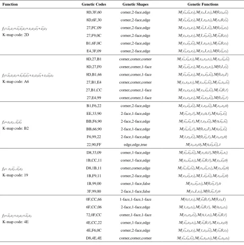
Five three-variable functions have been mapped to the two-level network of at most four majority gates utilizing the genetic algorithm described in the previous section. The GA results in a wide range of solutions for the problem. Only six correct chromosomes that implement each function are listed in Table 1. The genetic codes identify the chromosomes. The shape of each gene, which distinguishes its general function, is also listed in the table. The last column of the table shows the Boolean function of each gene. f1 can only be implemented by four majority gates. Two of the genes have 2-face and edge shapes, which mimic the OR and AND operation, respectively. Figure 3a shows the two-level implementation of f1 by four majority gates, where the three genes 8D, 3F, and 60 are used. The second function, f2, can be implemented in two ways: three corner genes or two corner genes and one 1-face gene that mimics a WIRE. The emergence of 1-face genes reduces the number of majority gates. Therefore, f2 can be implemented by three majority gates. Figure 3b illustrates implementation of f2 by the genes 8D, 3F, and 60. f3 can be implemented by four or three majority gates. The emergence of the true or 1-face gene in the case of f3 also reduces the number of majority gates to three gates (Figure 3c). Similarly, the false and 1-face genes reduce the number of gates to two gates in the implementation of f4. The last function, f5 is a majority function as the three 1-face genes identify it. Figure 4 depicts the layouts of the four functions f1, f2, f3, and f4, which were implemented by 195, 179, 114, and 41 quantum cells in QCA designer [8], respectively. In QCA, the layout is significantly correlated to timing [23] and power dissipation. We highlight that the reduction in the number of majority gates does not necessarily leads to optimization at the layout level and performance. Consequently, the procedure of circuit optimization should merge and correlate the layout and logic levels of the design. Essential considerations in floor-planning the QCA cells to increase the performance may include the number of complemented inputs, common inputs of the gates, wire lengths, wire crossings, cells that lie in the same clock zone, fixed or variable inputs, and spacing between wires.
TABLE 1. The GA implementation results
Function Genetic Codes Genetic Shapes Genetic Functions
f1=x̅1x3+x̅1x̅2x3+x1x2x̅3+x̅2x3
K-map code: 2D
8D,3F,60 corner,2-face,edge M(x̅1,x̅2,x3),M(x1,1,x3),M(0,x2,x̅3)
8D,6F,30 corner,2-face,edge M(x̅1,x̅2,x3),M(1,x2,x3),M(x1,0,x̅3)
27,FC,09 corner,2-face,edge M(x1,x2,x3),M(x̅1,1,x̅3),M(0,x̅2,x3)
27,F9,0C corner,2-face,edge M(x1,x2,x3),M(1,x̅2,x̅3),M(x̅1,0,x3)
B1,6F,0C corner,2-face,edge M(x1,x̅2,x̅3),M(1,x2,x3),M(x̅1,0,x3)
E4,3F,09 corner,2-face,edge M(x̅1,x2,x3),M(x1,1,x3),M(0,x̅2,x3)
f2=x̅1x2x3+x̅1x̅2x̅3+x1x2x̅3+x1x̅2x3
K-map code: A6
8D,27,B1 corner,corner,corner M(x̅1,x̅2,x3),M(x1,x2,x3),M(x1,x̅2,x̅3)
8D,27,F0 corner,corner,1-face M(x̅1,x̅2,x3),M(x1,x2,x3),M(0,1,x̅3)
8D,B1,66 corner,corner,1-face M(x̅1,x̅2,x3),M(x1,x̅2,x̅3),M(0,x2,1)
27,B1,E4 corner,corner,corner M(x1,x2,x3),M(x1,x2̅,x̅3),M(x̅1,x2,x̅3)
27,B1,CC corner,corner,1-face M(x1,x2,x3),M(x1,x̅2,x̅3),M(x̅1,0,1)
27,E4,99 corner,corner,1-face M(x1,x2,x3),M(x̅1,x2,x̅3),M(0,x̅2,1)
f3=x1x2+x̅2x̅3
K-map code: B2
B1,F6,22 corner,2-face,edge M(x1,x̅2,x̅3),M(1,x2,x̅3),M(x1,x2,0)
EE,33,90 2-face,1-face,edge M(x̅1,x2,1),M(x1,0,1),M(0,x̅2,x̅3)
BB,F6,90 2-face,2-face,edge M(x̅1,x̅2,1),M(1,x2,x̅3),M(0,x̅2,x̅3)
BB,66,90 2-face,1-face,edge M(x̅1,x̅2,1),M(0,x2,1),M(0,x̅2,x̅3)
F6,99,22 2-face,1-face,edge M(1,x2,x̅3),M(0,x̅2,1),M(x1,x2,0)
22,90,FF edge,edge,true M(x1,x2,0),M(0,x̅2,x̅3),1
f4= x1x̅2+x̅2x3
K-map code: 19
D8,33,09 corner,1-face,edge M(x̅1,x̅2,x̅3),M(x1,0,1),M(0,x̅2,x3)
1B,CC,11 corner,1-face,edge M(x1,x̅2,x3),M(x̅1,0,1),M(x1,x̅2,0)
D8,1B,11 corner,corner,edge M(x̅1,x̅2,x̅3),M(x1,x̅2,x3),M(x1,x̅2,0)
1B,F9,11 corner,2-face,edge M(x1,x̅2,x3),M(1,x̅2,x̅3),M(x1,x̅2,0)
1B,99,00 corner,1-face,false M(x1,x̅2,x3),M(0,x̅2,1),0
3F,99,00 2-face,1-face,false M(x1,1,x3),M(0,x̅2,1),0
f5=x̅1x2+x2x3+x̅1x3
K-map code: 4E
0F,CC,66 1-face,1-face,1-face M(0,1,x3),M(x̅1,0,1),M(0,x2,1)
6F,CC,06 2-face,1-face,edge M(1,x2,x3),M(x̅1,0,1), M(0,x2,x3)
72,0F,CC corner,1-face,1-face M(x1,x2,x̅3),M(0,1,x3),M(x̅1,0,1)
4E,CC,22 corner,1-face,edge M(x̅1,x2,x3),M(x̅1,0,1),M(x1,x2,0)
4E,F6,0C corner,2-face,edge M(x̅1,x2,x3),M(1,x2,x̅3),M(x̅1,0,x3)
D8,4E,4E corner,corner,corner M(x̅1,x̅2,x̅3),M(x̅1,x2,x3),M(x̅1,x2,x3)
(a) (b) (c) (d)
Figure 3. Logic level implementation of the four functions: (a) f1 with the genes 8D, 3F, and 60, (b) f2 with the genes 27, B1, and
(a) (b) (c) (d)
Figure 4.Layout level implementation of the four functions: (a) f1 with the genes 8D, 60, and 3F, (b) f2 with the genes B1, 27, and
CC, (c) f3 with the genes 90, 22, and FF, (d) f4 with the genes 99, 00, and 3F
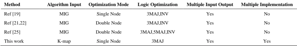
TABLE 2.Comparison of methods
Method Algorithm Input Optimization Mode Logic Optimization Multiple Input Output Multiple Implementation
Ref [19] MIG Single Node 3MAJ,INV Yes No
Ref [21,22] MIG Double Node 3MAJ,INV Yes No
Ref [25] MIG Double Node 3MAJ,5MAJ,INV Yes No
This work K-map Single Node 3MAJ Yes Yes
variable logic function [24]. They have focused on minimizing the number of inverter (INV) and majority (MAJ) gates as well. Roohi et al. [25] have used the same mehode on the MIGs consist of three-input and five-input MAJ gates. The input to their GA algorithms are MIGs and the optimization level is at two nodes. Logic functions should be mapped to MIGs before they can be processed. Mapping of functions to MIGs requires algorithms which were introduced a few years later by Ameru et al. [11,17]. Ameru et al. have also presented an algebraic optimization algorithm which maps Boolean functions to cost-effective pure MIGs. In our approach, any n-variable function is first decomposed into a network of nodes, where each node presents either a three-variable, two-variable, or one-variable function using the decomposition technique which was described in Section 3.1. Then each three variable-function node is optimized by the GA described in Section 3.2. We used the K-map of the logic function as the input to GA. Since the introduction of CMOS technology and the AND/OR operations, mapping of a logic function to a K-map is easily achieved. Our method optimizes only the number of MAJ gates, and the optimization is done at a single node. The GA optimization of a three-variable function based on only majority logic is significantly efficient and provides variety of implementations which allow us to merge them with the layout rules. Also, compared to the previous work [11], which uses a manual method to implement functions by two or three majority gates, the addition of the two genes, the true and false together with the 1-face gene enables automatic implementation of functions by three or two majority gates through the GA.
5. CONCLUSIONS
We introduced four admissible majority patterns in the geometric representation to aid in categorizing and designating majority functions. These patterns are the edge, corner, 1-face, and 2-face, which categorize the thirty-eight admissible majority functions into four groups. Functions with the edge, 2-face, and corner patterns perform AND, OR, and majority logic operations, respectively, while functions with the 1-face pattern represent wires. We added two other patterns, the true and the false, to make a complete set of forty patterns. We used a genetic algorithm to implement any three-variable function by at most four majority gates. The advantages of GA over conventional algorithms are that GAs are intrinsically parallel, so they are fast and give a wide range of solutions, which can be merged with layout rules to achieve a high-performance circuit since, in QCA, timing depends on the layout.
6. REFERENCES
1. H. Sasaki, M. Ono, T. Yoshitomi, T. Ohguro, S.-I. Nakamura, M. Saito, and H. Iwai, “1.5 nm direct-tunneling gate oxide si mosfet’s,” IEEE Transactions on Electron Devices , Vol. 43, No. 8, (1996), 1233-1242.
2. T. Nguyen and J. Plummer, “Physical mechanisms responsible for short channel effects in mos devices,”IEEE International
Electron Devices Meeting, Vol. 1, (1981), 596-599.
3. C. S. Lent, P. D. Tougaw, W. Porod, and G. H. Bernstein, “Quantum cellular automata,” Nanotechnology, Vol. 4, (1993), 49–57.
5. R. S. Zebulum, M. A. Pacheco, and M. M. B. Vellasco, Evolutionary electronics: automatic design of electronic circuits and systems by genetic algorithms. CRC press, 2001.
6. J. F. Miller, D. Job, and V. K. Vassilev, “Principles in the evolutionary design of digital circuits—part i,” Genetic
Programming and Evolvable Machines, Vol. 1, (2000), 7-35.
7. W. Wang, K. Walus, and G. A. Jullien, “Quantum-dot cellular automata adders,” 3rd IEEE Conference on Nanotechnology, Vol. 2, (2003), 461-464.
8. K.Walus,T.J.Dysart,G.A.Jullien,andR.A.Budiman,“Qcadesigner: a rapid design and simulation tool for quantum-dot cellular automata,” IEEE Trans. Nanotechnol., Vol. 3, (2004), 26-31.
9. K. Walus, M. Mazur, G. Schulhof, and G. A. Jullein, “Simple 4- bit processor based on quantum-dot cellular automata (qca),” IEEE International Conference on Application-Specific Systems, Architecture Processors, Vol. 1, (2005), 288-293.
10. Z. Kohavi and N. K. Jha, Switching and finite automata theory. Cam- bridge University Press, 2009.
11. R. Zhang, P. Gupta, and N. K. Jha, “Majority and minority network synthesis with application to qca-, set-, and tpl-based nanotechnologies,” IEEE Computer-Aided Design of
Integrated Circuits and Systems, Vol. 26, No. 7, (2007),
1233-1245.
12. K. Walus, G. Schulhof, G. Jullien, R. Zhang, and W. Wang, “Circuit de- sign based on majority gates for applications with quantum-dot cellular automata,” Asilomar Conference on Signals, Systems and Computers, Vol. 2, (2004), 1354-1357.
13. R. Zhang, K. Walus, W. Wang, and G. A. Jullien, “A method of majority logic reduction for quantum cellular automata,” IEEE
Transaction Nanotechnol., Vol. 3, No. 4, (2004), 443-450.
14.
L.Amaru,P.-E.Gaillardon,andG.DeMicheli,“Majority-invertergraph: A new paradigm for logic optimization,” IEEE
Computer-Aided Design of Integrated Circuits and Systems,
Vol. 35, No. 5, (2015), 806-819.
15. M. Soeken, L. G. Amaru`, P.-E. Gaillardon, and G. De Micheli, “Exact synthesis of majority-inverter graphs and its applications,” IEEE Computer-Aided Design of Integrated
Circuits and Systems, Vol. 36, No. 11, (2017), 1842-1855.
16. L. Amaru, P.-E. Gaillardon, A. Chattopadhyay, and G. De Micheli, “A sound and complete axiomatization of majority-n logic,” IEEE Transactions Nanotechnology, Vol. 65, No. 9, (2015), 2889-2895.
17. E. Testa, M. Soeken, L. G. Amaru`, W. Haaswijk, and G. De Micheli, “Mapping monotone boolean functions into majority,”
IEEE Transactions Computers, Vol. 68, No. 5, (2018),
791-797.
18. H. Riener, E. Testa, L. Amaru, M. Soeken, and G. De Micheli, “Size optimization of migs with an application to qca and stmg technologies,” in Proceedings of the 14th IEEE/ACM International Symposium on Nanoscale Architectures. ACM, (2018), 157-162.
19. M. Bonyadi, S. Azghadi, N. Rad, K. Navi, and E. Afjei, “Logic opti- mization for majority gate-based nanoelectronic circuits based on genetic algorithm,” International Conference on Electrical Engineering, (2007), 1-5.
20. C. C. Coello, A. D. Christiansen, and A. H. Aguirre, “Automated design of combinational logic circuits by genetic algorithm,”
Artificial Neural Nets and Genetic Algorithms, (1998),
333-336.
21. M. Houshmand, S. H. Khayat, and R. Rezaei, “Genetic algorithm based logic optimization for multi-output majority gate-based nano-electronic circuits,” IEEE International Conference on Intelligent Computing and Intelligent Systems, Vol. 1, (2009), 584-588.
22. R. Rezaee, M. Houshmand, and M. Houshmand, “Multi-objective opti- mization of qca circuits with multiple outputs using genetic program- ming,” Genetic Programming and
Evolvable Machines, Vol. 14, No. 1, (2013), 95-118,.
23. M. T. Niemier and P. M. Kogge, “Problems in designing with qcas: Layout= timing,” International Journal of Circuit Theory
and Applications, Vol. 29, No. 1, (2001), 49-62.
Optimization of Quantum Cellular Automata Circuits by Genetic Algorithm
M. Parvanea, E. Rahimia, F. Jafarinejadb
a Faculty of Electrical & Robotic Engineering, Shahrood University of Technology
b Faculty of Computer Engineering, Shahrood University of Technology
P A P E R I N F O
Paper history: Received 21 October 2019
Received in revised form 10 January 2020 Accepted 17 Januray 2020
Keywords:
Quantum Cellular Automata Majority Logic Synthesis Genetic Algorithm Nanotechnology
هدیکچ
نف یموتناوک یلولس یاتاموتا یروآ ماجنا ناکما
یم مهارف یلوکلوم حطس رد ار یقطنم و یتابساحم تایلمع نیا .دروآ
نف نف نیا .دراد یتابساحم یلااب تردق و دایز هشارت مکارت و مک ناوت فرصم یروآ یس فلاخ رب یروآ
نشور زا هک سام
یم هدافتسا روتسیزنارت ندوب شوماخ و یم هرهب تاعلاطا شیامن یارب یکیرتکلا راب شیارآ زا ،دوش
هس یقطنم هزاورد .درب
تیرثکا یدورو یلصا
نف نیا یقطنم هزاورد نیرت نیربانب .تسا یروآ
هدایپ لوادتم شور ساسا رب یقظنم یاهرادم یزاس
AND-OR
یفرعم تیرثکا عباوت صیخشت یارب دیدج یسدنه یوگلا راهچ هلاقم نیا رد .تسین رثوم یم
هدایپ یارب .مینک
اب عباوت ریاس یزاس هزاورد
هدرک هدافتسا کیتنژ متیروگلا زا تیرثکا یاه عباوت طسوت ار هاوخلد عبات ره هک یروط هب میا
هدایپ حطس ود رد یدورو هس تیرثکا یم یزاس
.دنک یم ناشن نژ روهظ میهد هداس ثعاب صاخ یاه
رادم رتشیب یزاس
یم .دوش تیزم تیروگلا باوج دادعت اب هارمه هک تسا نآ ندوب یزاوم لیلد هب نآ یلااب تعرس کیتنژ م ناکما دایز یاه
یم ار رادم ییامناج هنیهب یحارط د
ه د .