Volume 13, Number 2, pp. 173–186. http://www.scpe.org c 2012 SCPE
DYNAMIC DISTRIBUTED PROGRAMS CONTROL BASED ON GLOBAL PROGRAM STATES MONITORING
J. BORKOWSKI†AND M. TUDRUJ† ‡
Abstract. The paper concerns designing distributed program execution control based on global application states monitoring in the presence of a dynamic number of processes and threads. Global program execution control is based on application states monitoring at the level of processes/threads in clusters of multi–core processors. A special control infrastructure is proposed based on synchronizers, which collect state information from processes and threads, detect strongly consistent application global states, evaluate control predicates and send respective control signals. An algorithm for detection of strongly consistent global states for a variable number of processes/threads is presented.
1. Introduction. Writing distributed programs with complicated global control structures for execution in clusters of processors is easier when some support for automatic monitoring and handling of global application states is provided in the run time system. Commercial distributed systems do yet not support this idea. Hence, the program execution control based on the monitoring of global application states has to be programmed by programmers from scratch. It requires tedious programming of the collection of constituent local states and designing out of them global states which had happened in parallel in distributed processes of an application. Programming these aspects of program execution control is complicated and takes much of programmer’s time. Besides it is error prone. This paper relates to an original distributed program design framework PEGASUS (Program Execution Governed by Asynchronous SUpervision of States) [6, 24], which assumes a built in support for handling the local and global application states and automated design of program execution control based on global states monitoring.
Some introductory research results on the use of the global application states monitoring in the design of execution control of distributed programs can be found in literature. Linda environment [1] provides a common global tupple space for the exchange of global control information and supports primitives for writing and reading in it. Some solutions leading to the design of global control for interactive software components can be found in coordination languages. Manifold and Reo environments [2] have ben provided with primitives for inclusion of communicating software components into coordinated structures. Nevertheless, no notion of a global state has been used in these systems. Global application states were basic concepts in the Meta system [3], which enabled designing distributed programs based on communicating components. In the Meta system, application processes were able to send messages on their local states on which consistent global states were generated and the respective global predicates were evaluated. In Meta, complicated formalism based on guards was used to express control based on global states. An attempt to simplify this formalism was undertaken in the Lomita language [3]. But it suffered of inefficiency due to very costly ordered state message broadcasts. Global control constructs for the OCCAM language were proposed in [4] with an implementation based on replication of global state variables. The first infrastructure for the run–time supported design of the asynchronous global execution control of distributed programs in C language based on monitoring of global application states was implemented in a graphical parallel program design system PS–GRADE [5].
The features of the PS–GRADE and other distributed program design frameworks [9] have been substan-tially extended in PEGASUS. The main extension are the graphically supported global high level control flow constructs in which the flow of control at the level of the distributed program components depends on the pred-icates computed on global application states. In this respect, the PS–GRADE did not provide any mechanisms for structural control flow steering by global application states while taking care of the asynchronous control of the internal process behaviour. Another important extension is the global program execution control exercised at the thread level, important for the evolved software design for multicore processors. One more extension is the separation of the communication frameworks for maintaining the control data from the communication environment for computational data. This separation is on one hand logical and on the other hand physical since separate networks are assumed. Such logical and hardware support strongly improves control design efficiency as has been already discovered by simulation experiments for PS–GRADE [21].
Current implementation of the PEGASUS framework assumes that the number of processes and threads
†Polish–Japanese Institute of Information Technology, 86 Koszykowa Str., 02–008 Warsaw, Poland ([email protected]) ‡Institute of Computer Science, Polish Academy of Sciences, Jana Kazimierza 5, 01–248 Warsaw, Poland
whose local states contribute to the definition of the program global consistent states, is known at the application program compile time. In the research reported in this paper, the number of threads and processes taken into account is assumed to be variable and is set dynamically at program run time. The variable number of processes has been considered in [7, 8, 9, 10, 11], however only for the group data communication control. With the new assumptions, in the dynamic distributed programs designed under the PEGASUS framework, the automatically constructed global states based on local states of a variable number of threads or processes define the control flow and the functional features of programs. These features extend the functionality of the PEGASUS framework towards more flexible control constructs, however at the price of new algorithms for the construction of strongly consistent global states and more specific methods for state messages sending and signal reception in application program components. Both these problems are presented and discussed in this paper.
A short presentation of this research has been published in [25]. The present paper adds many details and includes the following relevant material:
• dynamic SCGS detection algorithm described in detail with a pseudo–code,
• an application example,
• a description of the PEGASUS system as an example of an environment where the dynamic SCGS detection can be applied.
The paper consists of six parts. In the first part, the application program execution control based on global states monitoring is explained. The second part, presents the related research on the dynamic process membership in program control. The third part presents the algorithm for the detection of global application states in the presence of a variable number of processes/threads. The fourth part shortly describes the graphical design of application programs in the PEGASUS framework. The fifth part discusses global program execution control based on dynamic process groups. The sixth part outlines a relevant example with a variable number of processes.
2. Global states monitoring for application control. An analysis of existing parallel application control methods e.g. [12, 13, 14], has motivated us to have a global view of a running distributed application state used when defining distributed program execution control. Such control should be based on global program execution control high–level primitives. To increase the program code clarity, the code sections responsible for program execution control should be separated from the code sections responsible for computations. To increase the distributed program performance, the synchronization and communication of the control data and steering orders should be implemented without passive waiting.
signal
cancelled activity
signal
saved time
Fig. 2.1: Code activation (left) and cancellation (right) by control signals
synchronized with a known accuracy [16]. The SCGSs based on such local state messages can be constructed in O(E NlogN) time, where N is the number of processes and E is the number of events per process. The complexity of the algorithm with real–time event timestamps is lower than that of the algorithms, which use logical vector clocks since the later leads to SCGS detection with the exponential complexity. By using networks of parallel synchronizers, a distributed hierarchical SCGS detection can be organized, which is speeding up the SCGS detection for complicated state cases [17].
An SCGS is a state, which has occurred for sure in all involved processes, in difference to potential global states obtained with the use of logical clocks. Timestamps defined with a known accuracy requires a processor clocks synchronization facilities installed in the executive distributed system.
The clock synchronization needed here can be obtained in many ways, depending on the assumed accuracy and budget. The least costly and the cheapest is the Network Time Protocol which can reduce the clock skew to tens ofµs. The more costly is the Precision Time Protocol, which supported by a dedicated time messages transmission network can provide the clock skew below 1µs.
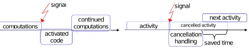
Control predicates used for definition of process execution control represent control conditions, which are checked when a given global state is reached. The predicates are encapsulated in synchronizers as specially structured pieces of code, which are defined by a programmer as parts of the application. The predicates can be defined based on SCGSs (global or regional) or observed states. For SCGSs, the predicates are checked on each detected SCGS state. If a predicate is fulfilled, the Unix–type control signals are sent to selected processes. The signals can activate designated code sections in target processes immediately upon their arrival, suspending current computations. Alternatively, they can cancel current computations, making processes to proceed immediately to further parts of their algorithms, see Fig. 2.1.
If the signals are sent between a synchronizer and processes located on different processors, the signals are transformed into control messages when they leave the processor of the synchronizer. The messages are sent by the use of a message passing library. The messages are asynchronously received at the target process processor and then transformed into classic Unix signals which are delivered asynchronously. With the use of asynchronous control signals, a process does not need to stop and wait passively for control orders sent by synchronizers.
In PS–GRADE, the set of parallel application processes taken into account for the monitoring of global application states was defined statically by a programmer. This limitation can be removed in the new enhanced PEGASUS system. Under PEGASUS, each process usually contains many parallel threads which can be moni-tored and controlled by synchronizers through global predicates, in a similar way as processes [17]. It is a quite common programming practice to create and destroy the threads when necessary. Therefore, the global control system should enable to deal with dynamically changing set of monitored entities (threads or processes). In this paper, we examine methods for monitoring global states of dynamically changing sets of threads/processes and methods for organizing the respective application control.
3. Related research. The problem of cooperation between processes in a group when the processes can join and leave the group has been analyzed in the literature. Several authors studied such cooperation using broadcast as the main communication primitive.
A good insight to the problem in presented in [7] and [8]. There, the notion of views was defined. A view stands for an interval when the group membership is constant. In a single view classic (static) algorithms can be used to implement broadcasts. The difficulty has been moved largely to view maintenance — creation of new views and installation of new views in processes. A similar approach has been taken in the Totem system [9]. A dedicated service was created there to monitor and maintain the membership.
logically (before/after) ignoring actual (wall clock) time relations. The real time is used only to detect dormant members, e.g. as in [20], where assumptions on maximal token transfer time exist.
Our case differs from the cases analyzed in the literature in a few important aspects.
• The communication we need is of many–to–one type (processes reporting to a synchronizer) and one–to– many type (a synchronizer sending control signals to processes). It is not many–to–many communication — processes do not need to know about each other.
• We use Strongly Consistent Global States and real–time timestamps. This makes the coordination between processes much different than in the case of logical time.
• The control mechanism in our system is based on consistent global state monitoring — we must be able to construct consistent global states with changing process membership.
• The emphasis in our system is not on communication (sending messages with data), but on control (sending commands and states). The impact of membership changes should be analyzed from another point of view.
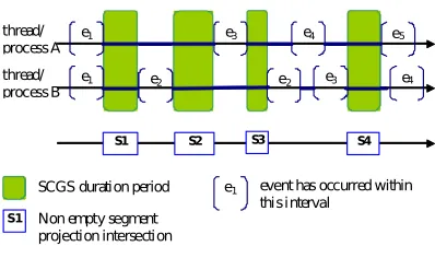
4. SCGS detection. The Strongly Consistent Global States (SCGS) were introduced in [19]. They are analogous to the Consistent Global States (CGS) as defined in e.g. [18]. A CGS is a set of local process states, one state from each process, with the property that the states are pairwise concurrent. The concurrency is defined with the happened–before relation and logical vector clocks can trace it. In SCGS the state concurrency is defined with the help of real–time (wall clock) timestamps. To be able to use real time clock the processes must have access to a global shared clock or their local clocks must be synchronized. It is assumed that the clocks used by the processes are not ideally synchronous and that the upper bound of the clock skew is known. In such a situation, an event can be depicted on a time axis as an interval rather than a point. An event occurs momentarily of course, but we are able to pinpoint the time of its occurrence due to not perfect clock synchronization. Instead, we determine an interval within which we know the event has occurred. Fig. 4.1 illustrates how the events are marked on the time axis and how SCGSs are constructed from concurrent local states.
The SCGSs (unlike CGSs) occur sequentially, one at a time. The number of them is linearly proportional to the number of events. What follows is that the algorithm which constructs SCGSs is much less complex than algorithms for CGS lattice construction. To be able to explain the proposed extensions to the SCGS algorithm, we will recall the idea of the standard SCGS algorithm first [16].
We will formulate the SCGS construction algorithm using the diagram from Fig. 4.1. The local process states for each process are depicted as a sequence of segments (think solid lines), each segment stands for a local process state duration. When the segments are projected onto the bottom line, then the rectangles with names S1,S2,S3,S4 mark the areas where the projections have non–empty intersections. These are the SCGSs. The algorithm has to find them. The segment positions in each sequence are sorted and the segments are disjoint within a single sequence. For now we assume, that intervals between consecutive events at one process are longer than 2ǫ, where ǫis the clock synchronization accuracy. The notation is as follows:
SEQi — segment sequence for process i,
CS — the currently examined set of segments containing one segment from each sequence,
si — segment fromSEQi inCS, S(s) — segmentsstart position,
T(s) — segmentsterminate position.
next(si) — the next segment aftersi inSEQi
The intersection is non–empty ifi, j= 1..n:S(si)< T(sj), which can be simplified asmaxi= 1. . . N(S(si)) < mini= 1. . . N(T(si)) (condition C1)
Initially CS contains the first segment from each sequence. If the condition is not met, then there existk
andl, such thatS(sk)≥T(sl). Assuming that we have checked all segments lying before the ones currently in CS(which is true initially) there is no point in an attempt to decreaseS(sk), but we can take the next segment
in SEQlto increase T(sl). In such a way we proceed forward moving by one segment from one sequence at a
time, preserving the assumption. If a nonempty intersection is found, we have to start the search over. There exists k, such thatT(sk) =T(CS). It is enough to notice, that the next non–empty intersection cannot start
earlier than S(next(sk)). So we take the next segment from SEQk and run the procedure further, again with
thread/ process A
thread/ process B
e1
e2
e3 e4 e5
e1 e2 e3 e4
SCGS duration period e1 event has occurred within
this interval
S1 S2 S3 S4
S1 Non empty segment projection intersection
Fig. 4.1: SCGSs detection
that we do not know the exact start/end points of the segment, yet we know there is one here. For P1 in a state between events e1 and e2 and P2 between f1 and f2 condition C1 is false. However, we do have a nonempty intersection here. Only we cannot precisely point its position. The right–hand side of Fig. 4.2 shows a similar situation, but this time the intersection is empty. We formulate the proper condition as follows:
(C1)∨(∃i:S(si) =max(S(sk))∧T(si) =min(T(sk))∧ max2(S(sk))< T(si)∧min2(T(sk))> S(si))
where k = 1. . . N and min2() and max2() give the second minimal and maximal value, respectively. The condition says, that if we have a “negative length” segment, then it must be fully contained in other segments. To speed up the condition evaluation, tupleshS(si), iiandhT(si), i, ptriishould be kept in priority queues
with the first element as the key – element insertion cost is logN, accessing min/max is done at a constant cost. Component ptri points to the corresponding tuple (start of segment i) in the first queue. If we notice, thatT(SC) =mini=1...N(T(si)), then the search fork:T(sk) =T(SC) can be accelerated by using one of the
introduced queues. Operationsmin2,max2 and removing an element pointed byptri can be done at cost logN.
The total cost of the algorithm is O(E NlogN).
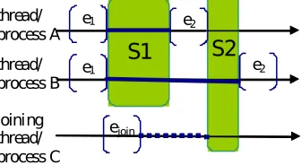
4.1. SCGS in dynamic groups. The described above SCGS detection algorithm assumes a constant number of monitored processes. Each report coming to a synchronizer contains information about an event in a known process. To allow a process to join and leave the monitored (and therefore controlled) group, a synchronizer must be informed about the process group membership changes. We introduce two new message types for that purpose. A join message is used by a new process to tell a synchronizer that it is joining the controlled group, while the leave message terminates the process group membership. The assumption that process clocks are synchronized within a known accuracy must stay true for the joining (and of course the leaving) processes. With this assumption the new messages can be ordered on a time axis using the same rules as standard event messages. As described above, the standard SCGS detection algorithm hops from one event to the nearest one. With dynamic process membership, it is enough to verify if a join or leave message with a timestamp positioned between the current event and the nearest one has been received. A join event should be then processed as follows: increment the number of monitored processN :=N+ 1, rebuild all data structures to reflect this change, set the new process state as reported within the join message. A leave message processing should decrease the number of monitored processesN:=N−1 and all the involved data structures should be rebuilt accordingly, removing the elements corresponding to the process that has left.
Fig. 4.3 shows a situation when the ideal scenario fails. A process join message ejoin from process C
contains a timestamp which should position this event within SCGS S1 and S1 should include three processes. However, the messageejoin arrives with a delay, after S1 has been detected for two processes only. Without
additional assumptions the network delays cannot be anticipated and one should be aware that process joining
P1
P2
e1 e 2
f1 f2
P1
P2
e1 e 2
f1 f2
can be noticed by a synchronizer with a delay.
Fortunately, in environments where the network delays are bounded a better solution is possible. In [21] a SCGS detection algorithm for bounded message transfer times is presented (the UT algorithm). The algorithm postpones processing of the received event reports to make sure that all delayed reports arrive first. The postponing time is computed according the bounded message transfer time. With this algorithm, the detection of S1 in Fig. 4.3 would be postponed until ejoin arrives. Then, Process C would be added to S1 according
to the timestamp value inejoin. The UT algorithm has an obvious drawback — all SCGS detections must be
delayed by the postponing time (proportional to the bound of the message transfer time).
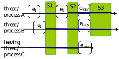
Process leave scenario is shown in Fig. 4.4. The messageeleave arrives just any normal event report with a
timestamp. When S2 is detected, eleave is treated as a normal event report and marks S2 termination. In the
next step,eleave is recognized as a leave message. Information about Process C is deleted from the algorithm
data structures, but prior to thateleave timestamp is copied to the remaining process to mark the beginning of
the next SCGS. The next SCGS S3 contains only processes A and B.
Below, we present the code of an SCGS detection algorithm able to deal with dynamic thread/process membership. The algorithm is an enhanced version of the “T” algorithm from [21] — processing of “join” and “leave” messages has been added. “T” is the simplest SCGS algorithm variant and its presented enhancement permits that the states of joining processes can be taken into account with some delay, as has been explained already. For simplicity, the presented code does not perform data structure compacting — the processes that have left remain as empty entries. This has the advantage that the array indices used as process identifiers are unique (new processes get new indices) and the algorithm presentation is as clear as possible. When necessary, indirect indices can be introduced, i.e. instead if indexi in Pi one should useindi and manage the ind array
appropriately. Such a solution is conceptually straightforward, therefore we will not delve into its technical details.
ALGORITHM 1. SCGC detection using terminated local states Symbols and data structures:
ǫi — quality of clock synchronization, forPi’s clockci and the master clockm:|ci−m|< ǫi Pi — process numberi, i= 1. . . N
e.C — the timestamp attached to evente, a positive number. The value ofǫiis known by the monitor and it
is the monitor task to convert scalar timestamps into intervals: e.C→ he.C−ǫi, e.C+ǫii=he.C1, e.C2i si — currently processed local state of Pi
s.S — event that starts state s
s.T — event that terminates state s Necessary data structures are as follows:
• FIFO queuesQi, i= 1. . . N. Qi holds messages (events) fromPi. Qi.first() is the termination event of
the currently consideredPi state. The following operations are defined on queues, each with the cost
of O(1): Q.first() — the first element in the queue. If the queue is empty, then the method blocks until an element is available; Q.append(s) — puts state s into the queue;Q.remove() — discards the first element;Q.empty() — TRUE iff the queue is empty.
• Array S1...N (Starting) contains events. Si is the starting event of the currently considered Pi state: Si=si.S. The algorithm checks if local statessi:si.S=Si, si.T =Qi.first(),i= 1. . . N, are pairwise
concurrent.
• Priority queuemaxSholds pairshSi.C+ǫi, ii, the first pair component is used as the sort key.
thread/ process A
thread/ process B
e1 e2
e1 e2
joining thread/ process C
ejoin
thread/ process A
thread/ process B
e1 e2
e1
leaving thread/ process C
el eave
ecopy
ecopy
Fig. 4.4: Processing of a process leave message
• Priority queueminT contains recordshQi.f irst().C−ǫi, i, ptri, the first component is used as the key.
A component ptr points to a corresponding record inmaxS(record with the sameicomponent). This queue block themin() operation until the number of entries is equalN−L.
• The following operations are defined on priority queues:
– insert(t,i) : pointer — adds a new record in O(logN), returns a direct pointer to the new element – max() — returns a record with the maximal key in O(1)
– min() — returns a record with the minimal key in O(1)
– max2() — returns a record with the second maximal key in O(1); – min2() — returns a record with the second minimal key in O(1); – removemin() — removes a record with the minimal key in O(logN); – remove(ptr) — removes a record pointed by ptr in O(logN).
• ArraymaxSP tr1...N,maxSP tripoints to record ht, i, ptriin maxS. It is used byminT.insert() to get
a pointer to a corresponding record inmaxS.
• Initially∀i=1...N :Qi.empty() = TRUE;∀i=1...N :Si=e0, wheree0.C= 0;maxS containsh0, i, ptri,
i= 1. . . N;maxSP tri points to recordht, i, ptriin maxS, i= 1. . . N;minT.empty() = TRUE.
The algorithm is as follows:
on reception of the message e(including a leave message) from Pi:
ifQi.empty() then{ Qi.append(e)
minT.insert(e.C−ǫi,i,maxSP tri)
} else
Qi.append(e)
if “monitor was suspended waiting for an event fromPi” then
“resume monitor”
on reception of a join messagej from PN+1:
N =N+ 1
SN =j
maxSP trN =maxS.insert(hj, j.C+ǫi, Ni)
main loop: loop
ht, i, ptri=minT.min() //blocks until minT has N−L elements
min=t
hmax, ji= maxS.max()
ifmin > maxthen{
/* SCGS found, SCGS=hs1, . . . , sNi, wheresi is a local state of Pi
between eventsSi andQi.first() */
if “it is a termination SCGS” then loopexit
}else ifi==j then{
hmin2, i, ptri=minT.min2()
hmax2, ji=maxS.max2()
if (max2< minANDmin2> max) then{
/* SCGS found */
if “it is a termination SCGS” then loopexit
} }
if “Qi.first() is a leave event” then{
L=L+ 1
minT.removemin()
maxS.remove(ptr)
Qi.remove()
} else{
/* search further, the state which terminates first is blocking */
minT.removemin()
maxS.remove(ptr)
maxSP tri=maxS.insert(ht+ 2ǫi, ii) Si=Qi.first()
Qi.remove()
t=Qi.first().C // blocks ifQi is empty minT.insert(ht−ǫi,i,maxSP trii)
}
endloop
5. Process/thread control in PEGASUS. The aim of the PEGASUS framework is to support graphical design of application program execution control governed by global application states. The framework enables a graphical design of the global execution control in distributed programs. In PEGASUS, the program global control design is graphically supported at the program global control flow level and the process/thread level. At both levels graph representation of programs is used.
The program global control flow level is developped using Control Flow Graphical Windows. They enable designing a control flow graph of a distributed program, which shows all control flow dependencies between program blocks, for which the control is governed by application global states. This level enables development of a distributed program in terms of nested high level control constructs acting on program blocks. At the program global control flow level a special kind of the window is additionally used Block Interactions Window, which shows the flow of control data between the blocks specified in graphical representation of the program using control flow graphical windows.
The process and thread level enables designing the structure of internal program code in C/C++ language for terminal program blocks in the control flow graph, i.e. such blocks which will not be further developed to contain nested global high level control constructs. Such terminal blocks correspond to structures of application processes which will be directly assigned to processors. These structures are designed in a special kind of graphical windows which is called Process Structure Window.
The terminal blocks will be converted into source program modules compiled into executable modules after mapping of code blocks to resources using the third graphically supported level of windows which are the Synchronizer Editing Windows and the Thread Block Editing Windows.
GP1(B1, P1,..,Pn; SW)
T F
GP2 (P1,..., Pn; P1,...,Pn)
Synchronizer S
Switch SW1
P1 ... Pn
PAR1
JOIN1
N0 N0
Pn.2 GP3 (P1,..., Pn; P1,...,Pn) Pn.3
Pn.4 Pn.1
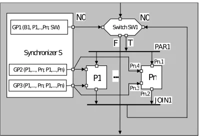
Fig. 5.1: PARALLEL WHILE DO construct with a control flow predicate GP1 and an asynchronous predicate GP2, GP3
blocks, code blocks and switches.
Important elements of the global program control flow graph are synchronizers. The synchronizers are special program blocks which contain control predicate blocks. The synchronizers and the predicates they contain can be assigned to processors or processor cores. A predicate specification includes a predicate name followed by two lists separated by a semicolon: a list of graph blocks (including predicates) whose states are involved in predicate evaluation and a list of signal receiver blocks. We distinguish control flow and asynchronous control predicates. Both can be placed in the same synchronizer. All blocks have communication ports, which are used to draw control data communication paths. Port and port interconnections are automatically drawn by the system if the blocks to connect are specified inside the predicate blocks. However, ports and port connections have to be drawn by a programmer for the control flow which is not specified inside predicates belonging to a program block. In order not to complicate program graph design, the communication concerning computational data is not represented in the program global control flow graphs. The design of the program graph is supported by the replication and nesting facilities. The replication facility enables simplification of the program graph for control constructs, which are acting on the replicated program blocks. The nesting facility enables automatic opening of graphical windows in which nested control constructs can be designed. At block boundary communication ports are automatically generated to enable controlling the interface between the program graph external to the block and the internal graph inside the nested block.
Fig. 5.1 presents an exemplary simple program control flow graph. The graph contains n program blocks Pi governed by a replicated PARALLEL WHILE DO construct. The flow of control is supervised by a global predicate GP3 evaluated on the basis of a global state built of local states of the blocks P1,. . .,Pn. GP1 sends signals to the switch SW1, which directs the flow of control. SW1 asynchronously receives and stores all signals generated by GP1. When the execution control reaches SW1 it directs the flow of control accordingly to the last signal value received.
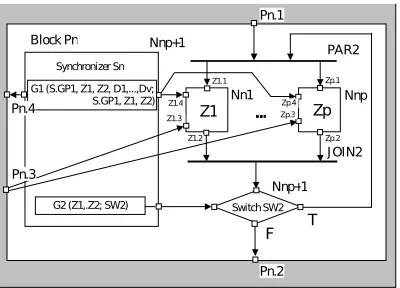
Fig. 5.2 presents the control graph nested inside a block Pn. The replicated program blocks Z1,. . .,Zp are embedded in a PARALLEL DO–UNTIL construct. The flow of control is governed by a global predicate G2 evaluated on the basis of a global state built of local states of Z1,. . .,Zp. Blocks Z1,. . .,Zp are asynchronously controlled by the predicate G1, which is evaluated based on the local states of Z1,. . .,Zp, states of some blocks
D1,. . .,Dv and also signals sent as a result of the predicate GP1 in the synchronizer S. The predicate G1
asyn-chronously controls Z1,. . .,Zp by sending signals to them. Z1,. . .,Zp are additionally directly asynchronously controlled by the predicate GP3 of S.
Before the code of process blocks is designed using the C/C++ language, the process graphs will be first graphically composed of thread blocks and thread level synchronizers in the Process Structure Windows. Fig. 5.3 represents such a window for the replicated Z1,. . .,Zp
blocks from Fig. 5.2. In this window, we can see the thread level synchronizer TS which asynchronously controls thread blocks
Z1
G2 (Z1,.Z2; SW2) Switch SW2
Zp
F T
Synchronizer Sn Nnp+1
Nnp+1 PAR2
J OIN2 Block Pn
Pn.1
Pn.2 Pn.3
Z1.1
Z1.2 Z1.4 Z1.3
Zp.1
Zp.2 Zp.3 Zp.4 G1 (S.GP1, Z1, Z2, D1,...,Dv;
S.GP1, Z1, Z2) Nn1 Nnp
Pn.4 ...
Fig. 5.2: PARALLEL DO–UNTIL construct embedded inside Pn block
Thread
block T1 Synchronizer TS
PAR3
JOIN3 Thread
block T2
TP2 (S.GP2, T1, T2; S.GP2, Sn.G2, T1, T2) Process Zp
Zp.1
Zp.2 Zp.4
Zp.3
TP1 (Sn.G1, T1; Sn.G1, T1)
Fig. 5.3: Process Zp structure in the process and threads graphical window
T2 (R) T1 (R) GP1
S
GP2
GP3
Pn.Sn(R)
G1(R)
G2 (R)
Dv (R)
Pn.SW2(R) Zp.TS(R)
TP1(R)
TP2(R)
Cr(R) SW1
Fig. 5.4: Interactions window of the synchronizer S.
sends states to the predicate G2 of Sn and the predicate GP2 of S.
The PEGASUS framework includes facilities for an easy and convenient representation of the global program execution control. This idea is supported by the Block Interactions Window. It automatically provides a representation of the global control structure in the program related to a selected block of the program control flow graph. This window enables an easy verification of the structure of the global control based on tracing the synchronizers (more exactly their predicates) and thread blocks interactions in the program graph.
S) with other nodes which co–operate with the selected node. The co–operation is implemented by sending or receiving state messages and signals. Inside synchronizer blocks all relevant predicate blocks are shown with the connections to respective synchronizer ports. The window has special facilities to simplify representation of interactions of the replicated blocks. Program blocks which belong to replicated control constructs are displayed only once with notification (R) – replicated, in the names.
6. Process/threads control in dynamic groups. The processes controlled by a synchronizer do not need to know about each other. Therefore they may not be aware of the changing group membership. However, the actions initiated by a synchronizer can be affected by processes leaving/joining the group. A synchronizer upon analyzing a SCGS can decide to send a control signal to a process. If the process decides to leave the group before receiving the signal, the signal will not be delivered. The simplest option is to ignore such signal. If ignoring could cause problems in an application control scheme, the following possibilities, enumerated below, can be exercised.
• A process should confirm signal reception. Not confirmed signals should be “re–processed” e.g. a predicate should be re–evaluated. This solution requires a timeout — the message transfer time must be bounded — otherwise a synchronizer would not know how long to wait for a confirmation.
• A symmetric solution is a negative confirmation — a subsystem responsible for signal delivery can generate an error message for a synchronizer when a target process does not exist. The message transfer time should be bounded as well, if the synchronizer should be able to “re–process” failed signals — it may need to keep some history information for this purpose for a time period dependant on the message transfer time.
• A process should inform the synchronizer that it plans soon to leave the group. Such processes are not eligible as signal targets. This option assumes that a process knows in advance that it will leave the group (not suitable for dealing with process failures) and again the message transfer time must be bounded, so it is known how early a process must send the information about its approaching group leaving.
• Before sending a signal, a synchronizer should ask a target process if it is ready to receive the signal (not suitable for dealing with process failures). This idea induces a large performance penalty, requiring a round trip communication before each signal.
A control scheme can involve actions on more than a single process at a time. As a practical example of such a situation, we can give various load balancing strategies. In the simplest case, a synchronizer selects an over–loaded and an under–loaded process and signals both of them. The process pair should communicate directly and level their load. If one of the selected processes leaves the group after it has been selected and before a peer process contacts it, a communication problem arises. One process from the pair would stall trying to contact a non-existent process. The following solutions, enumerated below, can be taken into account.
• Do not let processes to communicate directly.
• When communicating with a peer process, always use a timeout mechanism — message transfer time must be bounded.
• A process should inform the synchronizer that it plans soon to leave the group. The details are the same as in point c) in the previous subsection.
• Before sending a signal, a synchronizer should ask a target process if it is ready to receive the signal as in point d) in the previous subsection.
A synchronizer must be able to address a proper process/thread to receive a signal. Some difficulties arise here if we want to guarantee that any newly joined process is distinguished from all processes that have left the group. Two situations impose problems in this area.
• Process A is selected as a signal target, but before the signal reaches it, process A leaves the group and process B joins it. If B gets the same identifier as A, it will receive the signal targeted at A.
• If a predicate maintains historical data about process states, and if process A leaves the group and process B joins it, then information about B should not be linked to historical records of A — it means that A and B should have different identifiers.
Local Synchronizer
PAR
J OIN Worker threads
WorkerLoadCheck Node
Z2.1
Z2.2 Z2.4
Z2.3
Best
Load monitor NodeLoadCheck
Thread control
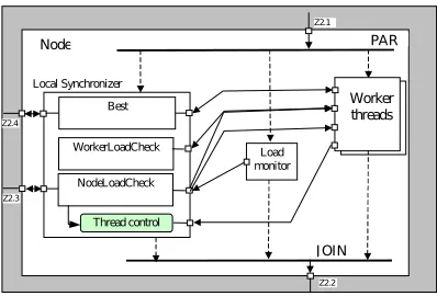
Fig. 7.1: A branch–and–bound search process with dynamic thread creation/deletion
• Each process maintained its local subproblem pool containing partial solutions to be further developed.
• A standard branch–and–bound algorithm was run locally in each process (get a subproblem from a pool, check if it is perspective, branch it, bound each newly created subproblem and return it to the pool).
• The processes reported their load in terms of the estimated size of the subproblems in their pools.
• The synchronizer built global states from those reports to detect load imbalance and dispatched control signals to processes ordering them to communicate and level their loads
• Each new solution better than the currently known best solution was immediately reported to the synchronizer. The synchronizer broadcasted it to all processes using control signals.
PEGASUS let us refine this implementation by introducing thread–level parallelism on each node with a single process running on every node. A local synchronizer on every node can do the same job as the synchronizer for processes in the original solution. To provide the global two–level hierarchical control for all application nodes a global synchronizer which cooperates with the local ones can be introduced [17].
Now, let us assume that the computing system is not used exclusively to solve the branch–and–bound problem. Other tasks can also be run there, possibly with higher priorities. The branch–and–bound application should use all free CPU cores, but should limit itself if other applications are run. Local synchronizers can obtain node load information from a PEGASUS runtime module for CPU load monitoring. It is shown in Fig. 7.1. A single application process (Node) is depicted there. Upon application initialization the local synchronizer, the built–in load monitor and a predefined number of worker threads start executing. The threads report their load and the solutions they find to the synchronizer (to the predicates “WorkerLoadCheck” and “Best”, respectively) and they can receive corresponding control signals (broadcasted new best solution and an order to perform load leveling). They can send the “Join” and “Leave” message to the synchronizer as well. The Thread Control subsystem within the synchronizer handles such messages. Finally, the synchronizer reads the node load from the Load monitor (predicate NodeLoadCheck). This predicate can initiate a thread shutdown by sending control signals to a thread: load balancing aimed to transfer the entire load, and a “Stop” signal telling the thread to report “Leave” and then stop. Additionally NodeLoadCheck can trigger the Thread Control module to start a new thread. Visible external ports Z1.4 and Z1.3 are used to connect local synchronizer to the global one.
When the local load exceeds a given threshold, then the local synchronizer may send control signals to some threads ordering them to shut down. The existing load–balancing mechanism can be used to move the remaining load (subproblem pool contents) from the threads signaled to be cancelled to some others. Normally, a thread is told what portion of its load it should transfer. In this case it should just transfer the entire load. The signaled threads will use the “Leave” message to detach from the synchronizer after the complete load transfer is done. Because the detachment is expected by the synchronizer, the problems described in the previous section are void in this case.
On the other hand, if the load is too low, the synchronizer can create a thread to add more computing power for the branch–and–bound search. The new thread will connect to the synchronizer by the “Join” message. Soon, it will be recognized as an underloaded thread and a standard load balancing action will proceed.
as an overloaded one. Nodes becoming faster due to an increased number of working threads will process their tasks faster and can be recognized as underloaded nodes.
8. Conclusions. The paper has concentrated on new aspects in designing distributed program execution control based on monitoring of application global states. These aspects concern strongly consistent global states monitoring when the number of processes and threads, whose states contribute to the global application control is changing during programs execution. The proposed solutions are oriented towards the PEGASUS distributed program execution framework, which provides a ready to use infrastructure for designing global control in distributed programs governed by predicates evaluated on global application states. An algorithm for detection of strongly consistent global application states has been proposed. It enhances the theoretical background for the PEGASUS framework and contributes to the domain of the design of evolved control for distributed programs.
The PEGASUS framework is currently under implementation based on many–core processors interconnected by separate networks for control and computational data communication, working under the Linux operating system. As the system implements new parallel program control methods, there are no existing libraries which provide the type of high–level services we need. We use standard parallel libraries to implement the basic functionalities like multi threading or message passing. These libraries are used in a standard way. Only some technical details concerning Linux signals and pthreads interaction proved to be non–trivial and we described that topic in [26].
Inter–process control communication is organized by the use of message passing over Infiniband network. Data communication for computations is executed over an Ethernet network. User program code is written in C/C++ language. MPI2 library is used to express data communication in user programs at the process level. OpenMP and pthreads libraries are used to organize user program execution at thread level with inter–thread communication. The code of the PEGASUS execution framework is written C/C++ language supported by the MPI2, OpenMP and pthreads libraries This paper has been partially sponsored by the MNiSW research grant No. NN 516 367 536.
REFERENCES
[1] N. Carriero, D. Gelernter,Linda in Context, in Communications of the ACM 32 (4), April 1989, pp. 444–459 [2] http://www.cs.ucy.ac.cy/courses/EPL441/manifold/tut.pdf, http://reo.project.cwi.nl/
[3] K. Marzullo, D, Wood, Tools for constructing distributed reactive systems, Technical report 14853, Cornell Univer-sity,Department of Computer Science, Feb. 1991,
[4] M. Tudruj,Fine–Grained Global Control Constructs for Parallel Programming Environments, in Parallel Programming and Java: WoTUG–20, IOS, 1997, pp. 229–243.
[5] M. Tudruj, J. Borkowski, D. Kopanski,Graphical Design of Parallel Programs with Control Based on Global Application States Using an Extended P–GRADE System, in Distributed and Parallel Systems, Cluster and GRID Comp., Kluver, Vol. 777, 2004.
[6] M. Tudruj et al.,Distributed Program Control Flow and Behaviour Governed by Global States Monitoring, PARELEC 2011, IEEE CS 2011, pp. 73–78
[7] O. Babaoglu et al.,Group Membership and View Synchrony in Partitionable Asynchronous Distributed Systems: Specifi-cations, in ACM SIGOPS Operating Systems Review, Volume 31 Issue 2, April 1997
[8] A. Bartoli, O. Babaoglu,Application–based dynamic primary views in asynchronous distributed systems, in Journal of Parallel and Distributed Computing Volume 63, Issue 4, April 2003, pp. 410–433
[9] L.E. Moser, P.M. Melliar–Smith, D. A. Agarwal, R.K. Budhia, C.A. Lingley–Papadopoulos, T.P. Archambault,
The Totem System, in Proc. of the 25th Annual International Symposium on Fault–Tolerant Computing, IEEE Computer Society Washington, DC, USA, 1995
[10] N. Lesley, A. Fekete,Providing view synchrony for group communication services, Acta Informatica, vol. 40, Number 3, 159–210, DOI: 10.1007/s00236-003-0129- 4, 2003
[11] J. Pereira, L. Rodrigues, R. Oliveira,Reducing the Cost of Group Communication with Semantic View Synchrony, in Proc.of the International Conference on Dependable Systems and Networks, 2003
[12] P. Brinch-Hansen,The Programming Language Concurrent Pascal, in The Search for Simplicity: Essays in Parallel Pro-gramming, Ch. chapter 7, IEEE Computer Society, pp. 58–79, 1996
[13] A.L. Cox et al.,Software versus Hardware Shared–Memory Implementation: A Case Study, in Proc. Of the 21th Annual International Symposium on Computer Architecture (ISCA’94)
[14] MPI: A Message Passing Interface Standard Ver. 1.1, 1995
[15] M. Tudruj, P. Kacsuk,Extending Grade Towards Explicit Process Synchronization in Parallel Programs, Computers and Artificial Intelligence , Vol.17, 1998, pp. 507–516
[17] J. Borkowski,Parallel Program Control Based on Hierarchically Detected Consistent Global States, PARELEC 2004, Dres-den, Germany, IEEE, pp 328–333.
[18] O. Babaoglu, K. Marzullo, Consistent global states of distributed systems: fundamental concepts and mechanisms, in Distributed Systems (Addison-Wesley, 1995) Consistent global states of distributed systems: Fundamental Concepts and Mechanisms.
[19] Scott D. Stoller,Detecting Global Predicates in Distributed Systems with Clocks, Distributed Computing, Volume 13 Issue 2 (2000) pp. 85–98
[20] F. Cristian, F. Schmuck,Agreeing on processor group membership in timed asynchronous distributed systems, Technical Report CSE95–428, Department of Computer Science, University of California San Diego
[21] J. Borkowski, Measuring and improving quality of parallel application monitoring based on global states, Parallel and Distributed Computing, ISPDC 2005, Lille, France, IEEE.
[22] J. Borkowski, M. Tudruj,Dual Communication Network in Program Control Based on Global Application State Monitoring, ISPDC 2007, July, 2007, Hagenberg, Austria, IEEE CS, pp. 37–44.
[23] J. Borkowski, D. Kopanski, M. Tudruj,Global predicate monitoring applied for control of parallel irregular computations, Euromicro PDP 2007, February 2007, Naples, Italy. IEEE Computer Society 2007, pp. 105–112.
[24] M. Tudruj, J. Borkowski, L. Masko, A. Smyk, D. Kopanski, E. Laskowski,Program Design Environment for Multicore Processor Systems with Program Execution Controlled by Global States Monitoring, ISPDC 2011, IEEE CS, pp. 102–109. [25] J. Borkowski, M. Tudruj, Global Control in Distributed Programs with Dynamic Process Membership, 20th Euromicro
International Conference on Parallel, Distributed and Network–based Processing, 2012, pp.525–529.
[26] J. Borkowski, M. Tudruj, A. Smyk, D. Kopanski,Global Asynchronous Parallel Program Control for Multicore Processors, Lecture Notes in Computer Science, 2012, Volume 7133/2012, pp. 119–130.