Available Online at www.ijpret.com 153
INTERNATIONAL JOURNAL OF PURE AND
APPLIED RESEARCH IN ENGINEERING AND
TECHNOLOGY
A PATH FOR HORIZING YOUR INNOVATIVE WORK
SYNTHESIS OF 128 BIT ADVANCED ENCRYPTION STANDARD ALGORITHM USING
VHDL
MS. KOMAL K. DESAI, PROF. SONIA KUWELKAR
Goa College of Engineering Farmagudi, Goa, India.
Accepted Date: 05/03/2015; Published Date: 01/05/2015
\
Abstract: With the rapid development and wide application of computer and communication networks, the cryptography applied to security in electronic data transactions has acquired an essential relevance during the last few years. The long-serving DES algorithm with 56-bit key length has been broken because of the defect of short keys. The "Rijndael encryption algorithm" invented by Belgian cryptographers Joan Daemen and Vincent Rijmen's had been chosen as the standard AES (Advanced Encryption Standard) algorithm whose packet length is 128 bits and the key length is 128 bits, 192 bits, or 256 bits. . Our main concern AES encryption is based on an iterative round-looping architecture which provides the advantage of low area and power consumption needed by the embedded applications. In this paper all the transformations of Encryption are simulated using an iterative design approach in order to minimize the hardware consumption. This system aims at reduced architecture complexity and high throughput. The design has been coded by Very high speed integrated circuit Hardware Descriptive Language. All the results are synthesized and simulated using Xilinx ISE 10.1 and Model Sim 5.7g software respectively. The system can be implemented using Virtex FPGA.
Keywords: AES, FPGA, VHDL, encryption
Corresponding Author: MS. KOMAL K. DESAI
Access Online On:
www.ijpret.com
How to Cite This Article:
Available Online at www.ijpret.com 154
INTRODUCTION
In recent years symmetric key cryptography has become a high priority and challenging research area .Over the last few years AES encryption has been used in many cryptographic applications. The National Institute of Standards and Technology selected five algorithms in 2000 namely Rijndael, Serpent, Two fish, Mars and RC6 as finalists. Rijndael algorithm was selected as the best algorithm after further analysis since it had the best overall scores in security, performance, efficiency, implementation ability and flexibility. The AES algorithm is a block cipher that can encrypt and decrypt digital information. AES has a fixed block size of 128 bits and the key size can be 128,192 or 256 bits. The hardware implementation of the Rijndael algorithm can provide either high performance or low cost for specific applications.
The AES algorithm is implemented using different which can be categorized as follows. In the first category, pipelining, sub-pipelining and loop unrolling techniques are used to increase operational frequency and throughput .These methods are studied in [1–2]. The second category includes the designs which use lookup table(LUT) for implementation of byte substitution block(S-box). The next category includes several implementations of S-box based on combinational logic circuits in subfields of the composite finite field GF(28). This approach is presented in [1–2]. Efficient implementation of Mix-Columns block is another object which is considered in [2]. Finally, the last category is implementation based on architectures with the number of data path bits lower than 128-bit that are presented in [3–4]. For example, in these designs the data path is 8-bit, 16-bit or 32-bit that is desirable for low-power applications.
An optimized algorithm is presented in [5] where to achieve ultra-high speed and to reduce the latency the algebraic operations are eliminated from the data path. The implementation in[6] using the inner pipeline with two, three, or four stages achieved the throughput 73.737 Gb/s at the maximum frequency of 576.07 MHz. In a paper [7] the use of only one S-box instead of four has made the hardware and area to be reduced, but on the other hand the speed is decreased 4 times. The novelty of this structure is breaking the original 32-bit boundary based AES algorithm into a scalable architecture to work with 8-bit and 16-bit data set for area and power efficient FPGA implementation.
Available Online at www.ijpret.com 155 hardware implementations of encryption algorithms, as they provide physical security, and potentially much higher performance than software solutions. Finally, the implementations of each algorithm compared in an effort to determine the most suitable candidate for hardware implementation within commercially available FPGAs. Serpent algorithm was found to yield the best results when operating in non-feedback mode with throughput 5035.0Mbps, while Rijndael algorithm was found to yield best results when operating in feedback mode with throughput 300.1Mbps [8].
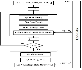
DESCRIPTION OF AES ALGORITHM
In order to better understand the AES structure it is necessary to know the definition of state in the algorithm. State is the matrix of bytes that is processed between many stages, or rounds, and therefore, it will be modified in each stage. In the Rijndael algorithm, the matrix size depends on the block size being used, composed of 4 lines and Nb columns. Here, Nb is the number of bits in the block, divided by 32, since 4 bytes represent 32 bits. Since the AES algorithm uses 128 bit blocks, the state will be composed by 4 lines and 4 columns. The key is grouped by the same fashion as the data block, whereas Nk is the number of columns. Nr is the number of rounds that will be run during the algorithm. The number of runs in the AES will depend on size of the key, where Nr will be 10, 12 and 14, for Nk equals to 4, 6 and 8, respectively. In our design, we consider the case of 128bits for the key length and 10 rounds. Since the block length is 128 bits, i.e.16 bytes, it can be represented by a square array of 4 by 4.The operations in each internal round of AES are performed on this array of bytes called the state. Also, the key is similarly represented as a square array with four rows and four columns. In the following, were call a brief description of the AES algorithm. Each round of AES consists of four different byte- oriented transformations:
1. Byte substitution(S-box).
2. Shifting rows of the state array.
3. Mixing columns of the state array.
4. Key addition to the state array.
Available Online at www.ijpret.com 156 A. Sub-bytes transformation
The Sub Bytes transformation is a non-linear byte substitution, operating on each of the state bytes independently. The SubBytes transformation is done using a once precalculated substitution table called S-box. That S-box table contains 256 numbers (from 0 to 255) and their corresponding resulting values. This approach has the significant advantage of performing the S-box computation in a single clock cycle, thus reducing the latency and avoids complexity of hardware implementation.
B. Shift Row transformation
In Shift Rows transformation, the rows of the state are cyclically left shifted over different offsets. Row 0 is not shifted; row 1 is shifted one byte to the left; row 2 is shifted two bytes to the left and row 3 is shifted three bytes to the left.
B. Mix-Columns transformation
The Mix-Columns transformation is a linear operation on the state which mixes each column of the square array of the state. This transformation has the major diffusion property in the AES algorithm and has a more complex structure than that of Shift-Rows transformation. Each column of the state is considered as a vector with coefficients in GF(28). Then, this vector is multiplied by the 4 by4 constant matrix N over GF(28). The vector–matrix operation is done over the binary field GF(28) with the fixed irreducible polynomial
Available Online at www.ijpret.com 157
Fig 1. Encryption Process
C. Add Round key transformation
The inputs of the Add-Round key transformation are the current 16-byte state and the 16 byte round key which is computed from the Key Expansion algorithm and the output is computed and implemented via a simple bitwise XOR operation. In more details, before the first round, the plaintext is Xored with the main key and, in the round 1–9, the state output of the Mix-Columns transformation is Xored with the round key i.e., the output of the Key-Expansion. But, in the last round, the state output of the Shift-Rows is Xored with the last round key. Notice, the cipher text is the output of the Add-Round key transformation in the last round.
D. AES Key-Expansion algorithm
The AES Key-Expansion algorithm takes the original main key to expand it and generates the round keys. Each round key consists of four 32-bit words which is stored in four 32-bit registers. One round key is generated every round and used during the add round key operation in the encryption process.
I. IMPLEMENTATION AND RESULTS
Available Online at www.ijpret.com 158 using the simulation tools available on Model Sim 5.7g design software. An iterative method of design is implemented to minimize the hardware utilization.
The most expensive one is the Byte substitution, because it is a table lookup operation, implemented as ROM. Each 8 bits requires a 2048 bit ROM. To process 128 bits it is necessary 32768 bits. The Key Expansion uses a Byte substitution operation over 32 bits also, so another 8192 bits should be allocated. Important information is that the code is totally portable, it can be used in any FPGA since it was developed using the standard VHDL. Each module was developed independently from the others, and them they were mounted together.
A. Simulation Results
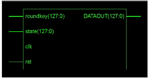
Fig.2. Simulation of 128-bit AES Encryption
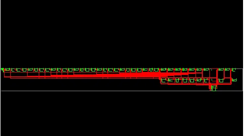
In Fig.2. State is the input 128 bit plain text and the data out is the encrypted cipher text. RST is used to reset module or clear previous data, CLK is used for the synchronization, when the raising edge of CLK is ‘1’ then count is a counter, go on counting from ‘0’ to ‘10’.Fig.3. Shows the RTL schematic of the design and the Fig.4 shows the internal diagram of the RTL schematic in which the iterative approach of the design can be seen.
Available Online at www.ijpret.com 159
Fig. 4. Internal diagram of RTL Schematic
B. Result Analysis
It shows the summary of resources utilized by the basic AEScore for a Virtex 3 device. Out of available 64896 Slice Flip Flops, 64896 4 input LUTs, 804 bonded IOBs and 4 GCLKs and 4GCLKIOBs the designed core has only utilized 906 Slice FlipFlops, 15742 4 input LUTs, , 261 bonded IOBs and 1 GCLKs and1 GCLKIOBs. Thus %age utilization of resources is 1% Slice FlipFlops, 24% 4 input LUTs, 32% bonded IOBs and 25% GCLKs and25% GCLKIOBs.
II. FUTURE SCOPE
Advanced Encryption Standard (AES) is the most secure symmetric encryption technique that has gained worldwide acceptance. Extensive research has been conducted into development of S-box /Inv. S-Box and Mix Columns/Inv. Mix Columns on dedicated ASIC and FPGA to speed up the AES algorithm and to reduce circuit area. A high throughput digital design of the 128 bit Advanced Encryption Standard(AES) algorithm based on the C-slow retiming technique on FPGA can be used.TheC-slow retiming is a well-known optimization and high performance technique.It can enhance designs with feedback loops and automatically rebalances the registers in the design.The C-slow retiming can break the critical path of the design into finer pieces to improve the throughput of the design.The same design can extended to encrypt 192
Logic Utilization Used Available Utilization
Number of Slice Flip flops 906 64,896 1%
Number of 4 input LUTs 15,742 64,896 24%
No. of Slices containing only related logic
8,252 8,252 100%
Available Online at www.ijpret.com 160 and 256 bits of plain text data with proper key length which makes even tougher to decrypt the original data from an unauthorized receivers.
III. CONCLUSION
Hardware for implementing AES algorithm is designed and simulated on Model Sim simulator using VHDL. The design is more efficient and consumes less resources. Our AES encryption is based on an iterative round-looping architecture which provide lowest area. The circuit implementation is very efficient and can be customized to a wide range of applications. The low-cost and low frequency encryption is practically suitable for security focused low resource applications. The popularity of the embedded applications such as smart card, wireless sensor network, RFID technology, etc. has been growing in these recent years.
These embedded applications do not require very fast speed but have a very limited area. Xilinx ISE (integrated software environment) 10.1 tool to be used for simulation and synthesis. The cipher key can be changed with respect to the user requirements. As the S-box is implemented by look-up-table in this design, the chip area and power can still be optimized. Adding data pipelines and some parallel combinational logic in the key scheduler and round calculator can further optimize this design. It represents an improvement over the non-pipeline version and can support many new applications.
REFERENCES
1. Xinmiao Zhang, Keshab K. Parhi, High speed VLSI architectures for the AES algorithm, IEEE Trans. Ver Large Scale Integr.(VLSI) Syst.12(9)(2004) 957–967.
2. T. Good, M. Benaissa, Pipelined AES on FPGA with support for feedback modes (in a multi-channel environment), IET Inf. Secur. 1(1) (2007)1–10.
3. Habibullah Jamaletal. Low power area efficient high data rate16- bit AES crypto processor, in: Proceedings of the 18th IEEE International Conference on Microelectronics (ICM), 2006, pp.186–189.
4. Yi-Cheng Chen, Chung-Cheng Hsieh, Chi-Wu Huang and Chi- Jeng Chang, Kuo- Huang Chang, Embedded a low area 32-bit AES for image encryption/ decryption application, in: Proceedings of the IEEE International Symposium on Circuits and Systems ISCAS,2009,pp.1922–1925.
Available Online at www.ijpret.com 161 6. Mostafa I. Soliman, Ghada Y. Abozaid, FPGA implementation and performance evaluation of a high throughput crypto coprocessor, J. Parallel Distrib. Comput. 71(2011)1075–1084.
7. Namin Yu, Howard M.Heys, Investigation of compact hardware implementation of the advanced encryption standard, in: Proceedings of the IEEE Canadian Conference on Electrical and Computer Engineering, CCECE/CCGEI, Saskatoon, May 2005, pp.1069–1072.
8. Adam J. Elbirt, W. Yip, B. Chetwynd, and C. Paar- “An FPGA Based Performance Evaluation of the AES Block Cipher Candidate Algorithm Finalists” (IEEE 2001).