Available Online at www.ijpret.com 389
INTERNATIONAL JOURNAL OF PURE AND
APPLIED RESEARCH IN ENGINEERING AND
TECHNOLOGY
A PATH FOR HORIZING YOUR INNOVATIVE WORK
SIMULATION AND PERFORMANCE OF TWO PHASE INDUCTION MOTOR
DRIVE USING MATRIX CONVERTER
T. L. BONDE, MR. P. G. SEHWANE, MRS. M. H. SABLEY, P. P. GAIKWAD
Electrical Engineering Department, Faculty of Electrical Engineering, Dr. Babasaheb Ambedkar College Of Engineering & Research Wanadongri, Hingna Road.
Accepted Date: 05/03/2015; Published Date: 01/05/2015
\
Abstract: This paper investigates two phase induction motor drives with using matrix
converter topology. The aim is to reach a set of switches that can produce two phase voltage and current in order to be used in an induction motor. Since it is important to have a desired frequency for motor operation then this task can be achieved using matrix converter Performance of Two Phase induction motor for 50 Hz frequency is batter as compared to one third and three times the fundamental frequency. The proposed strategy can generate the two-phase output voltages/currents where the magnitudes are controlled, and the phase difference is fixed at 90◦. Simulation result for two-phase induction motor produced and presented.
Keywords: Two-phase induction motor, Matrix converter, Switching
Corresponding Author: MR. T. L. BONDE
Access Online On:
www.ijpret.com
How to Cite This Article:
T. L. Bonde, IJPRET, 2015; Volume 3 (9): 389-398
Available Online at www.ijpret.com 390 INTRODUCTION
Two-phase Induction motors have a lot of applications in technology [2].Two-phase induction motors are driven by converter-inverter systems. The converter-inverter circuit, however, requires the smoothing capacitors. The smoothing capacitors are degraded by the environmental temperature and affect the lifetime of the motor drive systems. AC-AC converters has many applications in induction motor drives [1-2]. These converters are becoming popular due to the availability of better switching devices.
Asymmetrical and symmetrical two-phase induction motors fed by single-phase supply have been widely used in small power applications[3-4] .Symmetrical induction motors is a two-phase machine, since its windings are displaced ninety degrees apart from each other. A novel single to two-phase matrix converter (iS2MC) for driving a symmetrical two phase induction motor at 50Hz is proposed in this paper [6]. We show the control algorithm of bidirectional switches in the Two Phase Matrix converter. Simulations prove the effectiveness of the two phase matrix converter system [7-8].
b. II .TWOPHASEINDUCTIONMOTOR
The two phase induction motor category is divided into type 1) Symmetrical Motor 2) Asymmetrical Motor. In this proposed work, the symmetrical two phase induction motor is selected. The symmetrical two phase induction motor has two windings, phase A and phase B, spatially displaced at 90 electrical degrees in the stator. In the symmetrical two phase induction motor, the number of turns of windings of phase A is the same as that of phase B.
c. A. Mathematical Model
Available Online at www.ijpret.com 391 Fig 1. Two-phase induction motor
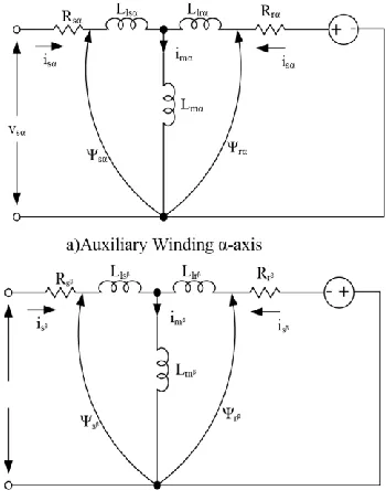
The equivalent circuits representing the symmetrical two-phase induction motor in stationary (αβ) reference frame are shown in Fig.2. The dynamic model equation of symmetrical two phase induction motor can be written in αβ reference frame variables. The stator and rotor voltage of the two-phase induction motor can be expressed as follows:
b)Main Winding in β-axis
Figure 2. Equivalent circuit of an Symmetrical two-phase induction motor in the stationary (αβ) reference frame
sα sα sα sα
sβ sβ sβ sβ d
v =R i + ψ ...(1) dt
d
v =R i + ψ ...(2) dt
Ma i n w i nd i ng
Aux . w i nd i ng
α r - axis
α s - axis
Available Online at www.ijpret.com 392 rα rα rα r rβ
rβ rβ rβ r rα d
v =R + ψ +aw ψ ...(3) dt
d 1
v =R + ψ - w ψ ...(4) dt a
The components of stator and rotor flux linkage equations can also be expressed as:
sα sα sα mα rα
sβ sβ sβ mβ rβ
ψ =L i +L i ...(5) ψ =L i +L i ...(6)
rα mα sα rα rα
rβ mβ sβ rβ rβ
ψ =L i +L i ...(7) ψ =L i +L i ...(8)
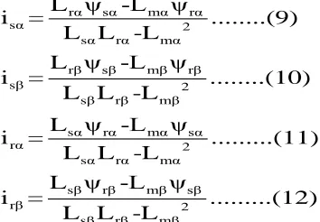
Using equation (5)-(8), as for the stator and rotor current equation are given by:
rα sα mα rα
sα 2
sα rα mα
rβ sβ mβ rβ
sβ 2
sβ rβ mβ
sα rα mα sα
rα 2
sα rα mα
sβ rβ mβ sβ
rβ 2
sβ rβ mβ
L ψ -L ψ
i = ...(9)
L L -L
L ψ -L ψ
i = ...(10)
L L -L
L ψ -L ψ
i = ...(11)
L L -L
L ψ -L ψ
i = ...(12)
L L -L
The equation of electromagnetic torque produced by the machine is then given by the equation:
e p mβ sβ rα mα sα rβ
T =p (L i i -L i i )...(13)
The mechanical dynamic is modelled by the equation:
r e l
d
J w T T ...(14)
dt
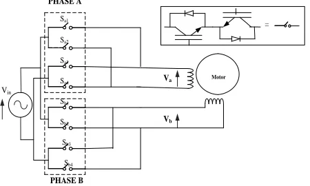
d. III.CIRCUIT CONFIGURATION
Available Online at www.ijpret.com 393
single phase supply is used for driving two phase induction motor. Vin is the supply voltage and Va ,Vb are phase A and phase B voltages respectively.
Sa1
Sb1 Sb2 Sb3
Sb4 Sa2 Sa3 Sa4
=
Va
Vb
Motor
PHASE A
PHASE B
Vin
Fig 3. Configuration of Single Phase to Two Phase Matrix Converter
e. IV.DEVELOPMENT OF CONTROL ALGORITHM
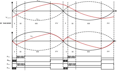
Figure 4 and 5 show the relation of the input and output voltage reference, the actual output and the switching pattern of phase A and phase B respectively.
The voltage Vin ,Vrefa,,V ref b are defined as follows.
Vin=Vi sin (wit)...(1)
Vref a= Vo sin (wot+𝜋
4)...(2)
Vrefb=Vo sin (wot- 𝜋
4)...(3)
The two phase voltages are specified by reference voltage VrefaandVref b. Input voltage frequency and output voltage frequency are defined as wi=2Πfi and wo=2Πfo , respectively. The phase difference of reference to Vin are set to ±𝜋
4 . So that Vref a + V ref b= Vin holds if fo= fi and Vo= 1
√2 Vi
Available Online at www.ijpret.com 394
I III I II III IV
I II IIIIV I II III
Vin
-Vin
Va
IV IV
II
Vref,a
Sa1
Sa2
Sa3
Sa4
Fig 4. Relation between input and output for phase A
I II III IV I II III IV
I II III IV I II III IV Sb1
Sb2
Sb3 Sb4
Vin
-Vin Vref,b
SW MODE
Vb
Fig 5. Relation between input and output for phase B
A. Algorithm to control switches
1] In case |Vref a|<|Vin| (mode II & mode III as shown in fig.2 and3.), Keep Va=Vrefa with buck conversion from Vin or –Vin.
2] In case |Vref a|≥|Vin| (mode I & mode IV in fig.9 and 10) Keep Va=Vin or Va= -Vin .So as to be the same as Vref a.
Available Online at www.ijpret.com 395 TABLE I Switching table for phase A
Mode I II III IV
|Vrefa|*|Vin| + + - -
|Vrefa|-|Vin| + - - +
Sa1 ON PWM OFF OFF
Sa2 OFF OFF PWM ON
Sa3 OFF PWM ON ON
Sa4 ON ON PWM OFF
TABLE II Switching Table for Phase B
Mode I II III IV
|Vrefb|*|Vin| - - + -
|Vrefb|-|Vin| - + + +
Sb1 ON PWM OFF OFF
Sb2 OFF OFF PWM ON
Sb3 OFF PWM ON ON
Sb4 ON ON PWM OFF
B. Simulation of Two Phase Induction Motor with two phase matrix converter
Matlab/Simulink model is developed to examine the performance of symmetrical two-phase induction motor. The equation from (1)-(4) and (9)-(14) have been implemented in Simulink using different blocks. Fig.6shows MATLAB blocks connected for simulating the system. The system is simulated by using system parameter as shown in TABLE III.
TABLE III Parameters of Two Phase Induction Motor
Parameters Rating
StatorResistance (RSα,Rsβ) 4.58Ω
Rotor Resistance (Rrα,Rrβ) 4.93Ω
Stator Inductance (Lsα,Lsβ) 0.2197H
Rotor Inductance (Lrα.Lrβ) 0.2168H
Mutual Inductance(Lmα,Lmβ) 0.2118H
Moment oInertia(J) 2.89Χ10-3Kg-m2
No of Poles 4
A 1
Available Online at www.ijpret.com 396
g. V.SIMULATION RESULT
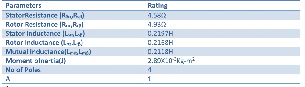
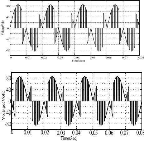
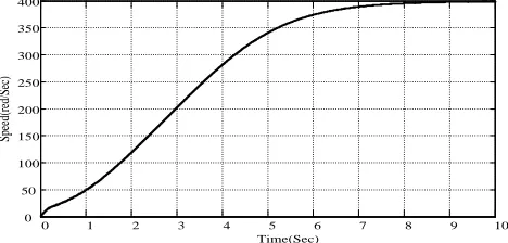
We simulated the matrix converter with ideal switches with two phase induction motor as load. Fig.6.show the two phase voltages simulated for 50Hz. Fig 7 shows the simulated stator currents for various frequencies. Fig.8 shows the speeds of motor for various frequencies.
0 0.01 0.02 0.03 0.04 0.05 0.06 0.07 0.08 -80 -40 0 40 80 Time(Sec) V ol ta ge (V ol t) Time(Sec)
0 0.01 0.02 0.03 0.04 0.05 0.06 0.07 0.08 -80 -40 0 40 80 V o lt a g e (V o lt )
Fig 6. Simulated two phase output voltages when frequency is 50Hz
0 0.01 0.02 0.03 0.04 0.05 0.06 0.07 0.08
-4 -2 0 2 4 6 8 Time(Sec) C ur re nt (A m p)
Iα Iᵝ
Available Online at www.ijpret.com 397
0 1 2 3 4 5 6 7 8 9 10
0 50 100 150 200 250 300 350 400
Time(Sec)
Sp
ee
d(
re
d/
Se
c)
Fig. 8 Speed response of motor for 50Hz.
VI CONCLUSION
A two phase supply is generated from single phase with the help of matrix converter. The matrix converter does not have any energy storage element .Similarly it uses simple algorithm. It also emphasizes the fact that for production of rotating field minimum phases required are two.
Though the performance of motor is not very satisfactory and locus of rotating field is not exactly circular for very simple application which does not require accuracy and exact position control this system can be used .e.g. running a lifesaving gadget in hospital or rural area for a short period such system can be used
XII. REFERENCES
1. Yuji Kudoh, Nobuyuki Otsuka and Kenji Mizutani,“ A Novel Single to Two-Phase Matrix Converter for Driving A Symmetrically Designed Two-Phase Induction Motor,”2013 IEEE,pp 1133-1138,.
2. Jose Rodriguez, Marco RiveraJohan and W. Kolar, “A Review of Control and Modulation Methods for Matrix Converters,” IEEE transactions on industrial electronics, January 2012Vol. 59, No.1pp,58-70.
3. M.Rameshkumar ,Y.Sreenivasa Rao and A.JayaLaxmi, “Modulation and Control techniques of Matrix converter,” International journal of Advance engg,July2012Vol-4,pp.244-255,
Available Online at www.ijpret.com 398
5. M.Asgar, S. Mansourpour, E. Afjei,“Matrix converter for two-phase induction motor application: Analysis, Modeling and simulation”, second power electronics, Drive system and technologies conference,2011,pp-246-250,2011.
6. G. Milan, M. Mohamadian, E. Seifi, and S.M. Dehghan, “A novel minimized switch two-phase matrix converter for driving two-phase induction motor,” PEDSTC 2012., pp. 7-12.
7. P.C.Krause, “Simulation of Symmetrical Induction Machinery,” IEEE transactions on power apparatus and systems, 11 November 1965 Vol. Pas-84, No. 11pp.