doi: 10.11648/j.ijrse.20120101.11
Simple sensorless maximum power extraction control for
a variable speed wind energy conversion system
Mahmoud M. Hussein
1, Tomonobu Senjyu
2, Mohamed Orabi
3, Mohamed A. A. Wahab
4,
Mohamed M. Hamada
41Dept. of Electrical Engineering, Faculty of Energy Engineering, Aswan University, Aswan, Egypt 2Dept. of Electrical Engineering, Faculty of Engineering, Ryukyus University, Okinawa, Japan 3Dept. of Electrical Engineering, Faculty of Engineering, Aswan University, Aswan, Egypt 4Dept. of Electrical Engineering, Faculty of Engineering, Minia University, Minia, Egypt
Email address:
[email protected] (M. M. Hussein), [email protected] (T. Senjyu), [email protected] (M. Orabi), [email protected] (M. A. A. Wahab), [email protected] (M. M. Hamada)
To cite this article:
Mahmoud M. Hussein, Tomonobu Senjyu, Mohamed Orabi, Mohamed A. A. Wahab, Mohamed M. Hamada. Simple Sensorless Maximum Power Extraction Control for a Variable Speed Wind Energy Conversion System. International Journal of Renewable and Sustainable
Energy. Vol. 1, No. 1, 2012, pp. 1-10. doi: 10.11648/j.ijrse.20120101.11
Abstract:
This paper proposes a simple sensorless maximum power extraction control strategy for a variable speed wind energy conversion system (VSWECS) based on permanent magnet synchronous generator (PMSG). The PMSG is connected to the grid through a switch mode rectifier and a three phase voltage source inverter (VSI). Control of the generator side converter is used to achieve maximum power from the available wind power. This by Simple estimating of PMSG generator speed and using the estimated generator speed to calculate mechanical power generated from wind power. So, the optimum power coefficient of the wind turbine can be achieved from the governed relation between the generator speed and mechanical power. The grid side voltage source inverter uses a hysteresis current controller to supply power at unity power factor into the grid. Extensive simulations have been performed using MATALB/SIMULINK. Simulation results demonstrate that the controller can extract maximum power from available wind power and achieve unity power factor at the grid with different wind speeds.Keywords:
Permanent Magnet Synchronous Generator; Maximum Power Extraction; Variable Speed Wind Energy System; Switch Mode Rectifier; Hysteresis Current Controller1. Introduction
Nowadays, wind energy has become the fastest growing power sector in the world and becomes more widely adopted in the future because it is clean energy source and it is one from the infinite natural resources. Also, it is one of the available non-conventional energy sources. Variable speed wind energy systems have many advantages over than fixed speed wind energy systems such as yielding maximum power output while developing low amount of mechanical stress, improved efficiency, and power quality [1]. Presence of power electronic devices with variable speed system is very important, where AC-DC converter is used to convert AC voltage with variable amplitude and frequency from generator to DC voltage. The DC voltage is converted again to AC voltage with fixed amplitude and frequency at the grid for electrical utilization [2,3]. Among the various grid
connected types of wind turbines, the directly driven permanent magnet synchronous generator (PMSG) has obtained rising attention due to several advantages such as it has simple structure, ability of operation at low speed, self excitation capability, leading to high power factor and high efficiency operation. In the case PMSG operating at low speed there is no need to use a gearbox to match the turbine and rotor speed which suffers many times from faults and requires regular maintenance, which makes the system unreliable [4,5].
There are two common types of interfaces between PMSG and the grid. The first configuration is designed as back-to-back PWM converters [11-13], the second configuration is a single switch mode rectifier and an inverter [14-16]; the former one is commonly considered as the technical ultimate operation but may be more expensive and complex, it has a lot of switches which cause more losses and voltage stress in addition to the presence of Electromagnetic Interface (EMI). The later one, which adopted in this paper, is usually used in the stand-alone or small scale wind farms for its simple topology and control, and most importantly, low cost.
Most recent papers try to achieve maximum power from wind turbine without using mechanical sensors which measure the value of wind speed and or the value of PMSG rotor speed, using these sensors lead to inaccurate measurements due to mechanical parts consideration. So,
sensorless extraction of maximum power should be achieved by another technique other than measuring wind and or rotor speed of PMSG.
Hence this paper proposes a simple strategy to achieve maximum power extraction from the available wind turbine power. This can be done by estimating generator speed of PMSG from measuring the average DC voltage and current of the uncontrolled rectifier; optimum mechanical power from wind turbine can be easily calculated from estimated generator speed; using a hysteresis current control to adjust the duty cycle of the DC-DC boost converter switch. Moreover, in order to achieve unity power factor at the grid, a hysteresis current controller is applied to control the injected reactive power to the grid to be zero.
2. Wind Energy Conversion System
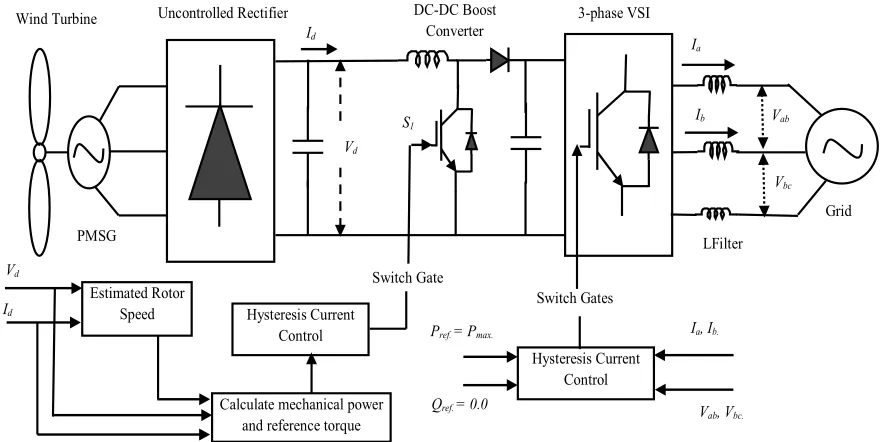
Figure 1. Power Circuit topology combined with control structure.
Fig.1 shows that the power circuit topology and control structure of the proposed variable speed wind turbine that proposed in this paper. The system consists of the following:
Wind turbine.
Permanent magnet synchronous generator (PMSG), which is directly driven by the wind turbine without using a gearbox.
A single switch three phase mode rectifier, which consists of a three phase diode bridge rectifier and DC-DC boost converter, uses a simple sensorless control to achieve maximum power from available wind power.
A three phase VSI which is connected to the grid through a passive L filter. It uses a hysteresis current controller to achieve unity power factor at the grid. The phase voltage and its frequency at the grid are 220V and 50Hz, respectively.
Table 1 [17] shows the parameters of wind turbine and PMSG which are used in this paper. The proposed model has been modeled and simulated using MATLAB/SIMULINLK software program.
Table 1. Parameters of wind turbine and generator system.
Wind turbine
ρ Air density 1.1 kg/m3
R Radius of blade 4.4 m
Cp Optimum power coefficient 0.48
ʋw Based wind speed 12 m/sec.
Permanent magnet synchronous generator (PMSG)
Pr Rated output power 20 kW
Nr Rated mechanical speed 211 rpm
Pole ( p) Number of poles 36
ENL Peak line –to-neutral back emf in no-load 295.6 V
Rs Stator winding resistance 0.1764 Ω
Ls Stator leakage inductance 4.48 mH
Km Peak line-to- neutral back emf constant 1.4 V/rpm Wind Turbine
Estimated Rotor Speed PMSG
Uncontrolled Rectifier DC-DC Boost
Converter 3-phase VSI
Grid
Calculate mechanical power and reference torque
Hysteresis Current Control Switch Gates Hysteresis Current
Control
Switch Gate
S1
Id
Vd
Vd
Id
Pref. = Pmax.
Qref. = 0.0
Ia
Ib
Ia, Ib.
Vab, Vbc.
Vab
Vbc
3. Generator Side Converter Control
The mechanical power captured from wind turbine is governed by the following equation:
3 0.5
m p w
P = ρAC υ (1)
Where Pm is the mechanical output power (Watt), ρ is the
Air density (Kg/m3), A is the swept area (m2), C
p is the
power coefficient of the wind turbine and ʋw is the wind
speed (m/sec.). Consequently, the output energy is determined by the power coefficient (Cp) if the swept area,
air density, and wind speed are assumed to be constant. Cp is
function in tip speed ratio (λ) and pitch angle (β) in degree. If β is equal zero, in this case Cp is only function in λ as shown
in (2), and λ is function of rotor mechanical speed, rotor
radius of blade and wind speed as indicated in (3).
( )
(
)
21 0.735
60.04 4.69 0.0068
1 0.035
p e
C
λ λ
λ λ λ
λ λ
− +
= − +
− (2)
r
w
ω R λ
υ
= (3)
Where ωris the rotational speed (rad/sec.) and R is the
radius of blade (m). The relation between Cp and λ when β
equal zero degree is shown in Fig. 2. It can be noticed that the optimum value of Cp is about 0.48 for λ equal 8.1.
Maximum power extraction from wind turbine can be achieved when the turbine operate at optimum Cp (Cp-opt).
Therefore, it is necessary to adjust the rotor speed at optimum λ (λopt) with wind speed variation.
Figure 2. The relation between power coefficient (Cp) and tip speed ratio
(λ).
Using (1) and (3), the output optimum power from wind turbine can by written as:
(
)
_ _ _ _ 3 0.5 3 r opt m opt p optr opt opt R P AC opt K ω ρ λ ω = =
(4)Where:
_
3 0.5
opt p opt opt
R
K
ρ
ACλ
=
(5)_
opt
r opt R w Kω w
λ
ω
=υ
=υ
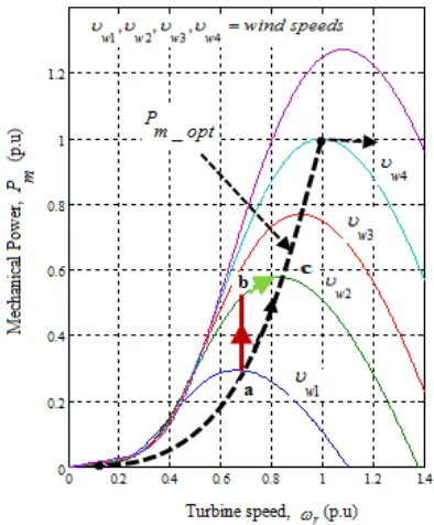
(6)Fig. 3 indicates that the mechanical powers generated by the turbine as a function of rotor speeds for different wind speeds. The maximum power extraction within the allowable range can be achieved if the controller can properly follow the optimum curve with variation of wind speed.
Figure 3. The relation among generated mechanical powrs and rotr speeds for different wind speeds.
The generator side converter (a single switch three phase mode rectifier) is controlled to extract maximum power from the available wind turbinepower. Hence, the wind turbine can produce maximum power when the turbine operates at Cp-opt. So it is necessary to adjust the rotor speed
at λopt.
The structure of the proposed control strategy of the switch mode rectifier is shown in Fig. 4. The controller objective is control the duty cycle of the DC-DC boost converter switch S1 which is shown in Fig.1 to extract
maximum power from the available wind turbine power.
0 1 2 3 4 5 6 7 8 9 10 11 12 13 14
0 0.05 0.1 0.15 0.2 0.25 0.3 0.35 0.4 0.45 0.5
Tip Speed Ratio
Figure 4. The generator side converter control strategy.
The control algorithm includes the following steps: Estimate generator speed, ωg Generator speed of PMSG
can be estimated by measuring the average output voltage Vd
and current Id of the uncontrolled bridge rectifier and by
knowing the parameters of PMSG used in this paper which are given in Table 1.
The relation among generator speed, PMSG parameters,
Vd andId is governed by (7).
(
)
(
23 3 2)
60
2
d s d g
m s d
V R I
p
K L I
π ω
π
+ =
− (7)
Where ωgis the generator speed in (rad/sec.). Fig. 5 gives
a configuration of (7) in MATLAB/SIMULINK. The generator speed (ωg) equal rotational speed (ωr) where there
is no gearbox between wind turbine and PMSG.
Figure 5. Estimating of permanent magnet synchronous generator speed, ωg (rad/sec.).
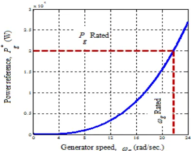
Determine the reference power as shown in Fig. 6, which describes the relation between the generator reference power and the generator speed, using (8).
( )
* g 3
g opt
P = K ω (8)
Figure 6. Generator power reference versus generator speed.
This reference power is then used to calculate the reference DC current as indicted in (9).
*
* g
dc dc
P I
V
= (9)
The error between the reference and measured DC current is used to adjust the duty cycle of the DC-DC boost converter to operate the generator speed at optimum speed through a hysteresis current controller to extract maximum power. The hysteresis band of the hysteresis current controller is 0.2 A.
To describe the control function, considering Fig. 3. If the PMSG operating at point ‘a’ and wind speed increases from
ʋw1 to ʋw2(point ‘b’), the additional power causes the PMSG
to accelerate also causes difference between reference DC current and measured DC current, this difference operate to adjust the duty cycle of DC-DC boost converter to achieve optimum speed of the PMSG ωg which attain maximum
power extraction. Finally, the generator will reach the point ‘c’ where the difference between the reference and measured DC current is within the bandwidth of the hysteresis current controller. A similar situation occurs when the wind speed decreases.
In this proposed strategy, no need to measure wind and generator speed using mechanical sensors.
4. Grid Side Converter Control
The grid side converter, a three phase VSI, is used as an interface between the single switch mode rectifier and the grid. The grid connected to the VSI via a passive L filter for AC smoothing.
In this paper, the specified grid phase voltage and its frequency are 220V and 50Hz, respectively. To achieve unity power factor at the grid, the voltages Vab and Vbc
should be measured and transformed from stationary abc
reference frame to rotating dq reference frame using the
chosen electrical grid voltage frequency.
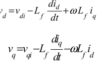
The voltage equations using dq transformation in the
rotating reference frame are:
Estimating generator
speed
Power reference calculation
Hysteresis current controller
To switch S1 in Fig 1
÷
*
+ _ Id
Vd
ωg Pg*
d
d di f f q
di
v v L L i
dt
ω
= − + (10)
q q qi f f d
di
v v
L
L i
dt
ω
= −
−
(11)So, the active and reactive powers by using the dq
transformation are given by:
(
)
3
2
d d q qP
=
v i
+
v i
(12)(
)
3
2
d q q dQ
=
v i
+
v i
(13)If the reference frame is as vq = 0 and vd = │V│, the
equations for active and reactive power will be,
(
)
3 3
2 d d 2 d
P= v i = V i (14)
( )
3 3
2 d q 2 q
Q= v i = V i (15)
From (14), Id
* can be calculated where the reference
active power is the maximum power extracted from the wind turbine. In order to achieve unity power factor, the reference reactive power Q should be equal zero. So in (15), Iq
*should
be equal zero. Reference currents in stationary abc reference
frame can be easily getting by transforming the rotating dq
reference current. A simple hysteresis current controller is employed to achieve unity power factor at the grid. Where the hysteresis band of the hysteresis current controller is 0.8 A. Fig. 7 shows the control strategy of the grid side VSI to achieve unity power factor at the grid.
Figure 7. Control strategy of the grid side voltage source inverter.
5. Simulation Results
The proposed control strategy for the variable speed wind energy conversion system to extract sensorless maximum power from wind turbine power and achieve unity power factor at the grid is simulated using MATLAB/SIMULINK software program. Fig. 8 shows the simulation block diagram for the system.
Figure 8. Power Circuit topology combined with control structure.
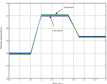
Fig. 9 shows the wind speed that incident on the wind turbine, where the wind speed steps up at time 1.5 second from 8.5 m/sec. to 12 m/sec. during 0.5 second time span and at time 3.25 second it steps down from 12 m/sec. to 10 m/sec. also during 0.5 second time span. The estimated and
calculated generator speed are indicated in Fig. 10, where it varies with changing the wind speed to obtain optimum power coefficient Cp and consequently extract maximum
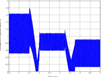
power from wind turbine. The percentage error between the calculated and the estimated generator speed is found less
sin_cos
Discrete,
Ts = 2e-006 s. abc
sin_cos dq0 Tm Wind Turbine v + -v + -v + -Ia,Ib Vdq sin-cos Pmax. Inv erter Siwtch gates
Unity power factor control
A B
C
The Grid
Maximum power Extracted Wind speed A B C + -Rectifier Bridge Tm m A B C PMSG
I n M ean
Mean Value (linear) Id Vd MPPT Controller L1 L filter g C E IGBT/Diode g A B C + -IGBT Inverter [Vd] [Id] [EstimatedWr] [switchgates] [Vd] [Id] [EstimatedWr] [switchgates] Id Vd
Estimated Wg (rad/sec.)
-than 2% as shown in Fig. 11. Fig. 12 shows the value of power coefficient Cp, it is clear that the simple control
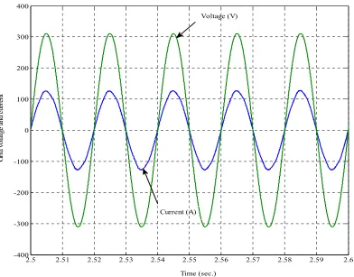
technique works very well where the value of power coefficient is kept at its optimum value which equal 0.48 with varying in the wind speed to obtain maximum power. Figs. 13, 14, and 15 indicate that the instantaneous output phase voltage and current (phase current multiplied by 3 to indicate the phase relation between it and voltage) of a phase
(phase A) from output three phase when the wind speed transfers from 8.5 m/sec. to 12 m/sec., 12 m/sec., and 10 m/sec., respectively. Which clear that the unity power factor at the grid has been achieved with different wind speeds. The average output power according to the wind speed is shown in Fig. 16, whereas this value of the power is the maximum extracted power from the available wind power because the value of power coefficient Cp is at optimum value.
Figure 9. Wind speed incident on the wind turbine (m/sec.).
Figure 10. Estimated and calculated generator speed (rad/sec.).
0.5 1 1.5 2 2.5 3 3.5 4 4.5 5
6 7 8 9 10 11 12 13 14
Time (sec.)
W
in
d
sp
ee
d
(m
/s
ec
.)
0.5 1 1.5 2 2.5 3 3.5 4 4.5 5
12 14 16 18 20 22 24
Time (sec.)
G
en
er
at
or
s
pe
ed
(r
ad
/s
ec
.)
Calculated
Figure 11. Percentage error of the generator speed (%).
Figure 12. Power coefficient of wind turbine (Cp).
0.5 1 1.5 2 2.5 3 3.5 4 4.5 5
0 0.2 0.4 0.6 0.8 1 1.2 1.4 1.6 1.8 2
Time (sec.)
Pe
rc
en
ta
ge
e
rr
or
o
f g
en
er
at
or
s
pe
ed
(%
)
0.5 1 1.5 2 2.5 3 3.5 4 4.5 5
0.34 0.36 0.38 0.4 0.42 0.44 0.46 0.48 0.5
Time (sec.)
Pw
er
C
oe
ff
ic
ie
nt
(C
Figure 13. Grid voltage and current with increasing wind speed from 8.5 m/sec. to 12 m/sec.
Figure 14. Grid voltage and current when the wind speed is 12 m/sec.
1.7 1.71 1.72 1.73 1.74 1.75 1.76 1.77 1.78 1.79 1.8
-400 -300 -200 -100 0 100 200 300 400
Time (sec.)
G
ri
d
vo
la
tg
e
an
d
cu
rr
en
t
Voltage (V)
Current (A)
2.5 2.51 2.52 2.53 2.54 2.55 2.56 2.57 2.58 2.59 2.6 -400
-300 -200 -100 0 100 200 300 400
Time (sec.)
G
ri
d
vo
la
tg
e
an
d
cu
rr
en
t
Voltage (V)
Figure 15. Grid voltage and current when the wind speed is 10 m/sec.
Figure 16. Maximum output power from the available wind power.
6. Conclusions
Control strategy for a variable speed wind energy conversion system has been presented in this paper along
with a comprehensive analysis and simulation using MATLAB/SIMULINK. From the simulation results, the maximum power extraction control algorithm at the generator side converter has been implemented based on estimating generator speed, using the relation curve between
4.5 4.51 4.52 4.53 4.54 4.55 4.56 4.57 4.58 4.59 4.6
-400 -300 -200 -100 0 100 200 300 400
Time (sec.)
G
ri
d
vo
la
tg
e
an
d
cu
rr
en
t
Voltage (V)
Current (A)
0.5 1 1.5 2 2.5 3 3.5 4 4.5 5
0.6 0.8 1 1.2 1.4 1.6 1.8 2 2.2x 10
4
Time (sec.)
O
ut
pu
t p
ow
er
(W
generator speed and mechanical power to adjust the generator speed operation at optimum value through a hysteresis current control for extracting maximum power from the available wind power. Additionally, a simple hysteresis current controller has been employed on the grid side VSI to get unity power factor at the grid. Simulation results proved that the proposed control scheme has a great capability to obtain unity power factor at the grid side and to achieve sensorless maximum power from the available wind power.
References
[1] S. Muller, M. Deicke and R. W. De Doncker, “Doubly fed induction generator systemfor wind turbines,” IEEE Ind. Appl. Magn, vol. 8, no. 3, pp. 26-33, May 2002.
[2] T. Ackerman and L. Soder, “An overview of wind energy status 2002,” Renew. & Sus. Energy Reviews, pp. 67-128, June 2002.
[3] J. A. M. Bleij, A. W. K. Chung and J. A. Rudell, “Power Smoothing and Performance Improvement of Wind Turbines with Variable Speed,” Proc. of 17th British Wind Energy Assoc. Conf., Warwick, pp. 353-358, July 1995.
[4] A. J. G. Westlake, J. R. Bumby and E. Spooner, “Damping the power-angle oscillations of a permanent magnet synchronous generator with particular reference to wind turbine applications,” IEE Proceedings, Elec. Power Appl., Vol 143, No 3, pp. 269 – 280, May 1996.
[5] A. J. G. Westlake, J. R. Bumby and E. Spooner, “Damping the power-angle oscillations of a permanent magnet synchronous generator with particular reference to wind turbine applications,” IEE Proceedings, Elec. Power Appl., Vol 143, No 3, pp. 269 – 280, May 1996.
[6] T. Senjyu, S. Tamaki, E. Muhando, N. Urasaki, H. Kinjo, T. Funabashi, H. Fujita and H. Sekine, “Wind velocity and rotor position sensorless maximum power point tracking control for wind generation system,” Renew. Energy, Vol. 31, pp. 1764-1775, Sep. 2006.
[7] T. Pan, Zh. Ji and Zh. Jiang, “Maximum Power Point Tracking of Wind Energy Conversion Systems Based on Sliding Mode Extremum Seeking Control,” Energy 2030, IEEE Conf., pp. 1 – 5, Nov. 2008.
[8] J. Hui and A. Bakhshai, “A new adaptive control algorithm for maximum power point tracking for wind energy conversion systems,” Power Electronics Specialists, PESC, IEEE Conf., pp. 4003 – 4007, June 2008.
[9] L. Fan, Zh. Miao and X. Wang, “Sensorless Maximum Power Point Tracking in multi-type wind energy conversion systems,” Decision and Control, 28th Chinese Control, 48th IEEE Conf., pp. 6823 – 6828, Dec. 2009.
[10] M. E. Haque, M. Negnevitsky and K. M. Muttaqui, “A Novel Control Strategy for a Variable-Speed Wind Turbine with a Permanent –Magnet Synchronous Generator,” IEEE Trans. on Ind. Appl., vol.46, no. 1, pp. 331-339, Jan./Feb. 2010. [11] M. Chinchilla, S. Arnaltes and J. C. Burgos, “Control of
Permanent-Magnet Generators Applied to Variable-Speed Wind-Energy Systems Connected to the Grid,” IEEE Trans. Energy Conversion, vol. 21, pp.130-135, Mar.2006. [12] D. Luo, Y. Sun, Sh. Huang and K. Huang, “Control of
Direct-Drive Permanent-Magnet Wind Power System Connected to Grid,” Electrical Machines and Systems, ICEMS, IEEE International Conf., pp. 2459 – 2463, Oct. 2008.
[13] J. S. Thongam, H. Ezzaidi and M. Ouhrouche, “Wind Speed Sensorless Maximum Power Point Tracking Control of Variable Speed Wind Energy Conversion Systems,” Electrical Machines and Drives, IEMDC, IEEE International Conf., pp. 1832-1837, May 2009.
[14] K. Tan and S. Islam, “Optimum control strategies in energy conversion of PMSG wind turbine system without mechanical Sensors,” IEEE Trans. Energy Conversion, vol.19, pp.392-399, June 2004.
[15] M. Malinowski, W. Kolomyjski, M. P. Kazmierkowski and S. Stynski, “Control of variable-speed type wind turbines using direct power control space vector modulated 3-level PWM converter,” Industrial Technology, IEEE International Conf., pp. 1516-1521, Dec.2006.
[16] A. Rolan, A. Luna, G. Vazquez, D. Aguilar and G. Azevedo, “Modeling of a variable speed wind turbine with permanent magnet synchronous generator,” Ind. Electronics, ISIE, IEEE International Symposium , pp. 734-739, July 2009.